U.S. Department of Transportation
Federal Highway Administration
1200 New Jersey Avenue, SE
Washington, DC 20590
202-366-4000
Federal Highway Administration Research and Technology
Coordinating, Developing, and Delivering Highway Transportation Innovations
 |
| This report is an archived publication and may contain dated technical, contact, and link information |
|
Publication Number: FHWA-HRT-06-139
Date: October 2006 |
|
The period-shift electronics unit utilizes the change in inductance caused by a vehicle passing over a loop to measure the altered electronics unit oscillator frequency using a counter to count the number of pulses that occur during the electronics unit oscillator period. |
Appendix H describes the derivation of the digital period-shift electronics unit sensitivity, which is shown to be proportional to the threshold count Npt divided by the total number of counts Npc in the frequency counter. The response time is proportional to the threshold count, divided by the product of the sensitivity and the frequency of the crystal clock.
The oscillator in a digital period-shift electronics unit operates at a frequency fD, which is determined by the loop, lead-in cable, and the electronics unit tuning network. The number m of oscillator cycles from the period scaler determines the length of the gating pulse applied to the AND gate. When the gating pulse is m times as long as the loop is occupied, more clock pulses are sent to the period counter, making the electronics unit more sensitive.
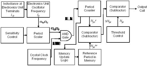
A simplified block diagram of a single channel, digital period-shift vehicle electronics unit is illustrated in Figure H-1. The change in inductance at the electronics unit terminals caused by a vehicle produces a change in the oscillator frequency. The sine wave oscillator frequency is converted by a period scaler into a square wave. The square wave is input to an AND gate, which compares the signal level (i.e., high or low) to that of the crystal clock frequency pulse.

Figure H-1. Digital period-shift electronics unit block diagram.
If both the square wave and the crystal clock pulse are high, a count is sent to the period counter. The count is equal to the number of clock pulses that occur in a period.
At the end of the period, the count is sent to the first comparator. The comparator subtracts the reference period count stored in memory, which represents the count when no vehicle is present, from the current period count. The difference enters the second comparator. If the second comparator finds that the difference is in excess of the threshold sensitivity, then a vehicle is presumed present and a call is output.
The period TDC of the electronics unit oscillator is
| (H-1) |
| where | ||
| TD | = 1/fD = period of electronics unit oscillator in s | |
| fD | electronics unit oscillator frequency in Hz | |
| m | number of oscillator cycles from the period scaler. |
The length of the gating pulse is
 |
(H-2) |
The number Npc of clock pulses counted by the period counter is
|
The count of the period counter is proportional to the electronics unit oscillator period TD |
 |
(H-3) |
where TC is the period of the crystal clock equal to the inverse of the clock frequency.
The number of clock pulses stored in the reference memory when no vehicle is present is
 |
(H-4) |
The number of clock pulses counted when a vehicle is present is
 |
(H-5) |
Since the loop inductance decreases when a vehicle is sensed, the electronics unit oscillator frequency fD increases and the oscillator period TD decreases. Then
| (H-6) |
The output of the first comparator is
 |
(H-7) |
Since
 |
(H-8) |
the output of the first comparator can be written as
 |
(H-9) |
|
The output count of the first comparator is proportional to the change ΔTD in the oscillator period. |
When the output count ΔNpc of the first comparator equals the threshold count Npt in the second comparator, a vehicle call results.
Then,
| (H-10) |
Thus,
 |
(H-11) |
For a high quality factor tuned circuit, the normalized period shift is approximated by
 |
(H-12) |
Solving for sensitivity, we get
 |
(H-13) |
 |
(H-14) |
Since
 |
(H-15) |
and
 |
(H-16) |
 |
(H-17) |
when
 |
(H-18) |
 |
(H-19) |
Letting
 |
(H-20) |
the sensitivity becomes
 |
(H-21) |
since
 |
(H-22) |
from Equation H-3,
 |
(H-23) |
The sensitivity of the digital period-shift electronics unit is twice the threshold count divided by the maximum number of counts on the period counter. |
The response time of the digital period-shift electronics unit is primarily due to the time required to fill the period counter with clock pulses. Thus,
 |
(H-24) |
Rewriting equation H-23 to solve for Npc, we get
 |
(H-25) |
Upon substituting this result into equation H-24, the response time becomes
 |
(H-26) |
Previous | Table of Contents | Next
FHWA-HRT-06-139 |