U.S. Department of Transportation
Federal Highway Administration
1200 New Jersey Avenue, SE
Washington, DC 20590
202-366-4000
Federal Highway Administration Research and Technology
Coordinating, Developing, and Delivering Highway Transportation Innovations
 |
| This report is an archived publication and may contain dated technical, contact, and link information |
|
Publication Number: FHWA-HRT-04-091
Date: August 2004 |
|||||||||||||||||||||||||||||||||||||||||||||||||||||||||||||||||||||||||||||||||||||||||||||||||||||||||||||||||||||||||||||||||||||||||||||||||||||||||||||||||||||||||||||||||||||||||||||||||||||||||||||||||||||||||||||||||||||||||||||||||||||||||||||||||||||||||||||||||||||||||||||||||||||||||||||||||||||||||||||||||||||||||||||||||||||||||||||||||||||||||||||||||||||||
Signalized Intersections: Informational GuidePDF Version (10.84 MB)
PDF files can be viewed with the Acrobat® Reader® CHAPTER 11 — APPROACH TREATMENTSTABLE OF CONTENTS 11.1 Signal Head Placement and Visibility 11.1.1 Convert to Mast arm or Span Wire Mounted Signal Heads 11.1.2 Add Near-Side signal Heads 11.1.3 Increase size of Signal Heads 11.1.4 Use two Red Signal Sections 11.1.5 Increase Number of Signal Heads 11.1.7 Provide Advance Warning 11.2 Signing and Speed Control Treatments 11.3 Roadway Surface improvements 11.3.1 Improve Pavement Surface 11.3.4 Remove Obstacles from Clear Zone 11.4 Sight Distance treatments
LIST OF FIGURES
LIST OF TABLES 11. Approach TreatmentsApproaches are critical components of a signalized intersection. It should be obvious to someone approaching by motor vehicle, bicycle, or on foot that an intersection is ahead, and the traffic control device is a traffic signal. Adequate signing and pavement marking is required to provide the driver with sufficient information to determine the appropriate lane to choose and direction to travel. The pavement on the approaches should provide the driver with a smooth, skid-resistant surface, with adequate drainage. The approaches ideally should meet at right angles and should be at grade and free of unnecessary clutter and obstacles. Sight distance for all approaches should be adequate for drivers proceeding through the intersection, particularly those making a left turn. This chapter will discuss various treatments related to signalized intersection approaches, as summarized in table 92. Table 92. Summary of approach treatments.
11.1 Signal Head Placement and VisibilityTraffic signals should be placed so the signal heads are visible at a distance upstream of the intersection and from all lanes on the approach. Approaches with poorly placed traffic signals are likely to experience an increase of rear-end conflicts and collisions. At intersections with a higher proportion of heavy trucks, drivers in adjacent lanes or following a heavy vehicle may not be able to see the signal indication, which may lead to inadvertent red light running. Many red light runners claim they did not see the traffic signal, and often the reason is the poor placement of traffic signal heads or a failure to make the traffic signal head visually prominent. Approach treatments that improve signal visibility will aid drivers in making decisions at the intersection and forewarn them of a signalized intersection. Subsequently, the probability of driver error, such as inadvertently running a red light and being involved in a collision, is lower. The following sections identify traffic control treatments that can be applied to improve the visibility of signal heads. 11.1.1 Convert to Mast arm or Span Wire Mounted Signal HeadsDescriptionThree major types of signal head placement are in popular use today: pedestal, span wire, or mast arm mounted. Merits and drawbacks of each were discussed in chapter 4. For a signalized intersection experiencing safety problems related to the placement or visibility of a pedestal-mounted signal head, the traffic engineer may wish to consider either replacing signal heads or supplementing signal heads on existing mast arms or span wire. Replacing or supplementing signal heads may be considered when:
Both mast arms and span wire mounted traffic signals improve the signal head's prominence upstream of the intersection. ApplicationThis treatment should be considered:
Safety PerformanceThe impact of mast arm mounted signal heads and all-red intervals on safety at six intersections was evaluated in Kansas City, MO. Results showed that upgrading to mast-mounted signals on wide streets and implementing an all-red interval are cost-effective improvements that reduce the number of collisions at intersections. The upgrade was found to be particularly effective for intersections with pedestal-mounted signals that experienced a larger number of right-angle collisions, resulting in an overall 25 percent reduction in collisions and a 63 percent reduction in right-angle collisions.(165) Safety benefits of signal upgrades from pedestal to mast arm are shown in table 93. Table 93. Safety benefits associated with using mast arms: Selected findings.
Operational PerformanceSignal head placement has a negligible effect on intersection capacity. Multimodal ImpactsThe placement of traffic signal heads on span wires or mast arms will be particularly advantageous for heavy vehicles, giving them additional time to decelerate and come to a full stop. Physical ImpactsSpan wire mounted signal heads have an advantage over mast arm mounted signal heads. At larger intersections, the length of the mast arm may limit its use. Socioeconomic ImpactsSpan wire installations are generally considered less aesthetically pleasing than mast arms because of overhead wires. Enforcement, Education, and maintenanceSpan wire installations generally have higher maintenance costs than mast arms. Both types may need additional reinforcements if installed in a location known for strong winds. SummaryTable 94 summarizes the issues associated with using mast arm or span wire mounts for signal heads. Table 94. Summary of issues for using mast arm/span wire mounted signal heads.
11.1.2 Add Near-Side signal HeadsDescriptionSupplemental pole mounted traffic signals may also be placed on the near side of the intersection. This may be particularly useful if:
ApplicabilityNear-side pole placements may be considered where there may be limited sight distance or at a particularly wide intersection with a high number of rear-end or angle collisions. Refer to section 4D.15 of the MUTCD for guidance on the location of signal heads.(1) Safety PerformanceSupplemental pole-mounted traffic signals appear to reduce the number of fatal and injury collisions at an intersection, according to the limited research that has been done on their effectiveness at preventing collisions. Operational PerformanceAdditional signal poles, when placed on the near side of an intersection have a negligible effect on intersection capacity. Multimodal ImpactsA near-side placement of a traffic signal on a median benefits heavy trucks by giving them additional warning. The placement of the traffic signal should not interfere with the movement of pedestrians across the intersection or along the sidewalk. Physical ImpactsAs a pedestal traffic signal is mounted on the near side of an intersection, a median must be present in that location. Additional costs are likely required to provide electricity and conduit to connect to the traffic controller. SummaryTable 95 summarizes the issues associated with supplemental near-side traffic signal poles. Table 95. Summary of issues for supplemental near-side traffic signal heads.
11.1.3 Increase size of Signal HeadsDescriptionTwo diameter sizes are currently in use for signal lenses: 200 mm (8 inches) and 300 mm (12 inches). Of these, 300-mm (12-inch) signal faces for red, amber, and green indications are commonly used at medium- and high-volume intersections. A goal many jurisdictions are working toward is to limit use of 200-mm (8-inch) signal heads to only low-speed locations without confusing/complex backgrounds. The MUTCD indicates 300-mm (12-inch) signal faces shall be used (section 4D.15):(1)
Due to the large size and high speeds of many high-volume signalized intersections, the use of 300-mm (12-inch) signal faces is recommended as a general practice for these intersections. ApplicationUsing a 300-mm (12-inch) lens, in particular for the red indication, should improve visibility for the driver, and as such should reduce red light running and associated angle collisions. Safety PerformanceAs part of a safety improvement program conducted in Winston-Salem, NC, 300-mm (12-inch) signal lenses were installed on at least one approach at 58 intersections. The result was a 47-percent drop in right angle collisions and a 10-percent drop in total collisions.(135) A before-and-after study was undertaken to assess the effectiveness of larger (300 mm (12 inches)) and brighter signal head displays in British Columbia. Results from an EB analysis showed the frequency of total crashes was reduced by approximately 24 percent with the proposed signal displays. The results were found to be consistent with previous studies and laboratory tests that showed increased signal visibility results in shorter reaction times by drivers and leads to improved safety.(167) References regarding the safety benefits of installing 300-mm (12-inch) signal lenses are shown in table 96. Table 96. Safety benefits associated with using 300-mm (12-inch) signal lenses: Selected findings.
Operational PerformanceThis treatment has a negligible effect on intersection capacity. Socioeconomic ImpactsUsing 300-mm (12-inch) lenses costs nominally more than 200-mm (8-inch) lenses. SummaryTable 97 summarizes the issues associated with increasing the size of signal heads. Table 97. Summary of issues for increasing the size of signal heads.
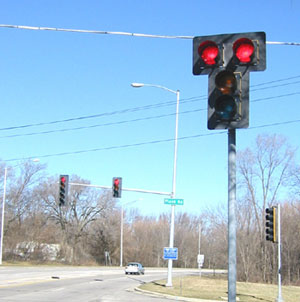
11.1.4 Use two Red Signal SectionsDescriptionThis treatment involves doubling the red signal indication on a signal head, which is permissible by the MUTCD (section 4D.16).(1) a possible arrangement is shown in figure 113. Note that the use a double red lens in any face does not eliminate the need for a second signal head with at least 2.4 m (8 ft) of horizontal separation between the two heads (section 4D.15).(1)
ApplicationThis treatment should be considered in situations where an unusually high number of angle collisions occur involving a red light running vehicle. Safety PerformanceTwo red signal sections in a single signal head will also increase the conspicuity of the red display and further increase the likelihood that the driver will see the signal. This improvement has had success in Winston-Salem, NC, where red "T" displays were associated with a drop in right-angle collisions (33 percent) and total collisions (12 percent).(135) Table 98. Safety benefits associated with using a double red indication (red "T") display: Selected findings.
Operational PerformanceThis treatment has a negligible effect on intersection capacity. Socioeconomic ImpactsThe additional cost of using two red signal sections is minimal. SummaryTable 99 summarizes the issues associated with using two red signal sections. Table 99. Summary of issues for using two red signal sections.
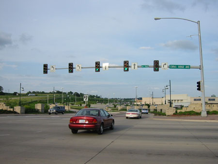
11.1.5 Increase Number of Signal HeadsDescriptionThe number of signal heads may be increased so one signal head is over each lane of traffic on an approach. Current MUTCD requirements for signal head placement state "a minimum of two signal faces shall be provided for the major movement on the approach, even if the major movement is a turning movement" (section 4D.15).(1) In addition, at least one signal head must be not less than 12 m (40 ft) beyond the stop line and not more than 55 m (180 ft) beyond the stop line unless a supplemental near-side signal face is provided. Finally, at least one and preferably both of the signal faces must be within the 20-degree cone of vision. Placement of traffic signal heads on a mast arm above each lane is commonly used. Figure 114 shows an example of an approach with dual left-turn lanes, two through lanes, and a right-turn lane with lane-aligned signal heads.
ApplicationThis treatment should be considered in situations where an unusually high number of angle collisions occur because a vehicle runs a red light. Safety PerformanceIncreasing the number of signal heads is expected to decrease the occurrence of red light running at an intersection in situations where driver fail to see a red signal. In one study in Winston-Salem, NC where such an improvement was undertaken, the addition of signal heads was associated with a decrease in right-angle collisions by 47 percent.(135) A Canadian study also found that adding a primary signal head decreased collisions of all severities; right-angle collisions dropped 15 to 45 percent.(168) However, the same Winston-Salem, NC study found that collisions increased overall by 15 percent.(135) This may be due to drivers unfamiliarity with such a treatment; more rear-end collisions may have occurred due to sudden braking on the approach as the indication turns red. Table 100 summarizes selected findings relating to the safety benefits of adding a signal head. Table 100. Safety benefits associated with addition of a signal head: Selected findings.
Operational PerformanceThis treatment has a negligible effect on intersection capacity. Socioeconomic ImpactsThe capital cost of adding an extra signal head is minimal if the existing mounting and pole can be used. If a new mast arm and/or pole is required, for instance, the costs could be significant. Additional maintenance and electricity costs are incurred over time. SummaryTable 101 summarizes the issues associated with adding a signal head. Table 101. Summary of issues for adding a signal head.
11.1.6 Provide BackplatesDescriptionBackplates are a common treatment for enhancing the visibility of a signal head. There are two main types of backplates:
ApplicabilityBoth types of backplates serve to increase the contrast between the signal head and its surroundings, drawing the attention of approaching drivers, therefore increasing the likelihood that they will stop on a red indication. Both should be used in situations where a high number of angle collisions occur. The two different types of backplates are used in very different applications. Black backplates may be useful on east-west approaches where the sun often is low in the sky, or against bright or confusing backgrounds. Conversely, yellow retroreflective tape on a backplate may be helpful to improve conspicuity, particularly at night. Operational FeaturesBackplates with a yellow retroreflective strip around the outside edge highlight the presence of the traffic signal. This is an advantage particularly during power outages. Safety PerformanceA study of black backplates in Winston-Salem, NC, found a 32-percent drop in right-angle collisions at intersections where backplates were installed.(135) A British Columbia study involving a comparison of collision frequency using the EB analysis before and after installation of backplates with a yellow retroreflective strip around the outside edge at a number of intersections concluded that they were effective at reducing the number of automobile insurance claims by 15 percent.(169) However, the Winston-Salem, NC study indicated that collisions appear to increase overall at intersections where black backplates were used.(135) The overall increase in collisions may be due to drivers' unfamiliarity with such a treatment, causing more rear-end collisions due to sudden braking on the approach as the indication turns red. A summary of selected findings into the safety benefits of the use of backplates is shown in table 102. Table 102. Safety benefits associated with the use of signal backplates: Selected findings.
Operational PerformanceThis treatment has a negligible effect on intersection capacity. Socioeconomic ImpactsThe cost of installing signal backplates on a signal head is minimal. In addition, extra wind loading caused by backplates may necessitate larger (more costly) support poles for both span wires and mast arms. Education/Enforcement/MaintenanceDue to their larger size, signal heads with backplates may be more prone to movement during high winds. This may pose a particular problem if they are mounted on a span wire, leading to maintenance issues. SummaryTable 103 summarizes the issues associated with using signal head backplates. Table 103. Summary of issues for using signal head backplates.
11.1.7 Provide Advance WarningDescriptionTwo treatments used to provide advance warning to motorists are those that:
Treatments that provide a general warning include static signs (SIGNAL AHEAD) and continuous advance-warning flashers. These flashers consist of a sign mounted on a pole with an amber flashing light. The sign may read bE PREPAREd tO STOP or show a schematic of a traffic signal. This type of flasher flashes regardless of what is occurring at the signal. Both treatments are placed upstream of the traffic signal at a distance sufficient to allow drivers time to react to the signal. The second type of treatment provides a specific warning of an impending traffic signal change ahead. These advance-warning flashers inform drivers of the status of a downstream signal. This type is activated showing yellow flashing lights or illuminating an otherwise blank changeable message such as "Red Signal Ahead" for several seconds. The sign and the flashers are placed a certain distance from the stop line as determined by the speed limit on the approach. ApplicabilityThe sIGNAL AHEAD sign and advance warning flasher are recommended by the MUTCD in cases were the primary traffic control is not visible from a sufficient distance to permit the driver to respond to the signal. Advance warning flashers may be an effective countermeasure for:
Advance-warning flashers are appropriate for high-speed, rural, isolated intersections where the signalized intersection may be unexpected or where there may be sight distance issues. They appear to be most beneficial in situations where the minor approach volumes exceed 13,000 AADT or greater. (170) Operational FeaturesA key factor in operating an advance-warning flasher is determining an appropriate time for coordinating the onset of flash with the onset of the yellow interval at the traffic signal. The recommended practice is to time the onset of flash as a function of posted speed for the distance from the flasher to the stop bar. Timing the onset of flash for speeds greater than the posted speed encourages speeding to clear the intersection before the onset of the red interval. Safety PerformanceThe introduction of advance-warning flashers on the approaches to a signalized intersection appears to be associated with a reduction in right-angle collisions. Right-angle collisions were reduced by 44 percent at 11 signalized intersections in where a SIGNAL AHEAD sign was installed on one or more approaches.(135) A study conducted in Minnesota involving the installation of an advance-warning flasher on one approach found a 29 percent reduction in the number of red light running events, in particular those involving trucks (63 percent). The study did not use a control or comparison group of intersection approaches.(171) Results from a study of 106 signalized intersections in British Columbia show that intersections with advance-warning flashers have a lower frequency of crashes than similar locations without flashers. The results were not statistically significant at the 95th-percent confidence level. Benefits were found primarily for moderate-to-high traffic volumes on the minor approach.(170) Table 104 shows selected references to safety benefits of advance-warning devices. Table 104. Safety benefits associated with advance warning signs and flashers: Selected findings.
Operational PerformanceAdvance warning flashers have no documented effect on intersection capacity. Multimodal ImpactsFlashers may be particularly useful for larger commercial vehicles, which need a greater distance to stop on intersection approaches. Socioeconomic ImpactsAdvance-warning flashers that activate before the onset of the yellow phase may be costly to install. Enforcement, Education, and maintenanceAnother study investigated the effect of advance flashing amber signs at two intersection approaches. Results showed that only a few drivers responded to the start of flashing by slowing down. The majority of vehicles increased their speed; many significantly exceeded the speed limit. Fifty percent of drivers who saw the flashing amber within the first 3 seconds it was displayed continued through the stop line. Driver education and police enforcement should be applied to ensure that drivers respond appropriately to signal-activated advance warning flashers.(173) SummaryTable 105 summarizes the issues associated with advance warning treatments. Table 105. Summary of issues related to advance warning treatments.
11.2 Signing and Speed Control Treatments11.2.1 Improve signingDescriptionFor some intersections, the use of signs beyond the minimum required by the MUTCD may be beneficial in improving either safety or operations.(1) ApplicationSigning treatments to consider at signalized intersections include:
Safety PerformanceNo studies are available to document specific benefits of the use of advance signing. Advance lane-use signs may improve safety by reducing last-minute lane changes. Selected findings of safety benefits of other types of improved signage at signalized intersections are shown in table 106. Table 106. Safety benefits associated with sign treatments: Selected findings.
Operational PerformanceAdvance lane use signing may improve lane utilization at the intersection and therefore improve capacity, if the affected movement is critical. Physical ImpactsSign supports are obstacles that could injure bicyclists, motorcyclists, pedestrians, and drivers.(62) Therefore, each sign should be carefully located to minimize the potential hazard. In addition, large advance signs can be difficult to locate in areas with tight right-of-way or where a sidewalk would be adversely affected by the sign or its support. Socioeconomic ImpactsAdvance signs, particularly if they are mounted overhead on a mast arm or sign bridge, can significantly add to the cost of the intersection. SummaryTable 107 summarizes the issues associated with improving signing. Table 107. Summary of issues for improving signing.
11.2.2 Reduce Operating SpeedExcessive speed on an approach may lead to drivers running a red light, braking suddenly to avoid a signal change, or losing control of the vehicle while attempting a left or right turn. Reducing the operating speed on an intersection approach cannot be accomplished through simply lowering the posted speed limit. Research suggests that drivers use the road and the surrounding road environment in choosing the operating speed of their vehicle, as opposed to a posted speed limit. Possible countermeasures that may reduce the operating speed of vehicles are landscaping, rumble strips, medians, narrow travel lanes, bike lanes, on-street parking, and curb radii reductions. Several of these treatments are discussed elsewhere in the guide; the reader is encouraged to refer to those sections for more information. 11.3 Roadway Surface improvements11.3.1 Improve Pavement SurfaceDescriptionAn important objective of highway design is ensuring that pavement is skid resistant and provides for adequate drainage. a polished pavement surface, a surface with drainage problems, or a poorly maintained road surface can contribute to crashes at or within intersections. Within an intersection, the potential for vehicles on adjacent approaches to be involved in crashes contributes to the likelihood of severe (angle) crashes, particularly in crashes where the driver is unable to stop in time. Water can accumulate on pavement surfaces due to rutted wheel paths, inadequate crown, and poor shoulder maintenance. These problems can also cause skidding crashes and should be treated when present. While there is only limited research on such site-specific programs, the results provide confidence that pavement improvements are effective in decreasing crashes related to wet pavement. The effectiveness will vary with respect to location, traffic volume, rainfall intensity, road geometry, temperature, pavement structure, and other factors Vehicles often experience difficulties in coming to a safe stop at intersections because of reduced friction on wet or slippery pavement. A vehicle will skid during braking and maneuvering when frictional demand exceeds the friction force that can be developed between the tire and the road surface; friction is greatly reduced on a wet and slippery surface, which has 20 to 30 percent less friction than a dry road surface.(175) Water pooling on or flowing across the roadway can prevent smooth operation of an intersection if vehicles are forced to decelerate or swerve in order to proceed safely through the intersection. It is necessary to intercept concentrated storm water at all intersection locations before it reaches the highway and to remove over-the-curb flow and surface water without interrupting traffic flow or causing a problem for vehicle occupants, pedestrians, or bicyclists. Improvements to storm drainage may be needed to improve intersection operations and safety. Potholes, if present on an approach, increase the likelihood of drivers swerving or braking to avoid damage to their vehicles. A rough surface may also allow water to pool, and in colder environments, can cause black ice to form on an intersection approach. Proper drainage and a high-quality surface will prevent problems related to pooled water and lack of skid resistance. Skid resistance is an important consideration in pavement design, and polished pavement surfaces should be addressed to reduce the potential for skidding. Both vehicle speeds and pavement condition affect the surface s skid resistance. Improving the pavement condition, especially for wet weather conditions, can be accomplished by providing adequate drainage, grooving existing pavement, or overlaying existing pavement. Improvements to pavement condition should have high initial skid resistance, ability to retain skid resistance with time and traffic, and minimum decrease in skid resistance with increasing speed. ApplicabilityImprovements related to skid resistance, drainage problems, and pavement surface should be considered when:
Safety PerformanceSeveral pavement treatments appear to reduce the number of skidding collisions. An early 1974 before-and-after study showed an 85 percent drop in wet pavement collisions after longitudinal grooving was applied to pavement.(176) Grooves carry off water from the road surface and increase the coefficient of friction between tires and pavement. Another more contemporary paper describes a noncarbonate surface treatment used at a wide range of sites as part of a comprehensive skid Accident Reduction program. Wet pavement collisions dropped by 61 to 82 percent; fatal and injury wet pavement collisions dropped by 73 to 84 percent.(177) It should be noted the collision reduction described in both studies includes both road segments and intersections. Apart from addressing wet road surface collisions, resurfacing the approaches to an intersection will likely reduce the number of rear-end or sideswipe collisions caused when vehicles swerve or slow to avoid potholes. It may, however, lead to a higher operating speed and an overall shift in the collision profile toward collisions of greater severity. References to safety benefits associated with nonskid treatments, drainage improvements or resurfacing are shown in table 108. Table 108. Safety benefits associated with nonskid treatments, drainage improvements, or resurfacing: Selected findings.
Operational Performancea pavement in poor condition can result in lower saturation flow rates and, consequently, reduce the capacity of the intersection. If vehicles need to proceed at slow speeds through an intersection or deviate from the travel path to avoid potholes, pooled water, or ice, operations likely will degrade. Pavement resurfacing and drainage improvements usually improve intersection operations, although no known research conclusively indicates the expected capacity benefit of these treatments. Multimodal ImpactsIf road improvements are being carried out, sidewalks and bike paths adjacent to the intersection should be considered for skid-resistant treatments, checked for adequate drainage, and repaired if uneven surfaces exist due to cracking, frost heaves, etc. This will reduce pedestrian tripping hazards and the likelihood of bicyclists swerving into traffic to avoid potential roadside hazards. Enforcement, Education, and maintenancePavement improvements (particularly resurfacing) may convey the message to drivers that they can now travel at higher speeds. Speeds on the approaches to the intersection should be monitored to ensure that the speed profile has not increased significantly in the post-implementation period. If speed has increased significantly and this is leading to degradation in safety, police speed enforcement should be considered. SummaryTable 109 summarizes the issues associated with pavement treatments. Table 109. Summary of issues for pavement treatments.
11.3.2 Provide Rumble stripsDescriptionRumble strips are warning devices that can be used to alert drivers to the presence of a traffic signal, thereby reducing the likelihood that the motorist will run a red light. They can also help reduce speeds on approaches. Rumble strips are a series of intermittent, narrow, transverse areas of rough-textured, slightly raised or depressed road surfaces. Rumble strips provide an audible and vibro-tactile warning to the driver. They are often used in conjunction with pavement markings. ApplicationRumble strips may be considered in rural areas, on approaches to signalized intersections where the traffic signal is not visible from a distance, and in situations where a high number of angle collisions occur. They generally result in too much noise in urban areas. Safety PerformanceRumble strips may reduce the likelihood of a right angle collision by alerting the driver to the traffic signal. References to safety benefits associated with rumble strips are shown in table 110. Table 110. Safety benefits associated with rumble strips: Selected findings.
Operational PerformanceThis treatment will increase the time headway between vehicles at an intersection, thus decreasing the capacity of the intersection and increasing delays and queuing. This will not be an issue if the application is for a high-speed rural intersection with lower volumes. However, the treatment may not be applicable to an urban intersection already experiencing congestion. Multimodal ImpactsRumble strips should not extend all of the way to the paved shoulder, because they would affect the safety of bicyclists traveling there. Socioeconomic ImpactsRumble strips may not be appropriate in residential areas due to the noise generated by vehicles traveling over them. SummaryTable 111 summarizes the issues associated with rumble strips. Table 111. Summary of issues for rumble strips.
11.3.3 Improve Cross sectionDescriptionRoadways should intersect on as flat a grade as possible to prevent difficulty in vehicle handling, especially when vehicles will likely need to wait for their turn to enter the intersection (as with left-turn lanes). However, it is not always feasible to design a level intersection, so consideration should be given to the profiles of the roadways as they intersect. The profiles and crowns of the roadways should be examined to determine whether the intersection of these slopes contributes to vehicle handling difficulties. Generally, the pavement of the minor road is warped so that the crown is tilted to the same plane as the major road profile. Another option is to flatten the cross sections of both roadways so that they are each inclined to intersect with the profile of the other road. This method can create a large pavement area, which in turn can lead to drainage problems; therefore, this design should only be used on smaller intersections or where the drainage problem can be solved. A third option involves maintaining constant cross sections on both roadways, and altering the centerline profiles to provide smooth pavement. This is a less desirable option than the previous two discussed, given that drivers from both directions must pass over three grade breaks at the intersection.(3) In addition to the benefits to vehicles, pedestrians and bicyclists benefit from improvements to the cross section of an intersection. Severe grades and cross slopes can be difficult for bicyclists and pedestrians to negotiate. For example, flatter uphill grades allow bicyclists to more easily accelerate from a complete stop. Low cross slopes of no more than 2 percent are essential for pedestrians with mobility impairments per ADAAG, as severe cross slopes can make a roadway inaccessible.(33) ApplicationThis treatment may be applicable at intersections where the grades of intersecting roads are greater than 3 percent and one or both of the following is true:
Safety PerformanceCross section improvements discussed above will improve sight distance, and therefore should decrease left-turn conflicts with through vehicles. It will also allow a more uniform operating speed through the intersection on the major road approaches, reducing rear-end conflicts. Operational PerformanceCross section improvements discussed above may reduce the time headway between vehicles and increase the capacity of the intersection. Multimodal ImpactsLarger commercial vehicles and transit buses will particularly benefit from cross section improvements to the intersection. If the intersection is being reconstructed, the engineer must include improvements to the adjacent sidewalks if pedestrian facilities exist and are being used. Social-economic impactsCross section improvements may have moderate costs. They may be difficult to implement in areas where there is little or no right-of-way. Coordination with adjacent landowners may be needed. Education/Enforcement/MaintenanceCross section improvements may convey the message that drivers can now travel at higher speeds. Speeds on the approaches to the intersection should be monitored to ensure that the speed profile has not increased significantly in the post-implementation period. If speed has increased significantly and this is leading to degradation in safety, police speed enforcement may be considered. Note that cross section improvements on hilly roadways may actually result in a reduction in speeds. The effectiveness of this treatment will likely be enhanced if performed in conjunction with a comprehensive and timely winter road maintenance program in colder climates. SummaryTable 112 summarizes the issues associated with cross section improvements. Table 112. Summary of issues for cross section improvements.
11.3.4 Remove Obstacles from Clear ZoneDescriptionRoadside objects can be a particular hazard to motorists on high-speed approaches. Utility poles, luminaires, traffic signal poles, bus shelters, signs, and other street furniture should be moved back from the edge of the road if possible and feasible. In general, a signalized intersection and the entire area within the right-of-way should be kept free of visual clutter, particularly illegally placed commercial signs. ApplicationObstacles should be routinely removed from the clear zone on intersection approaches. Removing objects should be considered an immediate priority when:
Safety PerformanceThis treatment should decrease the frequency of run-off-the-road injury and fatal collisions involving roadside obstacles. The number of collisions involving distracted drivers (such as rear-end collisions) should also decrease. Physical ImpactsMoving objects further away from the roadside may be difficult to implement in built-up areas where right-of-way is limited. Enforcement, Education, and maintenanceTraffic engineers should coordinate with their equivalents in the planning department and maintenance staff to ensure that the entire right-of-way surrounding the intersection and its approaches stays free of obstacles and extraneous signage. SummaryTable 113 summarizes the issues associated with removing obstacles from the clear zone. Table 113. Summary of issues for removing obstacles from the clear zone.
11.4 Sight Distance treatments11.4.1 Improve sight LinesDescriptionAdequate sight distance for drivers contributes to the safety of the intersection. In general, sight distance is needed for left-turning vehicles to see opposing through vehicles approaching the intersection in situations where a permissive left-turn signal is being used. Also, where right turns on red are permitted, right-turning vehicles need adequate sight distance to view vehicles approaching from the left on the cross street, as well as opposing vehicles turning left onto the cross street. AASHTO's a policy on Geometric Design of Highways and Streets recommends providing adequate sight distance for all movements at signalized intersections where the signal operates on flash at times.(3) Figure 115 shows sight distance triangles in each direction for drivers on the minor approach to an intersection.
Landscaping also must be carefully considered at signalized intersections, otherwise it will prevent motorists from making left and right turns safely due to inadequate sight distances. Care should be taken to ensure that traffic signs, pedestrian crossings, and nearby railroad crossing and school zones are not obstructed. Median planting of trees or shrubs greater than 0.6 m (2 ft) in height should be well away from the intersection (more than 15 m (50 ft)). No plantings having foliage between 0.6 m (2 ft) and 2.4 m (8 ft) in height should be present within sight triangles. Low shrubs or plants not exceeding a height of 0.6 m (2 ft) are appropriate on the approaches to a signalized intersection, either on the median, or along the edge of the roadway. The 1990 FHWA Guide, Vegetation Control for Safety: A Guide for Street and Highway Maintenance Personnel, provides additional guidelines and insight on vegetation control with regard to sight distance issues.(84) ApplicationVisibility improvements at a signalized intersections should be considered when:
Safety PerformanceIt is expected that crashes related to inadequate sight distance (specifically, angle- and turning-related) would be reduced if sight distance problems were improved. Intersections with sight distance problems will experience higher collision rates.(167) Older drivers are likely to have problems at intersections with limited sight distances, as they may need more time to perceive and react to hazards. Table 114 shows the expected reduction in number of collisions per intersection per year, based on an FHWA report.(180) Table 114. Expected reduction in number of crashes per intersection per year by increased sight distance.(180)
* Annual average daily traffic entering the intersection A more recent FHWA report cites sight distance improvements as being one of the most cost-effective treatments (see table 115). Fatal collisions were reduced by 56 percent and nonfatal injury collisions were reduced by 37 percent at intersections having sight distance improvements.(181) Table 115. Safety benefits associated with sight distance improvements: Selected findings.
Socioeconomic ImpactsSight distance improvements can often be achieved at relatively low cost by clearing sight triangles of vegetation or roadside appurtenances. The most difficult aspect of this strategy is the removal of sight restrictions located on private property. The legal authority of highway agencies to deal with such sight obstructions varies widely, and the time (and possibly the cost) to implement sight distance improvements by clearing obstructions may be longer if those obstructions are located on private property than if they are on public property. If the object is mature trees or plantings, then environmental issues may arise. Larger constructed objects (i.e., bus shelters, buildings) may not be feasibly removed. In these situations, other alternatives should be considered. Multimodal ImpactsThe appropriate use of landscaping can visually enhance a road and its surroundings. Landscaping may act as a buffer between pedestrians and motorists, and reduce the visual width of a roadway, serving to reduce traffic speeds while providing a more pleasant environment. However, landscaping should not interfere with the movement of pedestrians along sidewalks, nor should it block the motorist's view of the pedestrian, or the pedestrian's view of the motorist. Enforcement, Education, and maintenanceAll plantings should have an adequate watering and drainage system, or should be drought resistant. This will minimize the amount of maintenance required and reduce the exposure of maintenance staff to traffic. Plantings should not be allowed to obstruct pedestrians at eye height or overhang the curb onto the pavement. SummaryTable 116 summarizes the issues associated with visibility treatments. Table 116. Summary of issues for visibility improvements.
|
|||||||||||||||||||||||||||||||||||||||||||||||||||||||||||||||||||||||||||||||||||||||||||||||||||||||||||||||||||||||||||||||||||||||||||||||||||||||||||||||||||||||||||||||||||||||||||||||||||||||||||||||||||||||||||||||||||||||||||||||||||||||||||||||||||||||||||||||||||||||||||||||||||||||||||||||||||||||||||||||||||||||||||||||||||||||||||||||||||||||||||||||||||||||