U.S. Department of Transportation
Federal Highway Administration
1200 New Jersey Avenue, SE
Washington, DC 20590
202-366-4000
Federal Highway Administration Research and Technology
Coordinating, Developing, and Delivering Highway Transportation Innovations
 |
| This report is an archived publication and may contain dated technical, contact, and link information |
|
Publication Number: FHWA-HRT-08-053
Date: April 2008 |
||||||||||||||||||||||||||||||||||||||||||||||||||||||||||||||||||||||||||||||||||||||||||||||||||||||||||||||||||||||||||||||
Informational Report on Lighting Design for Midblock CrosswalksPDF Version (945 KB)
PDF files can be viewed with the Acrobat® Reader® ForewordThe overall goal of the Federal Highway Administration's (FHWA) Visibility Research Program is to enhance the safety of road users through near-term improvements of visibility on and along roadways. The program also promotes the cost-effective advancement of new practices and technologies to improve visibility. The following document summarizes the results of a series of studies that evaluated the visibility of pedestrians at nonintersection (midblock) crosswalks and provides information on lighting designs that will enhance the ability of drivers to detect those pedestrians. The research documented in FHWA-HRT-08-052 (NTIS publication number PB2008-106431), consisting of both static and dynamic experiments of driver performance, found that a vertical illuminance level in the crosswalk of 20 lx, measured at a height of 1.5 m (5 ft) from the road surface, provided adequate detection distances for most midblock crosswalks. This report will be of interest to traffic engineers, lighting designers, and city, State, and local authorities with responsibility for public safety. Michael F. Trentacoste Director, Office of Safety Research and Development Notice This document is disseminated under the sponsorship of the
U.S. Department of Transportation in the interest of information exchange. The
U.S. Government assumes no liability for the use of the information contained in this document. The
U.S. Government does not endorse products or manufacturers. Trademarks or manufacturers' names appear in this report only because they are considered essential to the objective of the document. Quality Assurance Statement The Federal Highway Administration (FHWA) provides high-quality information to serve Government, industry, and the public in a manner that promotes public understanding. Standards and policies are used to ensure and maximize the quality, objectivity, utility, and integrity of its information. FHWA periodically reviews quality issues and adjusts its programs and processes to ensure continuous quality improvement. Technical Report Documentation Page
Form DOT F 1700.7 (8-72) Reproduction of completed page authorized. Metric Conversion ChartTABLE OF CONTENTSChapter 3-Crosswalk Lighting Design Considerations LIST OF FIGURESFigure 1. Drawing. Vertical illuminance components. Figure 2. Equation. Vertical illuminance (EVert) at a height of 1.5 m (5 ft). Figure 3. Equation. Luminance of a diffusely reflecting surface. Figure 4. Equation. Weber Contrast. Figure 5. Equation. Weber Contrast (modified). Figure 6. Equation. Visibility level (VL). Figure 7. Photograph. Contrast of dark-clothed and light-clothed pedestrians. Figure 11. Drawing. Traditional midblock crosswalk lighting layout. Figure 12. Drawing. New design for midblock crosswalk lighting layout. Figure 13. Drawing. Traditional intersection lighting layout. Figure 14. Drawing. New design for intersection lighting layout for crosswalks. Figure 15. Drawing. New design for wide roadway intersection lighting
|
||||||||||||||||||||||||||||||||||||||||||||||||||||||||||||||||||||||||||||||||||||||||||||||||||||||||||||||||||||||||||||||
|
General Terms
|
|
|---|---|
| ANSI/IESNA RP-8 | America n National Standard Practice for Roadway Lighting |
| HPS | high-pressure sodium (lamp) |
| MH | metal halide (lamp) |
| Measurements | |
 |
visual angle (subtended by an object) |
| cd/m2 | candela per square meter |
| ft | feet |
| fc | footcandle |
| fL | footlambert |
| h | mounting height |
| lx | lux |
| m | meter |
| reflectance | |
| reflectance (of a specific object) | |
| Lighting Terms | |
| C | contrast |
| CActual | contrast (of a specific object) |
| CThreshold | threshold contrast |
| E | illuminance |
| EVert | vertical illuminance |
| I | luminous intensity |
| L | luminance |
| LAdaptation | adaptation luminance |
| LBackground | luminance (of the background) |
| LObject | luminance (of an object) |
| VL | visibility level |
Collisions between pedestrians and vehicles can occur at any point along a roadway and can be a result of pedestrian behavior, driver behavior, or both. A report of the Metropolitan Orlando Bicycle and Pedestrian Program notes that in an investigation of 617 pedestrian-vehicle crashes, 51.6 percent of this class of crashes happened at night with an even distribution between lighted roads and unlighted roads.(1) However, for fatal crashes, 58.6 percent occurred at night on unlighted roads and 25.3 percent occurred at night on lighted roads. The primary cause of these crashes appeared to be the lack of visibility of pedestrians as they crossed the road.
The purpose of this report is to provide information to traffic engineers and lighting designers regarding lighting parameters that impact the ability of drivers to see pedestrians in midblock crosswalks and to enable agencies to evaluate the potential effectiveness of lighting designs. While some visibility concepts are discussed below, this report does not cover all aspects of nighttime visibility and the human visual system. The information is based on static and dynamic experiments performed at the Virginia Tech Transportation Institute and documented in FHWA-HRT-08-052, available at NTIS under publication number PB2008-106431.
The initial static experiment used the time it took for an observer to detect the pedestrian or surrogate target as a metric for visibility, while the dynamic experiment used the distance at which pedestrians or surrogate targets were identified as the metric. Experimental condition variables included lamp type (high-pressure sodium, metal halide), vertical illuminance level (6, 10, 20, and 30 lx), color of pedestrian clothing (white, black, and denim), position of the pedestrians and surrogates, and the presence of glare.
Pedestrian visibility distance is the distance at which a driver can see a pedestrian well enough to be able to respond appropriately to the pedestrian's presence. The greater the visibility distance the more time a driver will have to react to the pedestrian before a conflict occurs.
Contrast is the difference between the visual appearance of an object of interest and the visual background against which that object is observed, and contrast is the basis of an object's visibility. Fundamentally, a crosswalk lighting designer's task is to maximize the contrast between pedestrians on or near the crosswalk and the visual background behind those pedestrians from the perspective of approaching drivers.
In general, there are two aspects of contrast-color contrast and luminance contrast. Color contrast is based on the difference in color between the object of interest and its background. For example, in daylight, a blue object can easily be seen against a green background even if the two areas have the same luminance. Luminance contrast, on the other hand, is based on a difference in the measured brightness of the object of interest and its background. Two objects of the same color may contrast sharply if one has a higher luminance than the other. At night, luminance contrast is the primary means by which an object is detected. Therefore, the basis for roadway lighting design is providing adequate luminance contrast.
Several factors affect the luminance contrast between pedestrians and their visual backgrounds: fixed roadway lighting, headlamp lighting, pedestrian clothing, and the characteristics of the visual backgrounds. Of these, only roadway lighting can be controlled by lighting designers. Headlamps are determined by vehicle manufacturers, clothing is chosen by pedestrians, and the objects and spaces that make up the visual background for drivers approaching a crosswalk are generally static. The lighting designer must react to but cannot change these basic characteristics.
Overhead road lighting installed at crosswalks generally provides greater visibility distance than headlamps alone to illuminate a scene. The effectiveness of overhead lighting in increasing visibility distance-by increasing luminance contrast-is a function of several variables: the location and orientation of the luminaire, the intensity of the emitted light, and the color of the light source.
Illuminance (E) is a measure of the amount of light that falls on a surface per unit area. The unit of illuminance is the lux or footcandle, where 1 fc = 10.76 lx. For practical considerations, the illuminance on a plane normal to the direction of propagation of light is equal to the luminous intensity (I) divided by the square of the distance. This is known as the inverse square law. When a surface of interest, such as the profile of a pedestrian, is canted relative to the normal of the direction of propagation, the available light is spread over a larger (projected) area. The illuminance on the projected area is equal to the illuminance on the plane normal to the direction of propagation times the cosine of the angle between the direction of propagation and the normal to the surface of interest.
Vertical illuminance (EVert) is defined as the illuminance on a vertical surface. The vertical illuminance on a pedestrian is the luminous intensity emitted by a luminaire in the direction of the pedestrian times the cosine of the angle between the direction of propagation and a horizontal line parallel to the road surface divided by the distance between the luminaire and the pedestrian. For roadway applications, the distance between a luminaire and the road surface is usually expressed as the mounting height (h) of the luminaire divided by the sine of the angle between the horizontal road surface and a line from the measurement point to the luminaire. A height of 1.5 m (5 ft) above the road surface was selected as the point at which the vertical illuminance on a pedestrian was measured, thus the distance between the luminaire and the measurement point for crosswalk lighting is the mounting height minus 1.5 m (5 ft) divided by the sine of the angle between a horizontal surface and a line to the luminaire. Figure 1 illustrates the components used to calculate the vertical illuminance on a pedestrian.
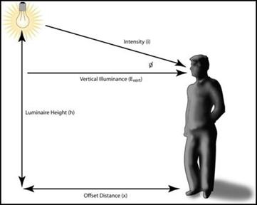
Figure 1. Drawing. Vertical illuminance components.
As figure 1 illustrates, the same angle  is used to calculate the vertical illuminance on the pedestrian and for the distance between the luminaire and the measurement point. Figure 2 provides the equation for the vertical illuminance on a pedestrian provided by a single luminaire.

Figure 2. Equation. Vertical illuminance (EVert) at a height of 1.5 m (5 ft).
Luminance (L) is the light emitted from a surface in a specific direction per unit area of the surface. (The light may be emitted, transmitted, or reflected from a real or imaginary surface.) The unit of luminance is the candela per square meter or footlambert, where 1 fL = 3.43 cd/m2. In terms of visual perception, an observer perceives luminance. It is an approximate description of how "bright" an object appears when viewed from a given direction. Brightness is a psycho-physical phenomenon that incorporates the appearance of the surrounding visual field and the observer's adaptation level with the luminance of the object. As an example, a full moon has the same measured luminance during day or night, but the moon appears brighter against a dark night sky. Brightness, however, is not used in calculating the visual appearance of an object; luminance and contrast are used instead.
Light incident on a surface is either absorbed or reflected. There are three types of reflection: specular, diffuse, and retroreflection. Under specular reflection, the light is reflected at an equal and opposite angle from the angle of incidence (both angles measured from the normal of the surface); diffuse reflection occurs when the light is reflected in all directions, with the amount of reflected light in any given direction proportional to the cosine of the angle between the direction of reflection and the normal of the surface; and retroreflection occurs when the light is reflected back toward the source of illumination. Although a pedestrian is not an ideal diffuse reflector, clothing tends to produce more diffuse reflection. Thus, the properties of a diffuse reflector are used to calculate the luminance of a pedestrian under roadway lighting. The general equation for the luminance of a diffuse reflector is shown in figure 3.

Figure 3. Equation. Luminance of a diffusely reflecting surface.
As discussed above, contrast is a measure of the visual difference of an object and its background. The most commonly used equation for describing contrast, as perceived by human observers, is Weber Contrast-the difference in two luminances divided by the lower luminance. In roadway lighting applications, a modified version of Weber Contrast is used, which is calculated as the difference in the luminance of the object of interest (LObject) and the background luminance (LBackground) divided by the background luminance (see figure 4).

Figure 4. Equation. Weber Contrast.
Note that the contrast can be either positive or negative, ranging from positive infinity to -1. Negative contrast is the condition where an object is darker than its background, thus the object appears in silhouette, whereas positive contrast is the condition where an object is brighter than its background.
By substituting a specific reflectance (![]() Object) and the vertical illuminance (EVert) for the general terms for calculating object luminance, contrast may be rewritten as shown in figure 5.
Object) and the vertical illuminance (EVert) for the general terms for calculating object luminance, contrast may be rewritten as shown in figure 5.
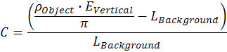
Figure 5. Equation. Weber Contrast (modified).
In this formula, the object reflectance (![]() Object) is determined by the pedestrian's clothing selection, the vertical illuminance on the pedestrian (EVert) is provided by a roadway luminaire, and the background luminance (LBackground) is determined by the environment and the placement of the crosswalk in the roadway. Vertical illuminance is the only parameter directly selected by the lighting designer. Although a public agency has little influence over pedestrians' clothing selections, high clothing reflectance will certainly improve detection. The research showed that the visibility of a pedestrian dressed in white clothing was unaffected by a change in lighting level whereas the visibility of a person dressed in denim clothing was impacted by the different lighting conditions. Other research has shown the same results.(2,3) Although it is not part of this informational report on crosswalk lighting design, public outreach regarding high clothing reflectance may benefit pedestrian safety.
Object) is determined by the pedestrian's clothing selection, the vertical illuminance on the pedestrian (EVert) is provided by a roadway luminaire, and the background luminance (LBackground) is determined by the environment and the placement of the crosswalk in the roadway. Vertical illuminance is the only parameter directly selected by the lighting designer. Although a public agency has little influence over pedestrians' clothing selections, high clothing reflectance will certainly improve detection. The research showed that the visibility of a pedestrian dressed in white clothing was unaffected by a change in lighting level whereas the visibility of a person dressed in denim clothing was impacted by the different lighting conditions. Other research has shown the same results.(2,3) Although it is not part of this informational report on crosswalk lighting design, public outreach regarding high clothing reflectance may benefit pedestrian safety.
An object in the visual field has a theoretical threshold contrast (luminance contrast at which the object may be just detected(4)). Threshold contrast is a function of the visual size of the object (typically described by the visual angle, , of the object), the length of observation time, the adaptation luminance (LAdaptation) of the observer, and the age of the observer. An object at threshold contrast has a probability of detection of 50 percent. Therefore, to ensure reliable detection of objects or pedestrians on or along the roadway, lighting conditions must provide an actual contrast that is greater than the threshold contrast. The ratio of the actual contrast to threshold contrast is defined as the visibility level (VL). VL provides a measure of the visibility conditions and is used as a means to evaluate the performance of lighting installations. In the case of a crosswalk, a higher VL for a given condition indicates that a pedestrian is more easily seen than an installation with a lower VL. The equation for VL is shown in figure 6.

Figure 6. Equation. Visibility level (VL).
VL can be modified by changes in the threshold contrast or the actual contrast. However, many of the factors from which threshold contrast is derived are not controllable. The age of the observer and the observation time cannot be changed, and neither can the visual size of the object, which is determined by the distance from the observer to the object of interest. This means that adaptation luminance and actual contrast are the only values that may be manipulated to modify VL.
For roadway applications, background luminance, which is dominated by the luminance of the road surface, is considered to be the adaptation luminance of the observer. Therefore, manipulating the background luminance changes both the threshold contrast and the actual contrast, as shown in figure 5 and figure 6. In the situation where an object is seen in positive contrast (object luminance is greater than the background luminance), increasing the background luminance will increase the threshold contrast while decreasing actual contrast. This results in a reduction of VL. For crosswalks, where the lighting system used to illuminate the pedestrians also illuminates the road surface, a balance must be struck between the level of roadway (background) luminance that is generated and the vertical illuminance provided for pedestrian visibility.
Two other aspects of contrast that must be considered when calculating the visibility of an object on or along the roadway are the polarity of the contrast and the consistency of the contrast across the object.
As mentioned above, contrast can be either negative or positive. Typically an object is more easily detected in negative contrast, and at distances greater than 100 m (330 ft), the road luminance (background) is usually higher than the luminance of most objects found on or along the road. At distances less than 30 m (100 ft), however, the increasing vertical illuminance provided by vehicle low-beam headlamps will result in an object having a higher luminance than the roadway. For the range 30-100 m (100-330 ft), the contrast polarity will depend on several factors, including the presence of fixed roadway lighting, the reflectance of the road surface, the reflectance of the object, and the intensity profile of the vehicle's headlamps. Because it is difficult or impossible for a lighting system to maintain a given level of negative contrast, it is generally considered good practice to establish a lighting system that results in adequate positive contrast to detect pedestrians at a distance that will provide adequate response time.
The second aspect of contrast that should be considered is the consistency of contrast across the object. In actual roadway situations, a given object typically has a varying contrast. The contrast can change from negative to positive as well as vary in magnitude. In figure 7, the pedestrian in dark clothing appears in negative contrast from the feet up to the knees, at which point the contrast changes to positive-the black clothing appears lighter than the background. In comparison, the lighter-clothed pedestrian appears in negative contrast only at the feet and in positive contrast for the rest of the body. Both of these aspects of pedestrian contrast should be considered when designing a crosswalk lighting system.
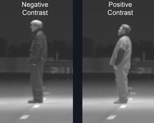
Figure 7. Photograph. Contrast of dark-clothed and light-clothed pedestrians.
The background for most crosswalks consists of the roadway and the environment surrounding the roadway. Bright roadway surfaces or bright off-roadway installations such as gas stations, banks, or shopping areas increase background luminance and reduce contrast, making pedestrian detection more difficult. One of the difficulties for pedestrian detection is that background luminance is not consistent. The background is also dependent on the driver's perspective while approaching the crosswalk. In figure 8, a crosswalk is shown at distances of 61 m (200 ft) and 305 m (1,000 ft) from a vehicle. Red arrows indicate a pedestrian in the crosswalk. Here it can be seen that the background against which the pedestrian is viewed changes as the vehicle approaches the crosswalk. At 305 m (1,000 ft) the pedestrian is primarily seen against the environment around the roadway (sky and unlighted distant background), whereas at 61 m (200 ft) the lower half of the pedestrian is seen against the bright background of a lighted roadway. A lighting design level should be selected to provide adequate performance even with a bright background. Typically, the brighter the background, the higher the vertical illuminance required for a driver to clearly see a pedestrian in the crosswalk.
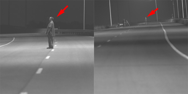
Figure 8. Photograph. Visual background for a pedestrian at 61 m (200 ft)
and at 305 m (1,000 ft) from a vehicle.
The research considered midblock crosswalk locations and found that a vertical illuminance level of 20 lx in the crosswalk, measured at a height of 1.5 m (5 ft) from the road surface, provided adequate detection distances.
It was found that a cylinder, 1.8 m tall (5 ft 10 inches) and 0.30 m (12 inches) in diameter with an 18-percent reflectance, suitably represented a pedestrian for visualization and use in computer programs.
In designing a crosswalk lighting system, selecting an appropriate luminaire and luminaire height are critical. Since the object of interest is vertical, the intensity distribution should have a horizontal component. If all the light from the luminaire is directed downward, the vertical profile of the pedestrian will not be adequately illuminated.
The luminous intensity distribution from the luminaire must be able to provide the required luminous intensity in the geometry required. If the luminaire cannot produce the required intensity, it is not suitable for use in a crosswalk installation.
The suitability of a luminaire can be determined using a lighting design program. In figure 9, a 250-W high-pressure sodium (HPS) luminaire, mounted at a height of 8.5 m (28 ft), is located at the bottom left corner of a 0.3 m by 0.3 m (1 ft by 1 ft) grid. The vertical illuminance was calculated at each grid point across the road and downstream from the luminaire. The results are illustrated using an iso-illuminance plot on a plan view of the road. The two vertical lines indicate that the desired vertical illuminance of 20 lx may be found for a crosswalk located at a distance of 4.25-6 m (14-20 ft) from the luminaire position.
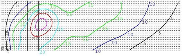
Figure 9. Plot. Vertical illuminance plot for a 250-W HPS flat lens cobra-head-style
luminaire mounted at 8.5 m (28 ft).
The same luminaire used at a different height may not be suitable. In figure 10, the same luminaire is mounted at a height of 10 m (33 ft) from the road surface. As illustrated, the vertical illuminance levels do not reach the desired level of 20 lx.
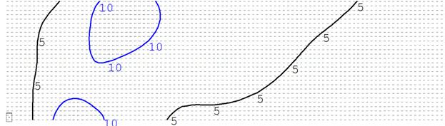
10. Plot. Vertical illuminance plot for a 250-W HPS flat lens cobra-head-style luminaire mounted at 10 m (33 ft).
Another criterion that should be used in selecting the luminaire is the width of the area that meets the required 20 vertical lux. Twenty vertical lux provided across the entire roadway enables an oncoming vehicle to detect a pedestrian before he or she steps into the roadway lane. Figure 9 illustrates that the luminaire under evaluation provides 20 vertical lux only across a width of
5.8 m (19 ft) at a distance of 5 m (16.5 ft) from the luminaire position. This may be acceptable for a two-lane road without shoulders or a median but inadequate for wider facilities.
Testing a variety of combinations of mounting heights and luminaire types will allow an agency to establish standard recommendations for typical crosswalk scenarios. The most cost-effective method may be to use different luminaires and different mounting heights than are typically used by an agency for continuous roadway lighting.
Another consideration in the design of the lighting system is related to the use of breakaway features: agencies should follow the guidance outlined in the American Association of State Highway and Transportation Officials Roadsign Design Guide regarding the selection and of breakaway or non-breakaway luminaire supports.(5)
Many agencies have historically installed a single luminaire directly over the crosswalk as shown in figure 11. While this provides high pavement luminance at the crosswalk, it does not adequately illuminate the pedestrian. The luminaires should be located such that the vertical illuminance on the pedestrian makes him or her visible at a sufficient distance. Based on the assessment performed to select the luminaire, the luminaire should be located so that it provides 20 vertical lux at the crosswalk. In the installation defined in figure 11, the luminaire should be located at least 3 m (10 ft) from the crosswalk. This luminaire location is simulated in figure 12.
Note that for roadways that have traffic traveling in both directions, particularly those without a center median, two luminaires are required, located on either side of the road and placed prior to the crosswalk from the drivers' perspective. This is also shown in figure 12.

Figure 11. Drawing. Traditional midblock crosswalk lighting layout.
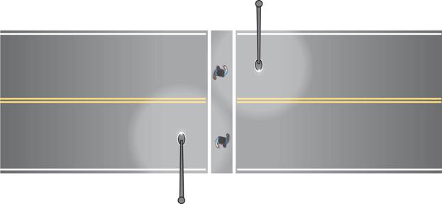
Figure 12. Drawing. New design for midblock crosswalk lighting layout.
Because the influence of other lighting fixtures on background luminance must also be considered, the final aspect of the design is the location of the crosswalk within the cycle of luminaires on lighted roadways. When a lit road surface is viewed from a vehicle, the pavement surface luminance is not uniform. The brightest pavement areas are located between the driver and the luminaires providing light. The road surface luminance increases as a driver approaches a luminaire and then drops as the luminaire is passed, and a crosswalk is viewed against this varying background. If possible, the crosswalk should be located within the cycle of luminaires such that the roadway luminance does not significantly change the contrast of the pedestrian as the vehicle approaches the crosswalk.
With respect to the designated crosswalk lighting luminaires, the crosswalk should be located to provide the desired level of vertical illuminance at the crosswalk for all travel directions. If possible, the subsequent luminaire in a continuous lighting layout along a given direction of travel should be located at least 10 times farther away from the crosswalk; this mitigates the changes in background luminance associated with the viewing perspective. This spacing criterion does not affect the placement of the luminaire provided to light the crosswalk for the opposite direction of travel. Note that it may be necessary to modify the standard pole spacing to properly light the crosswalk, especially in retrofit applications.
Requirements for lighting crosswalks may be modified based on certain aspects of roadway design. Glare, intersections, different lamp types, and high ambient lighting locations all influence the specifics of the lighting design.
Glare is experienced when the luminance from a light source in the visual field is much higher than the luminance to which the eye is adapted. Two types are defined: discomfort glare and disability glare. Discomfort glare occurs when a person experiences discomfort or even pain when viewing a light source. Disability glare limits the ability of an observer to perform a visual task, which in the case of crosswalk lighting is pedestrian detection. One of the purposes of providing roadway and crosswalk lighting is to mitigate disability glare.
The most common source of glare experienced by drivers is approaching headlamps from an opposing vehicle. In the research, the glare condition was simulated by placing an opposing vehicle between the observer and the crosswalk. While increasing the vertical illuminance did not have a statistically significant impact, there was a clear trend for improvement in the pedestrian detection distance in the presence of glare as the vertical illuminance was increased. Areas where drivers may experience higher levels of disability glare than normal may require vertical illuminance levels greater than 20 lx.
HPS and metal halide (MH) lamps are the two most commonly used sources for roadway lighting. HPS produces an amber light, while MH produces a white or bluish-white light. While HPS is used for most roadway applications because of its high efficiency and long life, there are claims that MH may provide a safety benefit because it improves driver peripheral vision. The periphery of the eye is more sensitive to the spectra provided by MH than to the spectra provided by HPS at typical roadway lighting levels.
The research did not show large differences in detection of a black-clothed pedestrian under HPS and MH lighting. However, pedestrians dressed in denim were detected at longer distances under MH lighting.
The same lighting level is recommended for MH and HPS light sources. As shown in other research, MH sources should be considered. White light will provide a higher level of facial recognition and comfort to the users of the roadway. Similarly, a color difference between continuous roadway lighting and crosswalk lighting may highlight the presence of the crosswalk.
Most crosswalks are colocated with intersections. Because of various constraints, the present research was limited to evaluating the lighting levels that allow detection of pedestrians at midblock crosswalks. Although no specific research has been performed that addresses the higher background luminance typically found at intersections and the greater cognitive demands on drivers as they approach an intersection, a level of 30 vertical lux is considered a conservative estimate of the lighting level required for adequate visibility.
ANSI/IESNA RP-8 recommends that lighting at intersections of roads with continuous roadway lighting should equal the sum of the light levels for each separate road.(6) This results in a higher background luminance for a crosswalk on the approach side of the intersection (the crosswalk closest to the driver as he or she enters the intersection) than the background luminance for the other crosswalks in the intersection. For the approach-side crosswalk, a higher lighting level should be considered to mitigate the impact of the background luminance on contrast. This means that in a two-road intersection with a crosswalk at each leg, the outer sides of the crosswalks should be illuminated to a higher level than the interior side of the same crosswalk.
A typical intersection lighting design is shown in figure 13. Here, luminaires are positioned to provide the high level of pavement illuminance required in the intersections and to light the potential conflict areas for the vehicles. This design lights the side of the pedestrian facing the intersection and does not light the side of the pedestrian facing the approaching vehicle. In order to provide for positive contrast of the pedestrian, the luminaires should be located away from the intersection to provide light on the approach side of the pedestrian as shown in figure 14. As also shown in figure 14, the roadway lighting luminaires provide vertical illuminance on the approach side of the pedestrian, which is augmented by the vehicle headlamps.
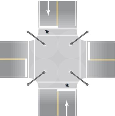
Figure 13. Drawing. Traditional intersection lighting layout.
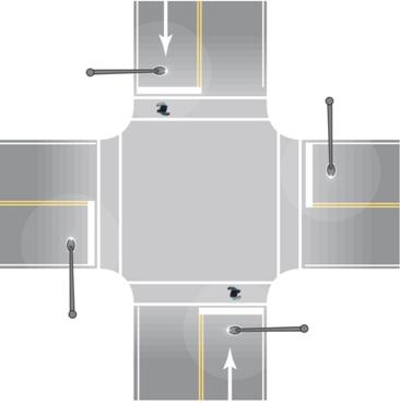
Figure 14. Drawing. New design for intersection lighting layout for crosswalks.
Another consideration for intersections are wide roadways. It is possible that two approach luminaires may be required to provide the required illuminance level across the entire roadway. A luminaire located in the center median may be required for the design, as shown in figure 15. Care must be taken to ensure that the requirements of the appropriate agency are not violated, as luminaires located in the center median may violate roadway clear zones and present an additional hazard to drivers. If placing a luminaire in the median is not an option, a wide throw luminaire (Type III) might be able to be used from the roadway edge to light other lanes.
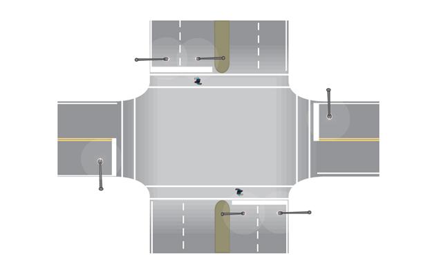
Figure 15. Drawing. New design for wide roadway intersection lighting layout for crosswalks.
Similar to crosswalks located at intersections, crosswalks that have high ambient lighting in the background may benefit from a higher vertical illuminance. These areas would include crosswalks close to shopping areas, adjacent to transit stations, and in central business districts. While no specific research has been performed to address this issue, a vertical illuminance level of 30 lx is considered a conservative estimate of the lighting level required for adequate visibility.

