U.S. Department of Transportation
Federal Highway Administration
1200 New Jersey Avenue, SE
Washington, DC 20590
202-366-4000
Federal Highway Administration Research and Technology
Coordinating, Developing, and Delivering Highway Transportation Innovations
 |
| This report is an archived publication and may contain dated technical, contact, and link information |
|
Publication Number: FHWA-HRT-09-039
Date: April 2010 |
||||||||
Pavement Marking Demonstration Project: State of Alaska and State of Tennessee-Report to CongressAppendix B. Pavement Marking Test deckDdesignsPrevious | Table of Contents | Next Transverse Test DecksTransverse test decks are the field method used by NTPEP. NTPEP test decks are located around the country, and the data are pooled to be used by any transportation agency. The procedures for conducting a test deck are based on the ASTM D 713 standard. This procedure calls for the site to have the following characteristics: (See references 48-50.)
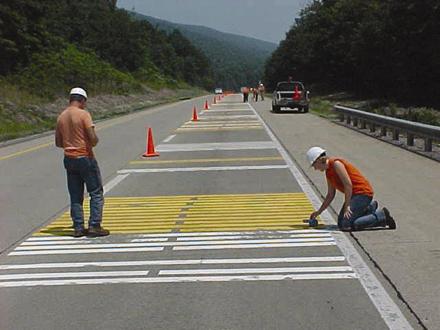
Transverse test decks are installed using the protocol established in ASTM D 713 and by the NTPEP standards and best practices.(48) This protocol indicates the design of the test deck, appropriate installation conditions, and when and how to collect data after installation. An example of an NTPEP transverse test deck is given in figure 18 (photograph courtesy of the Pennsylvania Department of Transportation), and an example of a transverse test deck in Alaska is given in figure 19 (photograph courtesy of the Alaska Department of Transportation and Public Facilities). Long-Line Test DecksLong-line test decks are installed in the same location and direction as standard pavement markings. This allows the markings to be placed under typical circumstances, and they are subjected to normal traffic conditions. Long-line test decks give realistic installation and wear conditions to the markings. These conditions provide an environment where durability can be accurately measured and monitored. Long-line test decks do not have a protocol for test location, installation conditions, or data collection procedures. This can lead to variations in design from one test deck to another, which may lead to variations in results between studies. These variations are typical when normal pavement markings are applied to roadways.
Figure 18. Photo. Typical transverse test deck.
Figure 19. Photo. Transverse test deck in Alaska. As part of this research, a standalone paper comparing the results of the transverse and longitudinal test decks will be produced. A summary of the advantages and disadvantages of each test desk design can be found in table 33 and table 34. Test Deck SummaryBoth transverse and long-line test decks have advantages and disadvantages. Each method of pavement marking testing can provide useful information depending on the information being sought after. Table 33. Advantages and disadvantages of transverse test decks.
Table 34. Advantages and disadvantages of long-line test decks.
|