U.S. Department of Transportation
Federal Highway Administration
1200 New Jersey Avenue, SE
Washington, DC 20590
202-366-4000
Federal Highway Administration Research and Technology
Coordinating, Developing, and Delivering Highway Transportation Innovations
 |
| This report is an archived publication and may contain dated technical, contact, and link information |
|
Publication Number: FHWA-HRT-04-145
Date: December 2005 |
|||
Enhanced Night Visibility Series, Volume XIV: Phase III—Study 2: Comparison of Near Infrared, Far Infrared, and Halogen Headlamps on Object Detection in Nighttime RainPDF Version (929 KB)
PDF files can be viewed with the Acrobat® Reader® APPENDIX F—AIMING PROTOCOLPull the vehicle/headlamp cart up to the alignment plate mounted onto the ground. This should be located 35 feet from the alignment wall. Make sure the wheels are straight against the plate. Use the laser to make sure the target board is centered to the vehicle/headlamp cart. Each headlamp has a different line on the target board. The lines are labeled directly on the target board. Locate the appropriate markings on the target board for each headlamp. Turn on the appropriate headlamps, making sure no auxiliary lights (parking lights, fog lights, daytime running lights) are on. Cover up or unplug one headlamp so that you are only taking readings for one light at a time.
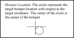
Finding the Hotspot: Align the VES so that the “hotspot” is located in the first (or lower right) quadrant, tangent to both the horizontal and vertical lines. The sensor, when measuring the hotspot in that quadrant, will touch both axes of the crosshairs. The headlamps have both gross and fine adjustments. Typically, only fine adjustments will be required if the headlights are not switched; gross will be required if the headlights are switched.
Note: Why do we align these lights off-center point? When these types of lights are aligned straight ahead, the lights are placed in a “High Beam” configuration. We do not want to use the “High Beam” configuration in this study. Our alignment procedure allows each light to be directed slightly to the right and below the exact centerline for that light
Using the Photometer: To determine if the hotspot is in the correct location, you will need to use the International Light, Inc.®, IL1400A Radiometer/Photometer to measure the area of greatest intensity. There are two sensors for the photometer; the sensor for the visible light is marked with a “REG” label, and the sensor for the UV light is marked with a “UV–A” label. Use the sensor marked “REG.”
Zero the Photometer: Remember to “ZERO” the photometer prior to checking each measurement. To do this, make sure that all headlamps are turned off. Remove the cap from the photometric sensor. Place the sensor at the alignment location for the headlamp to be aligned. Press the “ZERO” button; this will allow the photometer to measure any undesired background light and remove its effects from the actual light source value. The photometer is ready when the “ZEROING” message has changed back to the “SIGNAL” message. Turn the headlamp on and begin alignment.
Isolating the Hotspot: Once you find the area you believe has the highest intensity, readings need to be taken in all directions around that location to ensure that is the hotspot. If the hotspot is in the correct location, the headlamp is aligned and you can align the other headlamp(s).
Note that for non-UV headlamps, the HLBs in particular, the hotspots actually span a large horizontal swath, 2-4 inches wide. It is relatively easy to determine the hotspot vertically, but determining the hotspot horizontally requires more effort and patience given that the horizontal hotspot can be 2-4 inches wide.
Special Instructions for HID alignment: Remember that the HIDs require alignment with the photometer for rightmost (no. 2) headlamp and visual alignment based of the left (no. 1) headlamp based on the aligned right headlamp. This is noted on the alignment form. Each headlamp has its own diagram located on the server in the Disability Glare/Headlamps folder.
|