U.S. Department of Transportation
Federal Highway Administration
1200 New Jersey Avenue, SE
Washington, DC 20590
202-366-4000
Federal Highway Administration Research and Technology
Coordinating, Developing, and Delivering Highway Transportation Innovations
 |
| This report is an archived publication and may contain dated technical, contact, and link information |
|
Publication Number: FHWA-HRT-04-148
Date: December 2005 |
|||||
Enhanced Night Visibility Series, Volume XVII: Phases II and III—Characterization of Experimental Vision Enhancement SystemsPDF Version (5.65 MB)
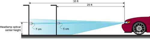
PDF files can be viewed with the Acrobat® Reader® CHAPTER 3—HEADLAMP AIMING PROCEDURESThe aiming of the headlamps in this project was a critical component of the ENV vehicle setup. The repeatability of the aim for a headlamp was vital to the reduction of uncertainty caused by the lighting conditions. The general methods for the aiming of all of the headlamps in the project are provided in appendix A. Specific methods are shown in each of the ENV experimental reports. The headlamps used for the HLB, HID, HOH, HHB, and UV–A VES configurations were located on external light bars. For the HLB and the HID light sources, the VESs were moved onto, off of, and between vehicles to change from one configuration to the next. Each light assembly movement required a re-aiming process, which took place before starting the experimental session each night. Headlamps are designed so that the system may be either visually optically aligned (VOA) or mechanically aimed. At the beginning of the ENV project, a headlamp aimer was not available, so an aiming protocol that could be used with either type of system was developed with the help of experts in the field. (See references 5, 6, 7, 8, and 9.) The method used for this project is a modified version of the typical SAE aiming method. The aiming method required the selection of a reference point and then the aiming of the headlamp beam relative to that reference point. No standard is available for the aiming of UV–A headlamps, so a similar method was selected for these headlamp types. For this procedure, an alignment board was placed 10.7 m (35 ft) from the experimental vehicle. This distance, which is a departure from the 7.6-m (25-ft) vehicle distance used by the SAE methodology, was selected during the original ENV process and maintained throughout the investigation for all of the aimed headlamps. The 10.7-m (35-ft) distance was the maximum possible in the aiming area at the contractor's facility. A comparison of alignment at the two distances was performed to ensure validity of the methodology. The alignment board was marked with each headlamp system's reference points, which were chosen following SAE J599, 1997.(10) The horizontal position (side to side) of the reference point was directly in front of the vehicle coincident with the vertical optical centerline of the headlamp (usually denoted on the headlamp as a circle or a cross etched into the lens). The vertical position (up and down) of the reference point depended on the height of the experimental vehicle. The SAE specifies that if the optical center of the headlamp, or optical center height (OCH), is less than 90 cm (36 inches) above the roadway surface, then the reference point should be at the same height as the optical center. If the optical center is more than 90 cm (36 inches) above the roadway surface, the reference point should be 5 cm (2 inches) below the headlamp optical center. These reference points were adjusted for the greater alignment distance.(10) Figure 6 shows a comparison between the 7.6-m (25-ft) and 10.7-m (35-ft) alignment distances. The units, a mix of English and the International System of Units, are prescribed by the SAE guidelines. Figure 6. Diagram. Comparison of vertical reference point for 25-ft and 35-ft
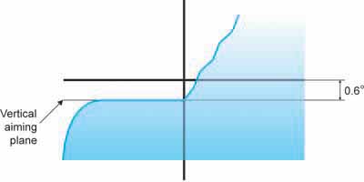
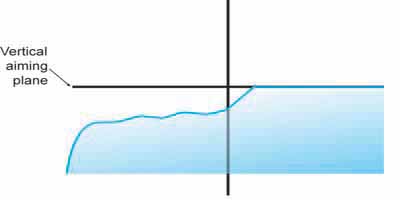
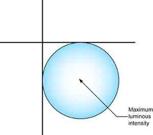
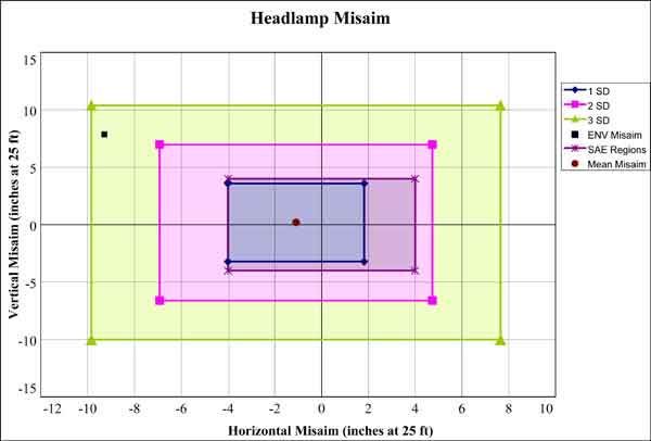
headlamp alignment distances. VISUALLY OPTICALLY ALIGNED AIMINGThere are two subtypes of the visually optically aligned (VOA) systems, visually optically aligned left (VOL) and visually optically aligned right (VOR). VOL headlamps are aimed so that the sharp cutoff of the light pattern on the left of the lamp is aimed to a vertical aiming plane. VOR headlamps are aimed using the right portion of the beam as the reference. VOL systems have a vertical aiming plane 0.6° below the vertical reference point on the alignment board. VOR systems have a vertical aiming plane at the same height as the reference point. Figure 7 and figure 8 show the aiming planes used. MECHANICALLY AIMED HEADLAMP AIMINGThe HLB, HOH, and HHB headlamps used in this study were mechanically aimed systems. With this type of headlamp, the reference for the position of the headlamp is based on three aiming pads located on the lens of the luminaire. These pads and measurements shown on the headlamp are used with a mechanical aiming device. Optical aimers that analyze the beam pattern and set the maximum luminous intensity of the headlamp beam to a specified location also can be used to aim this type of headlamp. For this investigation, neither an optical aimer nor a mechanical aimer was available. It was decided that an illuminance meter with a remote sensor would be used to find the maximum luminous intensity of the beam, and then the headlamps would be aimed so that this maximum point was located at a selected point relative to the reference point. As with the VOA headlamps, the reference point was chosen as specified by SAE J599, 1997.(10) The point selected for the maximum luminous intensity of the beam was at 2.5 cm (1 inch) to the right and 2.5 cm (1 inch) below this reference point at the 10.7-m (35-ft) alignment distance. The sensor element of an illuminance meter was positioned at this point while the headlamp was slowly adjusted to determine the orientation at which the maximum luminous intensity of the beam (hotspot) was directed toward the selected point (figure 9). During the measurements made as part of this characterization, it was discovered that this is not the typical location for the maximum luminous intensity of the beam. Although not an exact specification, SAE 1383, 1996, shows that the maximum allowable luminous intensity of the beam should be located approximately 1.5° down and 2° to the right of the reference point (table 3A of SAE 1383 1996).(11) At 10.7 m (35 ft), these dimensions translate to 27.9 cm (11 inches) down and 37.2 cm (14.7 inches) to the right, the location used by optical aimers.(9) This means that the aiming of the HLB, HOH, and HHB all have a deviation of approximately 1.36° above and 1.77° to the left of the typical point of maximum luminous intensity. This deviation was consistent across all of the studies performed with these headlamps. To investigate the magnitude of this deviation, a review of the literature was undertaken, and two sources were found: the SAE standard and a fleet misaim investigation performed by Copenhaver and Jones.(12) In the SAE J599 1997 standard, an allowance of 10 cm (4 inches) of variance was defined around the reference point at an alignment distance of 25 ft (7.62 m). This means the HLB, HOH, and HHB aiming points used in this study were 0.6 degrees above and 1.0 degrees to the left of the extreme upper left position defined by the SAE aiming variance guidelines.(10) Copenhaver and Jones investigated the typical amount of misaim found in the vehicle population to establish the variability that exists in the real world.(12) In this study, the headlight aim of 768 vehicles was measured. The mean result for misaim was 0.36 cm (0.143 inches) up and 2.01 cm (0.82 inches) left for the left headlamp and 0.59 cm (0.23 inches) up and 3.46 cm (1.36 inches) left for the right headlamp. The standard deviation (SD) of these measurements was 8.71 cm (3.43 inches) vertically and 7.14 cm (2.81 inches) horizontally for the left headlamp and 8.56 cm (3.37 inches) vertically and 7.67 cm (3.02 inches) horizontally for the right headlamp. Note that these dimensions refer to a misaim at the typical aiming distance of 7.6 m (25 ft). The misaim in the ENV project was within three standard deviations of the mean of this data. Figure 10 shows the ENV misaim in relation to the Copenhaver and Jones data and the SAE allowable misaim. In this figure, the (0,0) reference point is the proper aiming location. The blue, pink, and green areas refer to one, two, and three standard deviations, respectively, according to the Copenhaver and Jones data, and the purple box is the SAE variance region. It can be seen that the aiming point used in the ENV investigation is within the third standard deviation area of the Copenhaver and Jones data. Figure 10. Graph. Misaim from the Copenhaver and Jones data.(12)
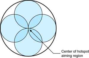
The effect of this aiming variance on the results of the visibility experiments varied for each study. For the HLB and the HOH lamp types, the selected aim point likely resulted in greater illumination at points farther down the road, which in turn may have increased the detection distances and glare ratings. The HHB aiming may have actually reduced the amount of light reaching the objects on the roadway and reflected back to the observers, possibly decreasing the detection distances and glare ratings; however, it is not known what effect the aiming had on the results for the various weather conditions tested (ENV Volumes IV, V, VI, and XIV). UV–A HEADLAMP AIMINGAs mentioned, there is no standard method for aiming UV–A headlamps. The method developed for this project was to aim each headlamp straight ahead of the vehicle. The reference points were selected in a similar method to the visible light headlamps. During the aiming process, a UV–A radiance meter was used to find the maximum radiant intensity output from the headlamp. Because of the headlamp mounting mechanism, a wider margin of error was selected for the UV–A headlamps; the hotspot was then aimed within 5 cm (2 inches) of the reference point. The aiming region is shown in figure 11.
|