Lesson 11: Pedestrian Design at Intersections
Lesson Outline
- Intersection design principles.
- Purpose and design of crosswalks, curb ramps, technology, half-signals, curb extensions, pushbuttons, refuge islands, and roundabouts.
Intersection Design Principles
- Encourage crossing at intersection corners.
- Make pedestrians visible to traffic.
- Make vehicular traffic visible to pedestrians.
- Encourage predictable pedestrian actions.
- Ease movement to street level.
- Minimize crossing distance.
- Slow vehicular traffic.
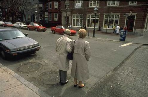
Reduced Visibility
Alternative Design
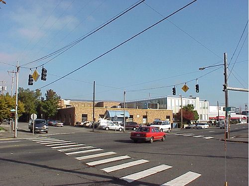
Use of Crosswalks
- Purpose:
| – Control pedestrian movements. |
| – Promote a connected pedestrian network. |
| – Improve visibility of a crossing place. |
- Design Issues:
| – Location. |
| – Marking types. |
| – Lighting. |
| – Maintenance. |
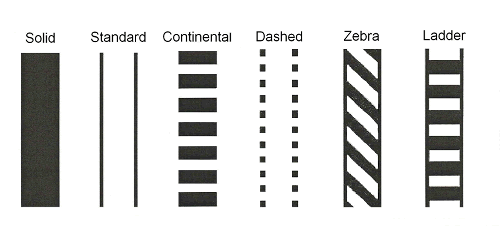
Common Crosswalk Types
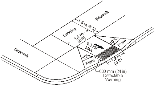
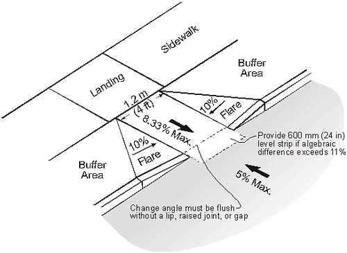
Use of Curb Ramps
- Purpose:
| – Provide access for wheelchair users, strollers, luggage, handcarts, etc. |
- Design Issues:
| – Location. |
| – Slopes. |
| – Flat landing area. |
| – Obstructions in or near the ramp. |
| – Width. |
Curb Ramp Slopes
Slope and Counter Slope
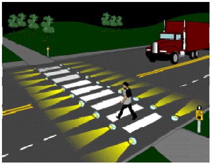
Use of Crossing and Detection Technology
- Purpose:
| – Provide visibility to crossing. |
| – Encourage and assist pedestrian crossings. |
- Design Issues:
| – Which treatment to use (lighting, flags, green signs, flashing beacons, staggered pedestrian crossings, etc.) and where to use? |
In-Roadway Warning Lights
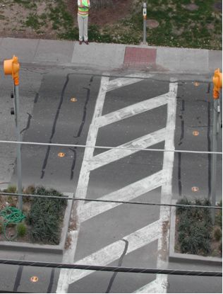
Use of Pedestrian Half-Signals
- Purpose:
| – Assist pedestrian crossings on high-volume, unsignalized intersections along arterials. |
- Design Issues:
| – If delay > 30 seconds, pedestrians will cross on their own. |
| – Adjust timing for pedestrian walking speeds. |
| – Place pedestrian signal heads on channelized islands. |
| – Provide audible signals where necessary. |
Example of Half-Signal
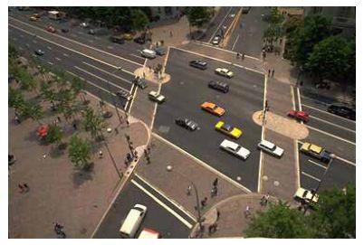
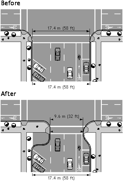
Use of Curb Extensions
- Purpose:
| – Shorten pedestrian crossing distance. |
| – Shorten pedestrian signal phase. |
| – Allow pedestrians to see the traffic better. |
| – Allow traffic to see the pedestrians. |
- Design Issues:
| – Corner radius length. |
| – How far to extend into the street? |
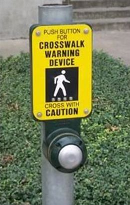
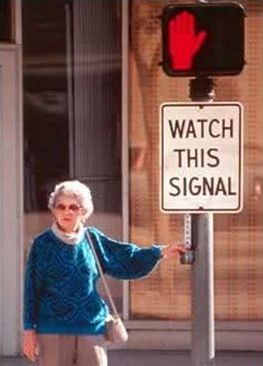
Use of Signal Timing and Pushbuttons
- Purpose:
| – Stop vehicular traffic and provide pedestrian crossing phase. |
- Design Issues:
| – Location (near ramps, in medians, etc.). |
| – Lights (like an elevator call button) to indicate actuation of the pushbutton. |
| – Quick response time to actuation. |
| – WALK/DON'T WALK signal phase timing. |
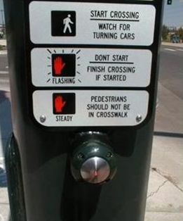
Pushbuttons
| Source: PBIC, www.pedbikeimages.org |
Use of Pedestrian Refuge Islands
- Purpose:
| – Provide a safe resting/waiting area for pedestrians. |
| – Allow pedestrians to cross only one direction of traffic at a time. |
- Design Issues:
| – Accessible path through island. |
| – Offset crosswalks to orient crossing pedestrians to oncoming traffic. |
| – Minimum dimensions—1.8 meters (m) long by 3.7 m wide (12 feet (ft) long by 6 ft wide). |
| – Highly visible approach nose. |
| – Guide strips for the visually impaired. |
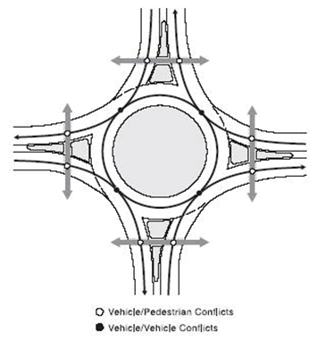
Use of Roundabouts
- Purpose:
| – Lower vehicular speeds. |
| – Reduce the number of conflict points. |
| – Shorten crossing distances and waiting times. |
- Design Issues:
| – Marked versus unmarked crosswalks. |
| – Accessibility for visually impaired pedestrians. |
| – Splitter islands. |
| – Discouraging pedestrians from crossing to the center island. |
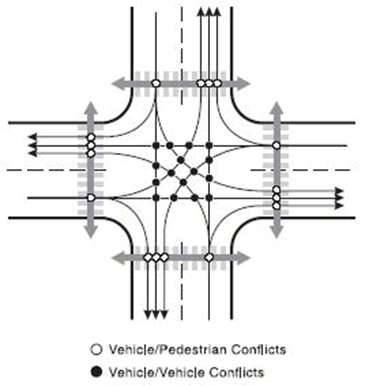
Conflict Points at Intersections
Lesson Summary
- Pedestrians can be accommodated even at wide, high-volume intersections.
- A wide variety of design elements exist to make good pedestrian design possible at intersections.
FHWA-HRT-05-106
|