

Comprehensive Design Example for Prestressed Concrete (PSC) Girder Superstructure Bridge
Design Step 6.0 - Steel-Reinforced Elastomeric Bearing Design
Design requirements (S14.5.3)
Movements during construction
Where practicable, construction staging should be used to delay construction of abutments and piers located in or adjacent to embankments until the embankments have been placed and consolidated. Otherwise, deck joints should be sized to accommodate the probable abutment and pier movements resulting from embankment consolidation after their construction.
Closure pours may be used to minimize the effect of prestress-induced shortening on the width of seals and the size of bearings.
Characteristics (S14.6.2)
The bearing chosen for a particular application has to have appropriate load and movement capabilities. Table S14.6.2-1 may be used as a guide when comparing different bearing systems.
Force effects resulting from restraint of movement at the bearing (S14.6.3)
Restraint forces occur when any part of a movement is prevented. Forces due to direct loads include dead load of the bridge and loads due to traffic, earthquakes, water and wind. The applicable limit states must be considered.
Bearings are typically located in an area which collects large amounts of dirt and moisture and promotes problems of corrosion and deterioration. As a result, bearings should be designed and installed to have the maximum possible protection against the environment and to allow easy access for inspection.
Elastomeric bearing overview
Shore A Durometer hardnesses of 60±5 are common, and they lead to shear modulus values in the range of 80 to 180 psi. The shear stiffness of the bearing is its most important property since it affects the forces transmitted between the superstructure and substructure. Some states use a slightly different common range than stated above. See S14.7.5.2 and S14.7.6.2 for material requirements of neoprene bearing pads.
Elastomer may be used as a plain pad (PEP) or may be reinforced with steel. Steel reinforced elastomeric bearings are composed of layers of elastomer and steel plates bonded together with adhesive.
Elastomers are flexible under shear and uniaxial deformation, but they are very stiff against volume changes. This feature makes the design of a bearing that is stiff in compression but flexible in shear possible. Under uniaxial compression, the flexible elastomer would shorten significantly and, to maintain constant volume, sustain large increases in its plan dimension, but the stiff steel layers of the steel reinforced elastomeric bearings restrain the lateral expansion.
Elastomers stiffen at low temperatures. The low temperature stiffening effect is very sensitive to the elastomer compound, and the increase in shear resistance can be controlled by selection of an elasotmer compound which is appropriate for the climatic conditions.
The design of a steel reinforced elastomeric bearing requires an appropriate balance of compressive, shear and rotational stiffnesses. The shape factor, taken as the plan area divided by the area of the perimeter free to bulge, affects the compressive and rotational stiffnesses, but it has no impact on the translational stiffness or deformation capacity.
The bearing must be designed to control the stress in the steel reinforcement and the strain in the elastomer. This is done by controlling the elastomer layer thickness and the shape factor of the bearing. Fatigue, stability, delamination, yield and rupture of the steel reinforcement, stiffness of the elastomer, and geometric constraints must all be satisfied.
Design methods
Two design methods are allowed by the AASHTO-LRFD Specifications. Method A, specified in S14.7.6, is applicable to plain, steel reinforced and fiber glass reinforced elastomeric pads as well as cotton duck pads. Method B, specified in S14.7.5, is applicable to steel reinforced elastomeric bearings. The following sections and the design example below are based on Method B. Flowcharts for the bearing design using both Method A and Method B are included in Section 3.
General elastomer material properties and selection criteria (S14.7.5.2)
Commonly used elastomers have a shear modulus between 0.080 and 0.175 ksi and a nominal hardness between 50 and 60 on the Shore A scale. The shear modulus of the elastomer at 73° F is used as the basis for design. The elastomer may be specified by its shear modulus or hardness. If the elastomer is specified explicitly by its shear modulus, that value is used in design, and other properties are obtained from Table S14.7.5.2-1. If the material is specified by its hardness, the shear modulus is taken as the least favorable value from the range for that hardness given in Table S14.7.5.2-1. Intermediate values may be obtained by interpolation.
Elastomer grade is selected based on the temperature zone of the bridge location and by Table S14.7.5.2-2. The temperature zones are shown in Figure 6-1.
Table S14.7.5.2-2 - Low-Temperature Zones and Minimum Grades of Elastomer
| Low-Temperature Zone | A | B | C | D | E |
|---|---|---|---|---|---|
| 50-year low temperature (oF) | 0 | -20 | -30 | -45 | -45 |
| Maximum number of consecutive days when the temperature does not rise above 32oF | 3 | 7 | 14 | NA | NA |
| Minimum low-temperature elastomer grade | 0 | 2 | 3 | 4 | 5 |
| Minimum low-temperature elastomer grade when special force provisions are incorporated | 0 | 0 | 2 | 3 | 5 |
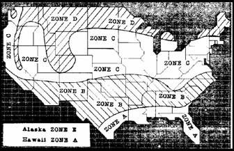
Figure 6-1 - Temperature Zones
According to S14.7.5.2, any of the three design options listed below may be used to specify the elastomer:
Specify the elastomer with the minimum low-temperature grade indicated in Table S14.7.5.2-2 and determine the shear force transmitted by the bearing as specified in S14.6.3.1;
Specify the elastomer with the minimum low-temperature grade for use when special force provisions are incorporated in the design but do not provide a low friction sliding surface, in which case the bridge shall be designed to withstand twice the design shear force specified in S14.6.3.1; or
Specify the elastomer with the minimum low-temperature grade for use when special force provisions are incorporated in the design but do not provide a low friction sliding surface, in which case the components of the bridge shall be designed to resist four times the design shear force as specified in S14.6.3.1.
Design Step 6.1 - Design a steel reinforced elastomeric bearing for the interior girders at the intermediate pier
A typical elastomer with hardness 60 Shore A Durometer and a shear modulus of 150 psi is assumed. The 1.75 ksi delamination stress limit of Eq. S14.7.5.3.2-3 requires a total plan area at least equal to the vertical reaction on the bearing divided by 1.75. The bearing reaction at different limit states is equal to the shear at the end of Span 1 as shown in Tables 5.3-3 and -4. These values are shown in Table 6-1 below.
Table 6-1 - Design Forces on Bearings of Interior Girders at the Intermediate Pier
Max. factored reaction (k) Max. reaction due to LL (k) Strength I 433.0 1.75(129.9) Service I 290.5 129.9
Notice that:
The loads shown above include the dynamic load allowance. According to the commentary of S14.7.5.3.2, the effect of the dynamic load allowance on the elastomeric bearing reaction may be ignored. The reason for this is that the dynamic load allowance effects are likely to be only a small proportion of the total load and because the stress limits are based on fatigue damage, whose limits are not clearly defined. For this example, the dynamic load allowance (33% of the girder maximum response due to the truck) adds 21.64 and 37.88 kips to the girder factored end shear at the Service I and Strength I limit states, respectively. This is a relatively small force, therefore, the inclusion of the dynamic load allowance effect leads to a slightly more conservative design.
The live load reaction per bearing is taken equal to the maximum girder live load end shear. Recognizing that the girder, which is continuous for live load, has two bearings on the intermediate pier, another acceptable procedure is to divide the maximum live load reaction on the pier equally between the two bearings. This will result in lower bearing loads compared to using the girder end shear to design the bearings. This approach was not taken in this example, rather, the girder end shear was applied to the bearing.
Design Step 6.1.1 - Determine the minimum bearing area
The bearing at the intermediate pier is fixed and is not subject to shear deformation due to the lack of movements. According to S14.7.5.3.2, the maximum compressive stress limit under service limit state for bearings fixed against shear deformations:
σs ≤ 2.00GS ≤ 1.75 ksi (S14.7.5.3.2-3)
σL ≤ 1.00GS (S14.7.5.3.2-4)
where:
σs = service average compressive stress due to the total load (ksi) σL = service average compressive stress due to live load (ksi) G = shear modulus of elastomer (ksi) S = shape factor of the thickest layer of the bearing
To satisfy the 1.75 ksi limit, the minimum bearing area, Areq, should satisfy:
Areq > 290.5/1.75 = 166.0 in2
The corners of the bottom flanges of the girder are usually chamfered. The bearing should be slightly narrower than the flat part of the flange unless a stiff sole plate is used to insure uniform distribution of the compressive stress and strain over the bearing area. The bearing should be as short along the length of the girder as practical to permit rotation about the transverse axis. This requires the bearing to be as wide as possible which is desirable when stabilizing the girder during erection. For a first estimate, choose a 24 in. width [28 in. wide girder bottom flange - 2(1 in. chamfer + 1 in. edge clearance)] and a 7.5 in. longitudinal dimension to ensure that the maximum compressive stress limit is satisfied (area = 24(7.5) = 180 in2 > 166 in2 required OK). The longitudinal translation is 0 in. for a fixed bearing. Notice that for a bearing subject to translation, i.e., movable bearing, the shear strains due to translation must be less than 0.5 in./in. to prevent rollover and excess fatigue damage. This means that the total elastomer thickness, hrt, must be greater than two times the design translation, Δs, where applicable. A preliminary shape factor should be calculated according to S14.7.5.1.
Design Step 6.1.2 - Steel-reinforced elastomeric bearings - Method B (S14.7.5)
For bridges at locations where the roadway has positive or negative grade, the thickness of the bearing may need to be varied along the length of the girder. This is typically accomplished through the used of a tapered steel top plate. In this example, the bridge is assumed to be at zero grade and, therefore, each elastomer and reinforcement layer has a constant thickness. All internal layers of elastomer shall be of the same thickness. For bearings with more than two elastomer layers, the top and bottom cover layers should be no thicker than 70 percent of the internal layers.
The shape factor of a layer of an elastomeric bearing, Si, is taken as the plan area of the layer divided by the area of perimeter free to bulge. For rectangular bearings without holes, the shape factor of the layer may be taken as:
Si = LW/[2hri(L + W)] (S14.7.5.1-1)
where:
L = length of a rectangular elastomeric bearing (parallel to the longitudinal bridge axis) (in.) W = width of the bearing in the transverse direction (in.) hri = thickness of ith elastomeric layer in elastomeric bearing (in.)
Determine the thickness of the ith elastomeric layer by rewriting Eq. S14.7.5.1-1 and solving for hri due to the total load.
hri = LW/[2Si(L + W)]
Design Step 6.1.2.1 - Design Requirements (S14.7.5.3)
Compressive stress (S14.7.5.3.2):
In any elastomeric bearing layer, the average compressive stress at the service limit state will satisfy the following provisions.
These provisions limit the shear stress and strain in the elastomer. The relationship between the shear stress and the applied compressive load depends directly on the shape factor, with higher shape factors leading to higher capacities.
First, solve for the shape factor under total load, STL, by rewriting Eq. S14.7.5.3.2-3 for bearings fixed against shear deformation.
STL ≥ σs/2.00G (S14.7.5.3.2-3)
where:
σs = PTL/Areq PTL = maximum bearing reaction under total load (k)
= 290.5 kσs = 290.5/[7.5(24)]
= 1.614 ksiG = 0.150 ksi
| STL | ≥ 1.614/[2.00(0.150)] ≥ 5.38 (1) |
Solve for the shape factor under live load, SLL, by rewriting Eq. S14.7.5.3.2-4 for bearings fixed against shear deformation.
SLL ≥ σL/1.00G (S14.7.5.3.2-4)
where:
σL = PLL/Areq PLL = maximum bearing live load reaction (k)
= 129.9 kσL = 129.9/[7.5(24)]
= 0.722 ksi
| SLL | ≥ 0.722/[1.00(0.150)] ≥ 4.81 (2) |
From (1) and (2), the minimum shape factor of any layer is 5.38.
Notice that if holes are present in the elastomeric bearing their effect needs to be accounted for when calculating the shape factor because they reduce the loaded area and increase the area free to bulge. Use Eq. SC14.7.5.1-1 in this case instead of Eq. S14.7.5.1-1.
Using the shape factors of STL and SLL calculated above, determine the elastomer thickness.
| hri(TL) | < (LW)/[2(STL)(L + W)] < 7.5(24)/[2(5.38)(7.5 + 24)] < 0.531 in. |
and
| hri(LL) | < (LW)/[2(SLL)(L + W)] < 7.5(24)/[2(4.81)(7.5 + 24)] < 0.594 in. |
Use an interior elastomer layer thickness of hri = 0.5 in.
The shape factor is:
| S | = (LW)/[2(hri)(L + W)] = 7.5(24)/[2(0.5)(7.5 + 24)] = 5.71 |
Design Step 6.1.2.2 - Compressive deflection (S14.7.5.3.3)
This provision need only be checked if deck joints are present on the bridge. Since this design example is a jointless bridge, commentary for this provision is provided below, but no design is investigated.
Deflections of elastometric bearings due to total load and live load alone will be considered separately.
Instantaneous deflection is be taken as:
Δ = σeihri (S14.7.5.3.3-1)
where:
εi = instantaneous compressive strain in ith elastomer layer of a laminated bearing hri = thickness of ith elastomeric layer in a laminated bearing (in.)
Values for εi are determined from test results or by analysis when considering long-term deflections. The effects of creep of the elastomer are added to the instantaneous deflection. Creep effects should be determined from information relevant to the elastomeric compound used. In the absence of material-specific data, the values given in S14.7.5.2 may be used.
Design Step 6.1.2.3 - Shear deformation (S14.7.5.3.4)
This provision need only be checked if the bearing is a movable bearing. Since the bearing under consideration is a fixed bearing, this provision does not apply. Commentary on this provision is provided below, but no design checks are performed.
The maximum horizontal movement of the bridge superstructure, Δo, is taken as the extreme displacement caused by creep, shrinkage, and posttensioning combined with thermal movements.
The maximum shear deformation of the bearing at the service limit state, Δs, is taken as Δo, modified to account for the substructure stiffness and construction procedures. If a low friction sliding surface is installed, Δs need not be taken to be larger than the deformation corresponding to first slip.
The bearing is required to satisfy:
hrt ≥ 2Δs (S14.7.5.3.4-1)
where:
hrt = total elastomer thickness (sum of the thicknesses of all elastomer layers) (in.) Δs = maximum shear deformation of the elastomer at the service limit state (in.)
This limit on hrt ensures that rollover at the edges and delamination due to fatigue will not take place. See SC14.7.5.3.4 for more stringent requirements when shear deformations are due to high cycle loading such as braking forces and vibrations.
Design Step 6.1.2.4 - Combined compression and rotation (S14.7.5.3.5)
Service limit state applies. Design rotations are taken as the maximum sum of the effects of initial lack of parallelism between the bottom of the girder and the top of the superstructure and subsequent girder end rotation due to imposed loads and movements.
The goal of the following requirements is to prevent uplift of any corner of the bearing under any combination of loading and corresponding rotation.
Rectangular bearings are assumed to satisfy uplift requirements if they satisfy:
σs > 1.0GS(θs/n)(B/hri)2 (S14.7.5.3.5-1)
where:
n = number of interior layers of elastomer, where interior layers are defined as those layers which are bonded on each face. Exterior layers are defined as those layers which are bonded only on one face. When the thickness of the exterior layer of elastomer is more than one-half the thickness of an interior layer, the parameter, n, may be increased by one-half for each such exterior layer. hri = 0.5 in. σs = maximum compressive stress in elastomer (ksi)
= 1.614 ksiB = length of pad if rotation is about its transverse axis or width of pad if rotation is about its longitudinal axis (in.)
= 7.5 in.θs = maximum service rotation due to the total load (rads) For this example, θs will include the rotations due to live load and construction load (assume 0.005 rads) only. As a result of camber under the prestressing force and permanent dead loads, prestressed beams typically have end rotation under permanent dead loads in the opposite direction than that of the live load end rotations. Conservatively assume the end rotations to be zero under the effect of the prestressing and permanent loads.
= 0.005944 rads (from a live load analysis program)
Rewrite Eq. S14.7.5.3.5-1 to determine the number of interior layers of elastomer, nu, for uplift:
| nu | > 1.0GS(θs)(B/hri)2/σs > 1.0(0.150)(5.71)(0.005944)(7.5/0.5)2/1.614 > 0.710 |
To prevent excessive stress on the edges of the elastomer, rectangular bearings fixed against shear deformation must also satisfy:
σs < 2.25GS[1 - 0.167(θs/n)(B/hri)2] (S14.7.5.3.5-3)
Rewrite Eq. S14.7.5.3.5-3 to determine the number of interior layers of elastomer, nc, required to limit compression along the edges.
| nc | > -0.167(θs)(B/hri)2/[σs/2.25GS - 1] > -0.167(0.005944)(7.5/0.5)2/[1.614/[2.25(0.150)(5.71)] - 1] > 1.37 |
Use 2 interior layers 0.5 in. thick each. Use exterior layers 0.25 in. thick each (< 70% of the thickness of the interior layer).
Design Step 6.1.2.5 - Stability of elastomeric bearings (S14.7.5.3.6)
Bearings are investigated for instability at the service limit state load combinations specified in Table S3.4.1-1.
Bearings satisfying Eq. S14.7.5.3.6-1 are considered stable, and no further investigation of stability is required.
2A ≤ B (S14.7.5.3.6-1)
for which:
where:
L = 7.5 in.
W = 24 in.
hrt = total thickness of the elastomer in the bearing (in.)
= 2(0.25) + 2(0.5)
= 1.5 in.
For a rectangular bearing where L is greater than W, stability will be investigated by interchanging L and W in Eqs. S14.7.5.3.6-2 and -3.
= 0.301
= 0.321
Check 2A ≤ B
2(0.301) = 0.602 > 0.321, therefore, the bearing is not stable and Eqs. S14.7.5.3.6-4 and -5 need to be checked.
For bridge decks fixed against translation, the following equation needs to be satisfied to ensure stability.
σs ≤ GS/(A - B) (S14.7.5.3.6-5)
However, if A - B ≤ 0, then the bearing is considered stable.
A - B = 0.301 - 0.321 = -0.02
Therefore, the bearing is stable.
Design Step 6.1.2.6 - Reinforcement (S14.7.5.3.7)
The reinforcement should sustain the tensile stresses induced by compression on the bearing. With the present load limitations, the minimum steel plate thickness practical for fabrication will usually provide adequate strength.
At the service limit state:
hs ≥ 3hmaxσs/Fy (S14.7.5.3.7-1)
where:
hmax = thickness of thickest elastomeric layer in elastomeric bearing (in.)
= 0.5 in.σs = 1.614 ksi Fy = yield strength of steel reinforcement (ksi)
= 36 ksi
| hs(TL) | ≥ 3(0.5)(1.614)/36 ≥ 0.067 in. |
At the fatigue limit state:
hs ≥ 2.0hmaxσL/ΔFTH (S14.7.5.3.7-2)
where:
hmax = 0.5 in. σL = 129.9/[7.5(24)]
= 0.722 ksiΔFTH = constant amplitude fatigue threshold for Category A as specified in Table S6.6.1.2.5-3 (ksi)
= 24 ksi
| hs(LL) | ≥ 2(0.5)(0.722)/24 ≥ 0.030 in. |
Use hs = 0.120 in. thick steel reinforcement plates; this is an 11 gage shim.
If holes exist in the reinforcement, the minimum thickness is increased by a factor equal to twice the gross width divided by the net width. Holes in the reinforcement cause stress concentrations. Their use should be discouraged. The required increase in steel thickness accounts for both the material removed and the stress concentrations around the hole.
The total height of the bearing, hrt:
| hrt | = cover layers + elastomer layers + shim thicknesses = 2(0.25) + 2(0.5) + 3(0.120) = 1.86 in. |
Figure 6-2 - Dimensions of Elastomeric Bearing
Notes:
- 11 gage steel shim thickness is held constant for all bearings
- All cover layers and edge covers are to be 1/4-inch thick.
- Total bearing thickness will include the summation of a masonry plate, a sole plate, and the laminated elastomeric pad thickness.
- Elastomer in all bearings shall have grade 60 Shore A Durometer hardness.
- Pad shall be vulcanized to masonry plate and sole plate in the shop
- Pad thickness shown is uncompressed.
A shear key between the bent cap and the concrete diaphragm will provide the movement restraint in the longitudinal direction. See Figure 6-3.
Figure 6-3 - Longitudinal Fixity at Intermediate Bent