U.S. Department of Transportation
Federal Highway Administration
1200 New Jersey Avenue, SE
Washington, DC 20590
202-366-4000
California Division

OBJECTIVE: The high-level design defines the project level architecture of the system. This architecture defines the sub-systems to be built, internal and external interfaces to be developed, and interface standards identified. The high level design is where the sub-system requirements are developed. The high-level design also identifies the major candidate off-the-shelf products that might be used in the system. |
DESCRIPTION: High-level design is the transitional step between WHAT [requirements for sub-systems] the system does, and HOW [architecture and interfaces] the system will be implemented to meet the system requirements. This process includes the decomposition of system requirements into alternative project architectures and then the evaluation of these project architectures for optimum performance, functionality, cost, and other issues [technical and non-technical]. Stakeholder involvement is critical for this activity. In this step, internal and external interfaces are identified along with the needed industry standards. These interfaces are then managed throughout the development process. The following uses ramp metering as an example for the two key decomposition activities: Functional decomposition is breaking a function down into its smallest parts. [E.g., ramp metering includes the sub-functions of detection, meter rate control, main line metering, ramp queuing, time of day, and communications]. Physical decomposition defines the physical elements needed to carry out the function. [E.g., ramp metering decomposition includes loops, controller clock, fiber or twisted pair for communications, 2070 controllers, host computers, cabinets, and conduits]. Finally, allocating these sub-functions to the physical elements of the system will form the complete project architecture. This step also defines the integration and verification activities needed when the system elements are developed. |
CONTEXT OF PROCESS:
HIGH LEVEL DESIGN PROCESS |
Inputs: System Requirements are used as the primary source for the project level architecture. Concept of Operations provides user requirements and context to the sub-systems requirements. System Verification Plan will provide context information for sub-system verification [what the sub-system needs to do to meet the system verification]. This augments the system level requirements. |
Control: Project Plan / Systems Engineering Management Plan [SEMP] defines the process for developing the design. Configuration Management Plan defines the process for managing changes to requirements. Risk management monitors, controls, and mitigates high risk factors of the High Level Design, architectures, requirements, and technology. |
Enablers: Elicitation supports this process, which is essential to developing a system that meets stakeholder needs. Technical reviews support continuing communications with the stakeholders, which are essential to developing a concept that reflects their needs within the stakeholders organization and operations. Trade studies are used to analyze design alternatives and to select among them. Stakeholder involvement is needed to validate the sub-system requirements and architecture. Traceability for architecture elements and sub-system requirements to system level requirements and other supporting documents, such as standards, to ensure compliance and completeness. |
Outputs: High Level Design [project architecture] is documented, and controlled moving forward into detailed design. Internal and external interface specifications that will need to be managed. Selected industry standards that are recommended for the High Level Design. Sub-system Requirements and Sub-system Verification Plans from the requirements/verification process |
Process Activities: Develop, decompose, and evaluate project architecture/High Level Design [HLD] alternatives Systems engineers will first evaluate several candidate architectures/HLD’s that appear to meet the requirements. Using analytical tools and methods, each alternative is decomposed into simple functions that are then allocated to sub-systems where they are evaluated to see if this HLD meets the system requirements [functionality and performance]. This process repeats until each HLD is complete. Identify and evaluate internal and external interfaces Interfaces should be identified as early as possible and then managed throughout the development process. Interfaces will define the boundaries of the system [external from requirements] and sub-systems [internal from HLD]. They will be natural points for integration. Evaluate industry standards Use industry standards wherever possible. ITS systems will evolve over time and novel interfaces will be much more difficult to manage and change. Standard interfaces will tend to be more flexible. Since it is a standard, it will be easier to find products that will interface if needed. Select and document the High Level Design Trade studies are used select architectures. If there is a clear HLD that “wins” over the other candidates, it should then be presented to the system’s owner and stakeholders for their concurrence. Perform the preliminary design review This consists of a review of the draft High Level Design document and of a design review presented to the system’s owner and stakeholders. The team will revise the document based on stakeholder comments and submit the final High Level Design document. Since this is the first time that sub-systems are defined, the team will develop sub-system test plans and will update the SEMP as necessary. |
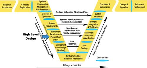
Where does the High Level Design take place in the project timeline? |
Is there a policy or standard that talks about High Level Design?
The FHWA Final Rule requires requirements to be developed for ITS projects funded with the Highway Trust Fund, including the Mass Transit Account. It also requires the analysis of alternative system configurations to meet requirements.
The IEEE 1233 Guide for developing system requirements specifications provides a standard for developing requirements.
Which activities are critical for the system’s owner to do?
How do I fit these activities to my project? [Tailoring]
The level of each activity should be appropriately scaled to the size and budget of the project. For example, a small project may have an analysis of alternatives that is only a page or two long, based upon qualitative comparisons. Constraining the number of sub-systems will also reduce the effort here and in the subsequent steps, such as integration and verification.
What should I track in this process step to reduce project risks, and get what is expected? [Metrics]
On the technical side:
On the project management side:
Checklist: Are all the bases covered?
| Were alternative project architectures/high level designs considered? | |
| Is there documented rationale for the selected project architecture/high level design? | |
| Are all interfaces identified and documented? | |
| Have industry standards been identified for the high level design? | |
| Is the design clearly documented? | |
| Is the high level design traceable to the system requirements? | |
| Do any of the requirements need to be changed based on the high level design development effort? | |
| Have the integration, verification, and deployment plans been updated in the SEMP? |
 Are there any other recommendations that can help?
Tools and techniques are available to support high level design. These tools include functional decomposition tools, modeling tools, and management tools for tracking changes to the high level design.
As a general rule, do not specify any part of the design unless that design decision has been justified during the alternatives studies. Sometimes, there is a tendency to insert design solutions to early in the process. For example, specifying workstation models, speed, memory to early may unduly constrain the implementation and lead to higher development costs or obsolescence before deployment of the system.
A closer look at high level design alternative project architectures and architectural views.
Sub-systems defined in the High Level Design
The High Level Design process defines the division of the system into sub-systems. Sub-systems, and the way they relate to each other, become the project architecture. Sub-systems may be needed for a the following reasons:
1] The development or procurement of system elements separately. For instance, if the system includes a wide area network [WAN] to connect multiple sites, that WAN may be a sub-system with a common interface [say the input to a router] to other sub-systems.
2] The deployment of system elements to different locations, or in different configurations, to multiple locations.
3] Dividing a complex system into simpler elements, each of which has an independent set of functions.
4] The allocation of functions to sub-systems. Sometimes it will be necessary to further decompose a function and allocate its sub-functions to individual sub-systems.
Hardware defined in the High Level Design
Hardware definition is somewhat synonymous with a physical architecture description [although there is also a software aspect to the architecture that will be covered next]. Each of the architecture components [which may or may not be considered sub-systems] must be defined in terms of its hardware. The definition may be generic [e.g. a workstation, a server, or traffic signal controller] or may be specific [by manufacturer and model number] depending on the results of the alternatives studies previously done.
Software defined in the High Level Design
Usually, each sub-system would have a separately identified software component. A sub-system may have several if it contains multiple processors. The software component should be defined both in terms of its custom developed parts [the application] as well as its COTS parts, such as the operating system, database software, or communications software. Here again, these software components should be defined generically, unless an alternative study has determined that a specific product is necessary. It is for the custom designed software application that tracing of functional and performance requirements are most important.
Other aspects of the high level software design may be dependent on the design methodology used. For instance, if object oriented methods are to be used, the high level design would identify major objects of the system.
Operator interface defined in the High Level Design
The details of the operator interface design are a critical part of the requirements of the system. It is also a part of the design that requires extensive input from the eventual users and operators of the system. Of course, if the operator interface is just an on/off switch, that is not much of a design problem. But, here we are talking about a workstation interface which can be surprisingly complex. The operator interface design must describe in detail everything displayed to the operator and all actions the operator can take, via the workstation. If the display contains a map, then all the contents of that map [e.g. roads, icons for loop detectors, signals, or message signs] must be defined both in terms of what it looks like, as well as when it is displayed. For instance, maps are generally divided into layers of similar information and each layer can be turned on or off by the operator. Similarly, all actions by the operator to enter data or to cause things to happen [like displaying a message on a sign] must be defined. Both display and entry should be designed in ways that limit operator error; from looking at the wrong data to entering a wrong value or command.
The project management and systems engineering team for the project must support decisions on the appropriate level of engineering and operational talent to be applied to the operator interface design. It is not a task to be left to the software programmers.
Alternative project level architectures
Based on the previous work [e.g., concept exploration, user needs, concept of operations, project plan, SEMP, and system requirements] this phase develops the project architecture of high level design of the planned system. The system requirements should be design independent. There is, usually, by this time in the project life cycle, some expectation of a functional and physical architecture brought forward from the concept exploration phase. The alternatives may be complete for the entire system or perhaps alternatives for just a part of the system. It is not uncommon that various alternatives can be combined into a large number of different configurations. Alternatives should be defined before the allocation is done. There may be alternative allocation of functions that should be considered. For example, loop data processing may be done at the roadside or centrally. Trade studies are used to evaluate the alternatives relative to the requirements and determine which are compliant. They will then compare the compliant alternatives in terms of cost, performance, and goals & objectives.
What to do with project architectures that fall short?
 Even project architectures that fall short of meeting all requirements may provide useful information. Sometimes an otherwise promising HLD may fall short of some of the requirements, especially ambitious performance requirements. If the HLD has some useful features then it may be carried forward as an alternate solution. Certainly the degree to which such a design does not meet user needs should be an important factor. Alternative fully-compliant designs should be documented for future reference. In fact, the entire evaluation process, including the alternatives considered and not considered, and the rationale for the selection and rejection, should be documented so stakeholders can review them.
There are many views that are very useful and should be used appropriately. The following are examples of different views that can be used. In the description at the beginning of this chapter, we focused on two views in the example, the functional view and the physical view. These are the most common ways that systems are described because they are easy to understand.
Operational view [behavioral, dynamic], describes how the system will react when it is stimulated. This is a dynamic modeling of the system that is important when real-time operation needs to be carefully analyzed.
Information views [data, data flow], are used in data intensive systems where the data needs to be modeled in order to determine how the optimum system architecture will handle the information. Examples:
Network views [distributed, centralized] are used when analyzing the interactions between various system elements on complex networks. This aids in understanding the addressing schema, and in analyzing protocol efficiencies for the network.
Activity view [functional], are the functions that are to be carried out by the system. [For examples, see the description at the beginning of this chapter.]
Physical view is the equipment that is used in the system. [For examples, see the description at the beginning of this chapter]


![Shows the flow for Phase [2] Task 2, High Level Design Process. Summaries are described for inputs, constraints, and enablers into the task; activities of the task; and outputs from the task. The flow is described in detail in the accompanying text.](/cadiv/segb/views/document/sections/Section3/26_files/image001.gif)