

Asphalt Binder Cracking Device to reduce Low Temperature Asphalt Pavement Cracking
APPENDIX D. ABCD USER'S MANUAL
- 15. ABCD Assembly Removal, Disassembly, and Cleaning after Test Completion
- 15.1 Allow cooling chamber to warm to room temperature for at least 30 minutes following completion of test. This is completed automatically since the standard temperature profile has one hour of warming to 25°C following the cooling period.
- 15.2 Assembly Removal from Chamber
- 15.2.1 Open cooling chamber door.
- 15.2.2 Carefully remove wires from ABCD rings.
- 15.2.3 Remove ABCD assemblies from cooling chamber.
- 15.3 Disassembly
- 15.3.1 Using thumb in bottom hole of silicone mold, push ABCD ring out of binder.
- 15.3.2 Carefully remove asphalt binder from mold.
- 15.3.3 Observe binder for crack at protrusion and quality of specimen.
- 15.4 Clean Molds
- 15.4.1 Wash silicone molds in soapy water with paper towel to remove asphalt stains.
- 15.4.2 Rinse molds in clean water.
- 15.4.3 Rinse again in another clean water bath.
- 15.4.4 Dry molds with towel or rag.
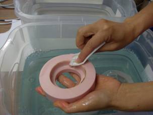
Step 15.4.1. Cleaning mold in soapy water with paper towel.
- 15.5 Clean ABCD Rings and Covers
- 15.5.1 Wipe all outside portions of ABCD ring and plastic covers with paper towel.
- 15.5.2 Use screwdriver to carefully remove binder from ABCD ring without notching the ring. Do not clean rings with water. Can use kerosene to remove binder stains from ring and covers. Kerosene may be necessary after about five tests.
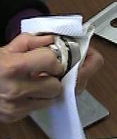
Step 15.5.1. Cleaning ring with paper towel.
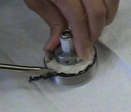
Step 15.5.2. Screwdriver to carefully remove binder from ABCD ring.
Appendix Interpretation of ABCD Data
Discussion of Figure A1
Figure A1 is the analyzed graph of ABCD data for the Nov. 4, 2008, ruggedness test of the EZ4 binder (PG64–34M SBS RTFO/PAV aged) at a cooling rate of 22°C/hr. What is the true cracking temperature of each specimen? Specimens M1 and M2 each have one large strain jump of 48.7 and 52.3 microstrains, so their cracking temperatures are easily identified by our Microsoft Excel analysis macro as –43.3°C and –43.0°C, respectively. However, specimens M3 and M4 each have two strain jumps of moderate magnitudes. Did specimen M3 crack at the higher temperature strain jump (M3a) or at the lower temperature strain jump (M3b)? The strain and temperature gages are located inside the ABCD ring and the ring is aligned with the pink mold such that the strain and temperature sensors line up with the protrusion. We believe the warmer jump (M3a) is caused by crack formation above the mold protrusion. Due to heat transfer, the chamber temperature may propagate downward through the binder, so the crack may be starting on the top of the protrusion and working its way downward resulting in a second strain jump at M3b at a lower temperature than M3a's crack.
Did specimen M4 crack at the higher temperature jump (M4a) or at the lower temperature jump (M4b)? The discussion is the same as for M3a versus M3b in the previous paragraph.
What is happening to specimen M1 at about –26°C to –30°C? This is an interaction between plastic cover and ring. The plastic cover has a higher thermal expansion coefficient than the Invar ring. The cover is connected to the ring through three small diameter (1/32" diameter x 5/16" long) pins. The contraction of the plastic cover pulls on the pins which likewise pull on the Invar ring causing the decrease in strain to –26°C. The pins then slip causing the ring to relax and the strain to increase. This phenomena is okay and does not affect the binder cracking temperature determination; however, the problem has been resolved by making the ring holes larger in more recent rings. The other three specimens did not exhibit this behavior because the pins were freer to slide in these rings.
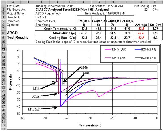
Figure A1. Analysis of binder EZ4 during ruggedness testing at 22°C/hr cooling rate.
Discussion of Figure A2
Figure A2 is the analyzed graph of ABCD data for the Nov. 20, 2008, ruggedness test of the EZ1 binder (PG64–16 AAM–1 RTFO/PAV aged) at a cooling rate of 20°C/hr. What is the true cracking temperature of each specimen? Specimens MB, MD, and MU each have one large strain jump of 43.3, 38.0, and 37.7 microstrains, so their cracking temperatures are easily identifiable by the analysis macro as –32.3°C, –29.5°C, and –30.9°C, respectively. However, specimen MG has two strain jumps of moderate magnitudes. Did specimen MG crack at the higher temperature jump (MGa) or at the lower temperature jump (MGb)? Unlike specimens M3 and M4 in Figure A1 where the two jumps were caused by vertical temperature propagation at the protrusion, here the mechanism is circumferential friction release between binder and ring. After the first strain release (MGa), the strain continues to drop. This is a sign that the binder was grabbing the ring by friction during cooling. Eventually (at about –28°C), the binder stopped grabbing the ring and slipped thus releasing strain. We believe this was not due to cracking. The binder then continued to cool and contract on the ring. Finally, the binder cracked at –31.1°C as indicated by the strain jump MGb.
If there are multiple strain jumps, in general the lower temperature jump indicates the binder cracking temperature. Higher temperature strain jumps are likely occurring due to friction release of the pins connecting the cover to the ring or friction release between the binder and ring, rather than binder cracking. However, the exception to this is Figure A1 where there are two strain jumps but the higher temperature jump is a crack above the protrusion that has not yet propagated below the protrusion.
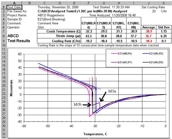
Figure A2. Analysis of binder EZ1 during ruggedness testing at 20°C/hr cooling rate.
Discussion of Figure A3
Figure A3 is the analyzed graph of ABCD data for a March 3, 2009, test of the AAA–1 binder at a cooling rate of 20°C/hr. What is the true cracking temperature of each specimen? Occasionally test results will look unruly like this with multiple strain jumps. The strain variation in specimen MoldX from –25°C to –34°C is due to the plastic cover/ring interaction as discussed above for Figure A2 specimen MG. A similar phenomenon is occurring for MoldO where the strain increases around –25°C. The plastic cover is contracting as the temperature drops. Due to the location of the pins connecting the plastic cover to the ring and the fact that the friction connecting each pin to the ring may be slightly different, there is expansion of the ring rather than contraction at the sensor location in the –25°C range. The ring may be contracting elsewhere along the circumference due to cover contraction, but the ring is expanding in the vicinity of the strain sensor.
The sudden jumps in MoldM strain are likely due to lubrication deficiency in the ring and mold preparation. If the rings are ever cleaned with acetone (possibly after 20 runs) to remove stains, it is important to put a very light coat of silicone grease on the ring (and wipe off thoroughly leaving only a very thin film. We use Dow Corning High Vacuum Grease silicone lubricant). Then brush the ring with glycerine/talc lubricant as described in the laboratory procedure above. Lack of lubrication causes the binder to adhere to the ring, then release from the ring, then re–adhere, until the binder finally cracks as indicated by the lowest temperature strain jump.
Though some of the cracking temperatures may be reliable for this data, it would be best to re–run the binder. A newer ring design has generally overcome this problem.
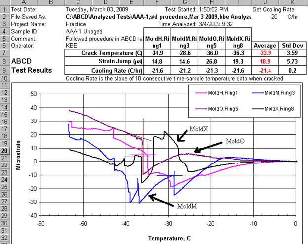
Figure A3. Analysis of binder AAA–1 during test at 20°C/hr cooling rate.
Discussion of Figure A4
The cracking temperatures are well–defined in this test. Specimen Sample 3 was not run so no data is present for it. Three samples are sufficient for reliable cracking temperature determination.
Sample 2 shows an increase in strain up to about –12°C due to the thermal contraction of the plastic cover being transmitted to the ring and strain sensor through three small pins. The strain increases to about –12°C for the same reason as in Figure A3 specimen MoldO.
Sample 4 shows similar behavior at the strain increases at –16°C and –20°C. Though these strain increases are more abrupt than the gradual Sample 2 increase, we believe it is the same phenomenon and not releasing of friction between ring and binder. Releasing of friction between ring and binder causes a very vertical strain jump.
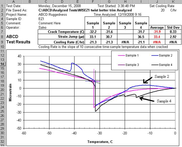
Figure A4. Analysis by Univ. of Wisconsin of binder EZ1 during test at 20°C/hr cooling rate.