PDF version of TechBrief (628 kb)
Introduction
This techbrief is a summary of the complete report FHWA-HRT-05-083, Wind Induced Vibration of Stay Cables.
Cable-stayed bridges have been firmly established as the most efficient and cost effective structural form in the 152-meter (m) to 472-m span range. With widespread popularity of cable-stayed bridges around the world, longer spans are being constructed employing increasingly longer stay cables. The stay cables are laterally flexible structural members with very low fundamental frequency and very little inherent damping. For this reason, the stay cables have been known to be susceptible to excitations, especially during construction, wind, and rain-wind conditions.
Recognition of this susceptibility of stay cables led to the use of some mitigation measures on several of the earlier structures. These included cable cross-ties that effectively reduce the free length of cables (increasing their frequency) and external dampers that increase cable damping. Perhaps due to the lack of widespread recognition of the stay cable issues by the engineering community and the supplier organizations, the application of these mitigation measures on early bridges appear to have been fairly sporadic. However, those bridges incorporating cable cross-ties or external dampers have generally performed well.
During the mid-1980s to mid-1990s a number of early cable-stayed bridges were observed exhibiting large stay oscillations under certain environmental conditions. From field observations it became evident that these vibrations were occurring under moderate rain combined with moderate wind conditions, and hence were referred to as rain-wind vibrations. The formation of a water rivulet along the upper side of the cable and its interaction with wind flow have been solidly established as the cause through many recent studies and wind tunnel tests. Exterior cable surface modifications that interfere with the formation of the water rivulets have been tried and proven to be very effective in the mitigation of the rain-wind vibrations.
At the time of the present investigation, it was evident that the rain-wind problem had been essentially solved at least for practical provisions for its mitigation. However, some further experimental and analytical work was needed to supplement the existing knowledge base on several other stay cable vibration issues in order to formulate adequate design guidelines.
Purpose
The objectives of this project were to:
- Identify gaps in current knowledge base.
- Conduct analytical and experimental research in critical areas.
- Study performance of existing cable-stayed bridges.
- Study current mitigation methods.
- Develop procedures for aerodynamic performance assessment.
- Develop design and retrofit guidelines for stay cable vibration mitigation.
Synthesis of Existing Information
An extensive literature survey was initially performed to form a baseline for the current study. An online database of references was created so that all members of the project team could add or extract information as necessary. The database includes the article titles, authors, reference information, and abstracts when attainable, and has built-in search capabilities.
An inventory of cable-stayed bridges primarily in the United States was created to organize and share existing records with the entire project team. This database includes information on geometry, cable properties, cable anchorages, aerodynamic detailing, site conditions, and observed responses to wind.
Analysis, Evaluation, and Testing
Mechanics of Wind-Induced Vibrations
There are a number of mechanisms that can possibly lead to vibrations of stay cables:
- Vortex excitation of an isolated cable or groups of cables.
- Rain-wind induced vibrations of cables.
- Wake galloping for groups of cables.
- Galloping of single cables inclined to the wind.
- Galloping of cables with ice accumulations.
- Aerodynamic excitation of overall bridge modes of vibration involving cable motion.
- Motions due to buffeting by wind turbulence.
- Motion due to fluctuating cable tensions.
Most types of wind-induced vibrations tend to be mitigated by increasing the Scruton number (Sc), given by:
m = mass of cable per unit length (kg/m)
 = damping as ratio of critical damping
 = air density (kilograms per meters cubed (kg/m3))
D = cable diameter (m)
This relationship shows that increasing the mass and damping of the cables increases the Scruton number and therefore reduces oscillation amplitudes.
From the information reported on the various types of cable vibrations due to wind loads, it was determined that galloping of dry inclined cables was the most critical issue requiring further experimental research.
Wind Tunnel Testing of Dry Inclined Cables
In order to clarify the dry cable galloping phenomenon and verify the instability criteria proposed by Saito, the project team conducted a series of wind tunnel tests of a full-size, 2-dimensional, sectional model of an inclined cable.1 The testing was performed in cooperation with the University of Ottawa in the propulsion wind tunnel at the Montreal Road campus of the Institute of Aerospace Research, National Research Council Canada (IAR/NRCC).
During the testing, limited-amplitude high-speed vortex shedding excitations were observed under a variety of conditions. While large oscillations of the cable occurred (double amplitudes up to a cable diameter), it is not conclusive that this was dry inclined cable galloping. It was more likely high-speed vortex shedding. Large vibrations were only found at the lowest damping ratios (<0.001). Above a damping ratio of 0.003, no significant vibrations were observed. Figure 1 shows the results of this experiment as compared to the instability line determined by Saito. The graph presents Reduced Wind Velocity Ur vs. the Scruton number, where:
UCRIT = critical wind velocity for instability
f = natural frequency
D = cable diameter
Figure 1: Comparison of wind velocity-damping relation of inclined dry cable.
The results of the wind tunnel testing have significant implications for the design criteria of cable-stayed bridges. The 2001 Post-Tensioning Institute (PTI) Guide Specification indicates that the level of damping required for each cable is controlled by the inclined galloping provision, which is more stringent than the provision to suppress rain-wind vibrations.2 This testing, however, suggests that if even a low amount of structural damping is provided to the cable system, inclined cable galloping vibrations are not significant. This damping corresponds to a Scruton number of 3, which is less than the minimum of 10 established for suppression of rain-wind vibrations. Therefore if enough damping is provided to mitigate rain-wind vibrations, then dry cable instability should also be suppressed.
Study of Mitigation Methods
Development of recommended design approaches was based on previous and current research focusing on cable aerodynamics, dampers, and cross-ties. Theories on the behavior of linear and nonlinear dampers and cross-tie systems were developed and compared to field measurements.
Linear and Nonlinear Dampers
Dampers are often attached to stay cables near the anchorages to suppress vibrations (figure 2). However, prior to the present study, criteria for damper design were not well established. The potential for widespread application of dampers necessitated a thorough understanding of the resulting dynamic system and a set of accepted design guidelines.
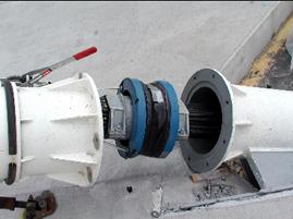
Figure 2: Damper at cable anchorage.
Analytical studies were performed covering both linear and nonlinear dampers. Design charts available for linear dampers were extended to cover nonlinear dampers. Results showed that while linear dampers may only achieve the optimal damping ratio in one mode of vibration, nonlinear dampers may attain optimal performance at different amplitudes of vibration in each mode. Therefore a nonlinear damper has potential design advantages over a wider range of modes than for a linear damper.
Results from field studies that are part of other ongoing projects were used to supplement the present study. Viscous dampers were installed on two stays on the main span of the Fred Hartman Bridge (La Port, TX), and data was collected for almost three years after the damper installation. The dampers were designed for optimal performance in the fundamental mode of vibration, which should provide adequate damping in the first several modes to suppress rain-wind vibration (i.e., approximately more than 0.5 percent). Results suggest that attached dampers render stay cables less susceptible to many types of excitation by increasing the low levels of inherent mechanical damping. Amplitudes were significantly reduced across all wind speeds observed in this study (up to 18 meters per second (m/s) at deck level).
Cross-Tie Systems
Another method to counteract undesired oscillations is to increase the inplane stiffness of stays by connecting them together with a set of transverse secondary cables, defined as cross-ties (figure 3). Cross-ties effectively reduce the free length of cables, therefore increasing their frequency. The connections transform individual cables into a more complex cable network.
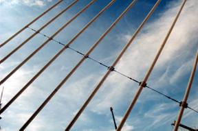
Figure 3: Cable cross-tie system.
The free-vibration analysis method was applied to the study of a cable network that was modeled after the Fred Hartman Bridge, which has a total of 192 cables in 4 inclined planes connected at 15 m intervals. A careful study of the solution patterns showed two categories of roots:
- Global modes, where the whole set of cables is involved in the oscillation.
- Local modes, where the maximum amplitudes are located in the intermediate segments of specific cables. The wavelength of these modes is essentially governed by the distance between two consecutive connectors.
This analysis shows that careful consideration of dynamic behavior of the system must be given for the design of cross-ties. The increase in frequency in the fundamental modes that is usually attained by adding cross-ties must be balanced with the potential undesirable behavior of the local modes. This aspect might potentially reduce the overall benefit of enhancing the performance of individual stay behavior by a network. For localized modes, however, the vibration is confined to a selected portion of the structure and the potential implications for long-term structural sensitivity (fatigue damage) are less relevant.
Cable Surface Treatment
The effectiveness of different surface modifications is determined from wind tunnel tests. No accepted methodology exists for the design of these elements. All major cable suppliers provide cable pipes that include surface modifications to mitigate rain-wind vibrations. Three types of cable surface treatments are shown in figure 4. Extensive research has been done in the past, and these surface treatments have been shown to be effective for mitigation of rain-wind vibration.
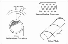
Figure 4: Types of cable surface treatments.
The double helix spiral bead formations are the most common on new bridges, such as the Leonard P. Zakim Bunker Hill Bridge (MA), General U.S. Grant Bridge (OH), Greenville Bridge (MS), William H. Natcher Bridge (KY), Simon-Keton Bridge (KY), and Bill Emerson Memorial Bridge (MO). As a manufacturer proprietary item, test data demonstrating their effectiveness is generally available from the cable suppliers.
Design Guidelines
New Cable-Stayed Bridges
General
A sufficiently detailed cable vibration analysis (including modal analysis of the cable system) must be performed as part of the bridge design to identify the potential for cable vibration. The following factors must be examined: the dynamic properties of the cables, dynamics of the structural system, geometry of the cable layout, cable spacing, exposure conditions, and estimated Scruton numbers (Sc).
Mitigation of Rain-Wind Mechanism
At a minimum, providing an effective surface treatment for cable pipes to mitigate rain-wind vibrations is highly recommended. One common method is the use of double-helical beads. The effectiveness of the surface treatment must be based on the tests applicable to the specific system, provided by the manufacturer.
Additional Mitigation
Depending on the outcome of the vibration study (Item 1), the provision of at least one of the following major vibration mitigation measures (in addition to surface treatment) is recommended:
- Additional damping (using external dampers).
- Cable cross-ties.
Minimum Scruton Number
Following are minimum desired Scruton numbers (Sc):
 for regular cable arrangements
 for cable pipes with effective surface treatment suppressing rain-wind vibrations (see note)
Note: Limited tests on cables with double helix surface treatments have suggested that m/D2>5 may be acceptable.3 It is felt, however, that such reductions should be made only for regularly spaced single cable arrangements. In general it is recommended to keep the Scruton number as high as possible by providing external dampers and/or cross-ties. For unusual geometry or double stay arrangements where parallel stays are placed within close proximity to one another, careful case-by-case evaluation of these limits are recommended.
External Dampers
Most dampers used in bridges are proprietary items, and design details should be provided by the manufacturer. Manufacturer warranties should be requested for all proprietary damping devices.
A damper can be tuned to yield optimal damping in any one selected mode of vibration. For other modes the level of damping will be less than this optimal value. Rain-wind vibrations occur predominantly in vibration mode 2. Therefore, if a damper is to be tuned to a particular mode to mitigate rain-wind vibrations, it appears logical to select mode 2.
There are many types and designs of dampers, and linear dampers have been shown to be effective through their widespread use in the past. However, recent analytical studies show that nonlinear dampers can be used to provide a more optimal condition than linear dampers, as these are effective over a larger range of modes. In particular, the damping performance of square-root dampers (b=0.5) is independent of the mode number and is only affected by the amplitude of vibration.
With some dampers (such as dashpot type), an initial static friction force must be overcome before engaging of the viscous element. Field experiments have shown the presence of this stick-move-stick-move behavior associated with such dampers. This may effectively provide a fixed node instead of the intended damping for the cable at low amplitude oscillations, and should be considered in design. The visco-elastic type dampers where an elastomeric element is permanently engaged between the cable and the supporting elements, theoretically, are free of such initial frictional thresholds. On the other hand, there are also damper designs that rely on friction as the energy dissipation mechanism and the static friction threshold for such dampers may be higher than for the other types.
Another factor needing consideration is the directionality of the damper. The cable vibrations observed in the field indicate both vertical and horizontal components of motion. Some damper designs are axi-symmetric and provide damping against cable motion in any direction. Other dampers (e.g. dashpot types) provide damping against motion only along the axis of the damper. It is possible to arrange two or more such dampers so that the combination is effective in all directions. As the majority of the observed motion due to rain-wind vibrations is in the vertical direction, it may be sufficient to provide damping against only the vertical motion. However, this has not been clearly established. It is recommended that damping be made effective against cable movement in any direction.
Damper mounting details may transfer lateral forces due to damper action onto components of the cable anchorage. Such forces must be considered in the design of the cable anchorages.
Cable Cross-Ties
If used, provide clear and mandatory specifications for cable cross-ties. Experience shows that cross-ties, when properly detailed and installed, can be an effective method for suppressing undesirable levels of cable vibrations. Reported failures of cross-ties have been generally traced to improper details and material selection.
The use of cross-ties creates local modes, which must be considered in design. The frequency of the first plateau of local modes should be kept as high as possible. Symmetric configurations of the restrainers with respect to intermediate-length cables is preferred to increase the frequency interval (lower limit in particular) corresponding to local modes, since they minimize the longest segment length.
Cable cross-ties must be provided with initial tension sufficient to prevent slack of the cross-ties during design wind events. The level of tension depends on the dynamic properties of the cable system and the design wind event. The initial cross-tie tensions must be established based on rational engineering analysis. Also, the tie to cable connection must be carefully designed and detailed for the transfer of the design forces.
User Tolerance Limits
A preliminary survey on sensitivity of bridge users to stay cable vibrations has indicated that the comfort criteria for cable displacement can be described using the following maximum single amplitudes (within 0.5 to 2.0 Hertz (Hz) range):
- 0.5 D (preferred).
- 1.0 D (recommended).
- 2.0 D (not to exceed).
While this aspect may need further study, the above can be used as a guide when such displacements can be computed and/or needed as input for design of such elements as dampers and cross-ties. The displacement limits need not be considered for extreme events.
Retrofit of Existing Bridges
If an existing bridge is found or suspected to exhibit episodes of excessive stay cable vibration, an initial field survey and inspection of the cable system should be performed to assemble the following information:
- Eye-witness accounts, video footage of episodes.
- Condition of the stay cable anchorages and related components, noting any visible damage and/or loose, displaced components.
A brief field instrumentation and measurement program can be used to obtain such parameters as the existing damping levels of the cables. Instrumentation of cables to record the vibration episodes, wind direction, wind velocity, and rain intensity during their occurrences could also provide some confirmation of the nature of cable vibrations.
The mitigation methods available for retrofit of existing bridges follow closely those provided for the new bridges. However, the application of surface treatment may be difficult, not practical, or cost prohibitive on existing structures. The addition of cross-ties and/or dampers is recommended.
A split-pipe with surface modifications can be installed over the existing cable pipe if this is found to be practical and cost effective. In many of the older bridges for cables using polyethylene (PE) pipes, ultraviolet (UV) protection to cable pipes is provided by wrapping the PE pipe with Tedlar® tape. These cables require periodic rewrapping as part of routine maintenance. The newer high-density polyethylene (HDPE) cable pipes are manufactured with a co-extruded outer shell that provides the needed UV resistance, thus providing a split-pipe as a secondary outer pipe has the added benefit of eliminating the need for future Tedlar taping for the UV protection.
In addition, any damaged cable anchorage hardware must be properly retrofitted or replaced. It is recommended that the original cable supplier be contacted to ensure the replacement of cable anchorage components and that the addition of mitigative devices are compatible with the original design of the stay anchorage area.
Recommendations for Future Research
The design guidelines provide a concise approach to suppress wind-induced vibrations in cable-stayed bridges and are based on the existing knowledge base and further investigations performed through this project. While the design recommendations are empirical, the mitigation methods discussed (dampers, cable cross-ties, and surface modification) are proven to be effective through both past field experience and laboratory testing. Future research in the following areas clarifying some of the remaining key issues would strengthen the design guidelines.
- Additional wind tunnel testing of dry inclined cables.
- Further study of deck-induced vibration of stay cables.
- Study mechanics of rain-wind induced vibrations.
- Develop a mechanics-based model for stay-cable vibration enabling the prediction of anticipated vibration characteristics.
- Predict the performance of stay cables after mitigation using the model.
- Perform a detailed quantitative assessment of various alternative mitigation strategies.
- Improved understanding of inherent damping in stays and damping provided by external devices.
- Improved understanding of cross-tie solutions.
- Refine recommendations for effective and economical design of stay-cable vibration mitigation strategies for future bridges.
This is the first time a set of design guidelines have been proposed for the mitigation of stay cable vibration. It is expected that future adjustments based on actual cable performance and advances in cable technology may require further refinements to the design guidelines.
References
- Saito, T., Matsumoto, M., and Kitazawa, M. “Rain-Wind Excitation of Cables on Cable- Stayed Higashi-Kobe Bridge and Cable Vibration Control”, Proceedings of Cable-Stayed and Suspension Bridges conference, Deauville, France, October, 1994.
- PTI Publication (2001). Recommendations for stay cable design, testing and installation. Post-Tensioning Institute Committee on Cable-Stayed Bridges, 4th ed.
- Larose, G.L., and Smitt, L.W. “Rain/wind induced vibrations of the parallel stay cables.” Proceedings of the 1999 International Association for Bridge and Structural Engineering (IABSE) Conference, Malmö, Sweden, 1999.
Additional Information
|
Researcher–This study was performed by HNTB Corporation in coordination with Johns Hopkins University, Rowan Williams Davies and Irwin, Inc., and Buckland and Taylor Ltd.
Distribution–This TechBrief is being distributed according to a standard distribution. Direct distribution is being made to the Divisions and Resource Centers.
Availability–This techbrief and the complete report FHWA-HRT-05-083 Wind Induced Vibration of Stay Cables will be available in summer 2007 and may be obtained from the FHWA Product Distribution Center by e-mail to report.center@fhwa.dot.gov, by fax to 301–577–1421, or by phone to 301–577–0818.
Key Words–cable-stayed bridge, cables, wind, rain, vibrations, dampers, cross-ties
Notice: This document is disseminated under the sponsorship of the U.S. Department of Transportation in the interest of information exchange. The U.S. Government assumes no liability for the use of the information contained in this document. This report does not constitute a standard, specification, or regulation. The U.S. Government does not endorse products or manufacturers. Trademarks or manufacturers' names appear in this report only because they are considered essential to the objective of the document.
Quality Assurance Statement: The Federal Highway Administration (FHWA) provides high-quality information to serve Government, industry, and the public in a manner that promotes public understanding. Standards and policies are used to ensure and maximize the quality, objectivity, utility, and integrity of its information. FHWA periodically reviews quality issues and adjusts its programs and processes to ensure continuous quality improvement. |
July 2007
FHWA-HRT-05-084
HRDI-07/08-05(WEB)E