U.S. Department of Transportation
Federal Highway Administration
1200 New Jersey Avenue, SE
Washington, DC 20590
202-366-4000
Federal Highway Administration Research and Technology
Coordinating, Developing, and Delivering Highway Transportation Innovations
 |
| This report is an archived publication and may contain dated technical, contact, and link information |
|
Publication Number: FHWA-HRT-06-138 Date: October 2006 |
Effects of Inlet Geometry on Hydraulic Performance of Box CulvertsCHAPTER 1. INTRODUCTIONThe South Dakota Department of Transportation (SDDOT) and the Federal Highway Administration (FHWA) collaborated on a research study conducted at the Turner-Fairbank Highway Research Center (TFHRC) hydraulics laboratory to determine the effects of a number of inlet geometry choices on culvert hydraulic efficiency. This study is a response to the large number of culverts that are installed in the United States and the fact that most of the current guidelines on culvert hydraulics are based on research completed more than 20 years ago. A conservative estimate indicates that there are more than 3.66 million linear meters (12 million linear feet) of culverts installed in the United States every year. The most widely recognized manual on culvert hydraulics is the FHWA Hydraulic Design Series No. 5 (HDS-5), Hydraulic Design of Highway Culverts,(1) published in 1985 but based on research conducted in the 1960s and 1970s. Most State DOT engineers use the FHWA HY-8 computer program (2) or similar programs based on HDS-5 for hydraulic evaluation and design of highway culverts. It is important to implement new technology in these programs to benefit practitioners in the State DOTs. Results from this study are presented in a format that is similar to HDS-5 to facilitate implementation in these programs. PROBLEM STATEMENTEach year, SDDOT designs and builds many cast-in-place (CIP) and precast box culvert structures that allow drainage to pass under roadways. The CIP boxes typically have 30-degree flared wingwalls and the precast have straight wingwalls with a 10.2-centimeter (cm) (4-inch) bevel on the inside edges of the wingwalls and top slab. An analysis of previous research, that research being described in South Dakota Culvert Inlet Design Coefficients,(3) conducted on a limited number of single barrel box culverts, indicated that further research was necessary to determine (1) the effects of multiple barrel structures, (2) loss coefficients of unsubmerged inlets, and (3) the effect of 30.5-cm (12-inch) corner fillets versus 15.2-cm (6-inch) corner fillets. In order to optimize the designs of both types of box culverts, the effects of the span-to-rise ratio, skewed end condition, and optimum edge condition should also be determined. A major problem with the current analysis programs for sizing box culvert structures (HY-8 and others) is that they do not analyze multiple barrel box culverts correctly. These programs model multiple barrel structures as though each barrel is a separate single box with its own wingwalls. Multiple barrel structures, however, share a single set of wingwalls. Most CIP box culverts fall in this category of multiple barrel structures with a single set of wingwalls. In the case of a wingwall configuration and a single barrel, the wingwalls conduct the flow directly into the barrel, reducing the contraction losses at the entrance. For the same configuration with multiple barrels, there is minimal contraction loss for interior barrels so losses are much lower. In other words, a multiple barrel system should perform better than the same number of single barrels. OBJECTIVESThe objectives of this study were to:
PROCEDURES AND FACILITIESAn SDDOT technical review panel worked with the FHWA research team to develop a test matrix that included six edge conditions and 32 inlet configurations for rectangular box culverts to be tested at two slopes, two tailwater conditions, and various discharge intensities. A total of approximately 680 tests were conducted in a special culvert test facility built for the study. A 1:12 model scale was selected for the test facility and very precise Plexiglas™ models were fabricated to isolate various features of inlet geometry. The inlet models were fabricated with clip-on components so that it was relatively easy to mix and match components to isolate any feature without switching whole models. The experimental setup included three subsystems: a culvert barrel, a headbox, and a tailbox. The headbox and tailbox had Plexiglas walls, which were supported by a metal frame. Figure 1 shows the headbox under construction. Figure 1. Photo. Culvert headbox under construction. 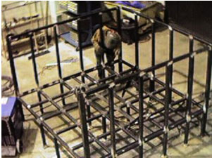 The headbox could be modified to vary the width of the approach flow. The height of the tailbox was adjustable to analyze different barrel slopes. The culvert barrel was made from a Plexiglas pipe. Ceramic class pressure sensors (pressure range: 0–10 kilopascal (kPa)(0–1.45 poundforce per square inch (lbf/inch2))) were mounted in the centerline on the bottom of the experimental setup (figure 2) to measure instantaneous hydraulic grade lines. Taking time averages led to more precise loss coefficient computations. The discharge was provided by a 0.140 cubic meter per second (m3/s) (5 cubic feet per second (ft3/s), computer controlled pump. Flow depths and mean velocities were computed from pressure sensor measurements in the culvert barrel where flow was parallel to the invert. In the highly turbulent region in the vicinity of the culvert inlet and in the headbox where the transverse flow distribution was extreme, particle image velocimetry (PIV) and/or velocity probes augmented these measurements. Figure 2. Diagram. Arrangement of the ceramic class pressure sensors.  PIV measures instantaneous velocity flow fields. It uses a focused light source, a high-resolution digital camera, and sophisticated computer logic to trace particle movements. The technique can accurately measure velocity in complex situations such as flows into culverts. |

