China Earthquake Reconnaissance Report: Performance of Transportation
Structures During the May 12, 2008, M7.9 Wenchuan Earthquake
OBSERVED DAMAGE TO BRIDGES
In this section, damage scenarios of bridge structures are reported. In addition to those inspected by the U.S. reconnaissance team, other significant bridges that were reported are discussed. The bridges inspected by the team are presented in order of visit, according to figure 3.
ZHIMA BRIDGE (31.1218 °N, 103.8500 °E)
Zhima Bridge is a six-span, T-girder river crossing structure on pier walls, with a span arrangement of 19.7 to 56.7 ft (6 to 17.3 m), shown in figure 9. It is mainly used by pedestrians and motorcycles. The approach on the highway side settled about 1.64 ft (0.5 m). No shear key or other structural damage was observed. Some guardrails may have been be displaced prior to the earthquake. Military personnel were welding steel railings, as shown in figure 10, when the reconnaissance team arrived at the bridge site.
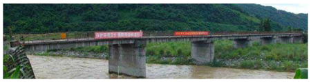
Figure 9. Photo. Overview of Zhima Bridge.
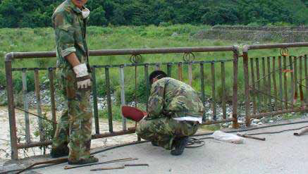
Figure 10. Photo. Welding on Bridge Railings.
As shown in figure 11, many buildings around the bridge suffered significant damage. There is a village on the other side of the bridge. Near the village were many tents that were most likely provided as shelters for people, as shown in figure 12.
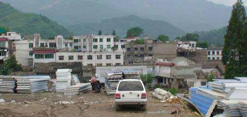
Figure 11. Photo. Building Damage Near Zhima Bridge.
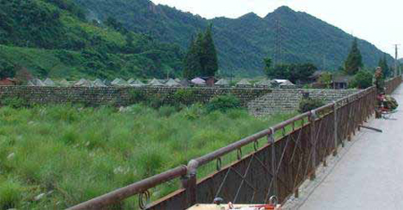
Figure 12. Photo. Tent Area Near the Bridge.
TONGJI BRIDGE (31.1585 °N, 103.8292 °E)
Tongji Bridge is a nine-span stone arch structure on reinforced concrete (RC) pier walls spanning a river, as shown in figure 13. Built in 1999, the bridge is located in the northwest of Chengdu Metropolitan Area and has a span arrangement of 29.5 to 110.5 ft (9 to 33.7 m). The abutment of the bridge on the river side was retrofitted to increase its strength against hydraulic forces, as indicated in figure 13. During previous floods, water rose to the arch level. It was observed that water leaked through the first arch from the bridge deck due to rains. Minor pounding damage at railing joints and approach settlement were observed, as illustrated in figure 14.
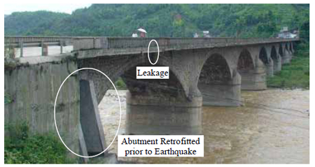
Figure 13. Photo. Overview of Tongji Bridge.
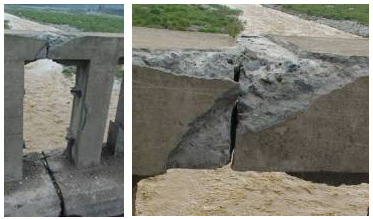
Figure 14. Photo. Pounding Damage at Railing Joints.
XIAOYUDONG BRIDGE (31.1859 °N, 103.7677 °E)
Xiaoyudong (little fish hole) Bridge is a four-span RC arch structure with long approaches supported on two abutments and three intermediate bents, as shown in figure 15 and figure 16. Each bent consists of one cap beam and two rectangular columns and is supported on two drilled shaft foundations of 6.56 ft (2 m) in diameter. Built in 1999, the bridge is oriented east-west. Each span is 131.2 ft (40 m) long and is an arch strengthened with two struts. The arch and strut are both supported on the pile cap of drilled shafts. The bridge deck is integrally cast with the top of the strut and arch but is seated at the bent caps and abutments. Expansion joints exist at each abutment and bent.
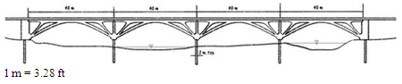
Figure 15. Illustration. Schematic Elevation View of Xiaoyudong Bridge.
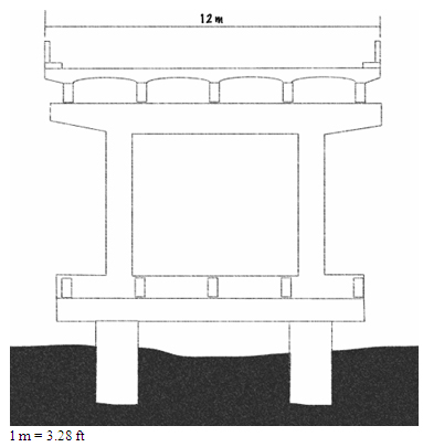
Figure 16. Illustration. Typical Cross Section at Pier of Xiaoyudong Bridge.
The two spans on the west side of the bridge had collapsed, and the eastern most span was severely damaged, as shown in figure 17. The remaining span suffered little damage. As shown in figure 17, bent 2 is located in the middle of the river, with the longest pile shafts exposed above ground. Bent 2 was significantly tilted while the other intermediate bents appeared to have little rotation. The difference in the stiffness of the various bents most likely contributed to the collapse of the two western spans. Under severe shaking around the bridge site, as indicated by landslides shown in figure 18, bent 2 rotated, resulting in unseating of the two spans. The bent cap was approximately 33.15 inches (850 mm) across, and the seat length of each girder was approximately 11.7 inches (300 mm), which is very limited for strong shaking at the bridge site.
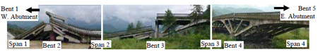
Figure 17. Photo. Overall View of the Remaining Arches.
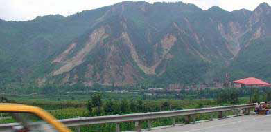
Figure 18. Photo. Significant Landslides Near the Bridge.
The reconnaissance team did not find any obvious evidence of lateral spreading or liquefaction at the bridge site. However, it is highly possible that under strong shaking, lateral spreading or liquefaction could have occurred in the middle of the river on the west side of the bridge. In that case, the tilting of bent 2 could be easily explained.
The easternmost span also suffered significant damage. As shown in figure 19, shear failures were observed on the top end of the struts and on the bottom end of the arches. The shear key on the east abutment was damaged. The shear failure is shown in figure 20. At the top end, each strut seemed to be reinforced with 15 #25 (metric) bars. Some of them were fractured.
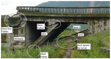
Figure 19. Photo. Damage in Easternmost Span.
Source: Dr. Zhenming Wang, Kentucky Geological Survey, University of Kentucky
Figure 20. Photo. Details of Shear Failures in Easternmost Span.
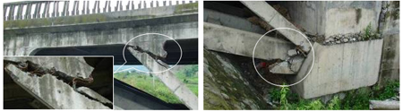
The damage to the easternmost span was likely caused by the surface fault near the east abutment, as shown in figure 7. Figure 21 presents a schematic of the interaction between the fault rupture and the east abutment of the bridge. When the hanging wall of the thrust fault moved up and right, relative to the foot wall supporting the east abutment, the levee began to bear on the arches and added significant shear forces and bending moments, especially at the east ends of the arches. Designed for axial forces, the arches failed in shear at their east ends. The top end of the arches remained intact due mainly to its larger section. Due to the shear failure in the arches, the east span deflected downward significantly, as shown in figure 19, and added more loads to the strut, resulting in its shear failure as well. At the same time, span 4 pushed toward bent 4 and caused flexural cracks at the pile shaft, as indicated in figure 22.
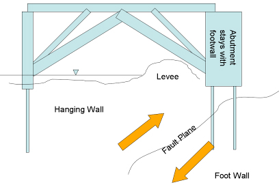
Figure 21. Illustration. Surface Fault Movement and Interaction with Bridge.
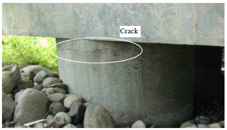
Figure 22. Photo. Flexural Crack on Pile Shaft at Bent 4.
Span 3 suffered little damage. In addition to the flexural crack on the pile shaft at bent 4, the bridge deck cracked near the location where the arch element was connected to the bridge deck on the east side of the span, as shown in figure 23. At midspan and at the west side of span 3, there was no cracking. Therefore, the damage was most likely caused by a significant horizontal earthquake force in the west direction. In this case, the bending moment in the bridge deck exceeded its capacity at the crack location.
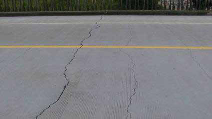
Figure 23. Photo. Transverse Crack on Top of the Bridge Deck in Span 3.
ANZHOU BRIDGE (31.6315 °N, 104.4388 °E)
Anzhou Bridge, built in 1996, is a two-arch structure along Highway S105. Each arch is 262.4 ft (80 m) long, as shown in figure 24. A slab superstructure is hung from the two RC vertical arches using a number of cable suspenders, as shown in figure 25. Surprisingly, there is no cross bracing between the arches above the deck, which may explain why the cross bracing below the deck had cracks, as shown in figure 26. The cross bracing members are designed to restrain the arches from transverse movement. The concrete deck spalled around the cable suspenders, around the arches, and at the expansion joints, as shown in figure 27. The spalls and cracks suggest that the slab superstructure was shaken transversely and longitudinally during the earthquake.
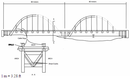
Figure 24. Illustration. Schematic of Anzhou Bridge.
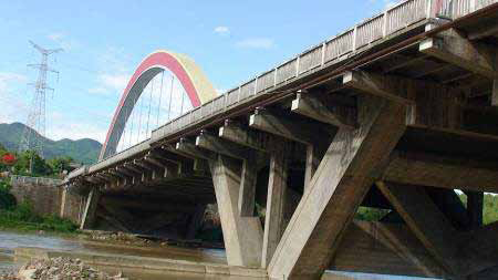
Figure 25. Photo. Part of the Anzhou Bridge.
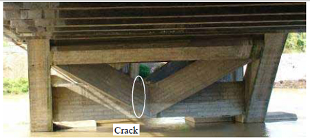
Figure 26. Photo. Cracks on Diagonal Members/Transverse Bracings.
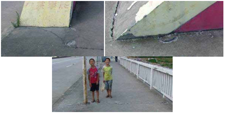
Figure 27. Photo. Damage in Bridge Deck Around Arch and Suspender.
Although the damage was relatively minor, traffic was restricted to the middle of the deck, as shown in figure 28, as a precautionary measure. An attempt was made to build a roadway with embankment materials and pipe culverts to serve as a detour over the river, as shown in figure 29. However, it appeared that the building of the detour was abandoned because the river flow was too strong and the roadway was rapidly washed away.
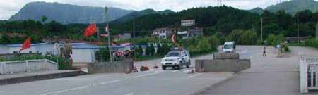
Figure 28. Photo. Road Block on Highway.
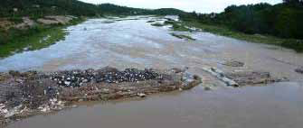
Figure 29. Photo. Temporary Roadway over the River.
BAIMAYAN BRIDGE (31.6666 °N, 104.4278 °E)
Baimayan Bridge is a six-span skewed slab bridge with a 68.88-ft (21-m) span length and carries north-south traffic along Highway S105. It was constructed in 2003. As shown in figure 30, the bridge is supported on three-column bents. During the earthquake, the bridge suffered minor damage. Concrete spalling was observed at the embankments, and shear keys were damaged, as shown in figure 31. Both indicated that the bridge was shaken during the earthquake. The expansion joints were offset by approximately 2.73 inches (70 mm) in the traffic direction and 1.56 inches (40 mm) in the transverse direction (see figure 32). The level of shaking at the bridge site is notable. In a nearby town, buildings were severely damaged, as shown in figure 33.
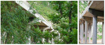
Figure 30. Photo. Overview of Baimayan Bridge.
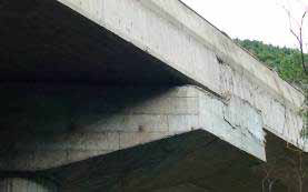
Figure 31. Photo. Damage in Shear Key.
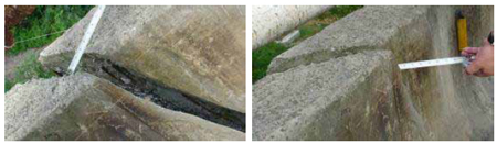
Figure 32. Photo. Measurement of Expansion Joint Offset.
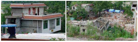
Figure 33. Photo. Building Damage in Nearby Town.
BAIYUN BRIDGE (31.4536 °N, 104.7172 °E)
Baiyun Bridge was built in 2001 and spans the Anchuang River in the northwest-southeast direction. It is a three-span simply supported tied-arch structure, as shown in figure 34. As illustrated in figure 35, the three spans of the bridge are 223, 262.4, and 223 ft (68, 80, and 68 m). The height-to-span ratio is approximately 1:5. The arches are supported on four-column bents and seat-type abutments. To protect ties from corrosion, the tendon duct of each tie was filled with oil. Both the tie and the oil duct were embedded in the RC bridge deck. After the earthquake, oil in the tendon ducts began to leak, as shown in figure 36, suggesting that the ducts developed cracks during the earthquake or that the anchorages were damaged. In addition, concrete spalling and cracking were observed on the bridge deck around the arches and cables, as shown in figure 37.
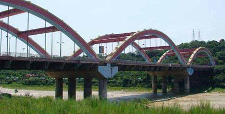
Figure 34. Photo. Overview of Baiyun Bridge.
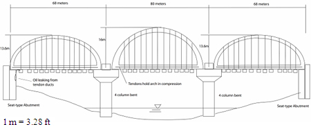
Figure 35. Illustration. Schematic of Baiyun Bridge.
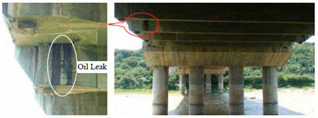
Figure 36. Photo. Oil Leakage Underneath the Bridge Deck.
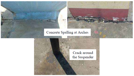
Figure 37. Photo. Concrete Spalling and Cracks on Bridge Deck.
NANHE BRIDGE (31.4486 °N, 104.7522 °E)
Built in 1989, Nanhe Bridge is a five-span open-spandrel arch structure with an additional slab bridge at the north end, as shown in figure 38. The bridge is oriented north-south. Six secondary arches (haunch soffit) are supported by the spandrel columns on each of the five main arches. As shown in figure 39, transverse cracks were observed at the crown of all secondary arches. The cracks covered the entire width of the secondary arches but did not penetrate the deck thickness. The damage pattern indicated that two adjacent secondary arches and their common supporting column may have rotated slightly during the earthquake.
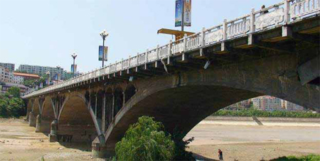
Figure 38. Photo. Overview of Nanhe Bridge.
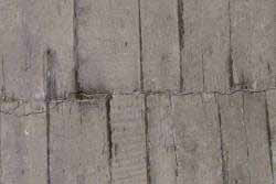
Figure 39. Photo. Transverse Crack at the Crown of Secondary Arch.
MIANYANG AIRPORT VIADUCT (31.4285 °N, 104.7472 °E)
Mianyang Airport Viaduct is a U-shaped structure illustrated in figure 40. Built in 2001, the middle of the structure is a double deck system serving airport passengers. Two approaches (northwest and southeast) are connected to the upper level of the airport. They are supported on two-column bents, as shown in figure 41.
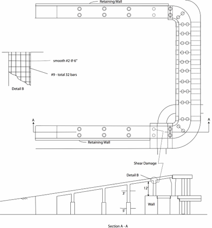
Figure 40. Illustration. Schematic of the Mianyang Airport Viaduct.
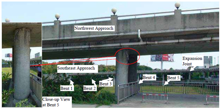
Figure 41. Photo. Overview of the Viaduct Structure.
The southeast approach consists of a five-span structure supported on columns of varying heights. The five-span structure is continuous, with expansion joints at both ends. The diameter of the upper portion of the columns (approximately 3.28 ft (1.0 m)) is smaller than that of the lower portion (approximately 4.92 ft (1.5 m)). The columns have a smooth #5 (metric) spiral spaced at 5.85 inches (150 mm) and 32 #29 (metric) bars for longitudinal reinforcement. The northwest approach also has five spans. The spans are similar to those on the southeast approach except that the lower portions of the tallest circular columns at bent 5 are connected by a concrete wall, as shown in figure 41. The concrete wall makes bent 5 much stiffer than its adjacent bents.
The two short, stiff columns at bent 5 of the northwest approach had severe shear cracks that exposed the aggregate and reinforcement as well as minor diagonal shear cracks, as shown in figure 42 and figure 43. The damage probably resulted from large gravels used in the concrete mix (approximately 3.9 inches (100 mm), illustrated in figure 42) and loose tie bars, as well as from the relatively rigid wall effect, which lead to irregular stiffness distributions. Torsion resulting from the asymmetry in stiffness of the structure probably caused the different levels of shear damage in the two columns at bent 5. In the vicinity of bent 5, the retaining wall underneath the northwest approach had a diagonal crack, as shown in figure 44. In addition, there was spalling of the superstructure concrete at the expansion joint next to bent 5. The southeast approach structure had minor flexural cracks at the lower portion of the columns at bent 4.
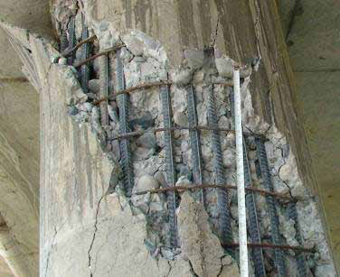
Figure 42. Photo. Shear Failure at West Column of Bent 5 of the Northwest Approach.
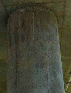
Figure 43. Photo. Shear Crack at East Column of Bent 5 of the Northwest Approach.
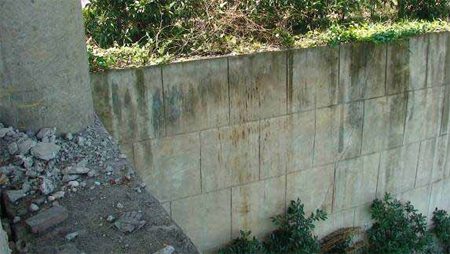
Figure 44. Photo. Crack on Retaining Wall Underneath the Northwest Approach.
BRIDGES IN NANBA TOWN (32.2080 °N, 104.8289 °E)
Three bridges cross a river near Nanba Town, as shown in figure 45. The west structure was a concrete and masonry three-span arch bridge built in the 1970s. The old arch bridge completely collapsed during the earthquake, as shown in figure 46. Immediately downstream of the arch bridge was a 10-span river crossing (on a 10-degree skew) that was under construction during the earthquake, as shown in figure 47. Each 19.68-ft (6-m)-long span was simply supported on two-column bents and seat-type abutments with 21.84-inch (560-mm) seats. As shown in figure 48, each span consisted of eight precast box girders with a cross section of 41.61 inches (1,067 mm) by 59.28 inches (1,520 mm). Each girder was supported on two 7.8 inch (200-mm) round elastomeric bearings at each end. The girders were in place, but the concrete deck had not yet been poured at the time of the earthquake, as seen in figure 48.
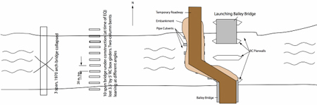
Figure 45. Illustration. Three Bridges at Nanba Town.
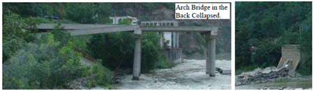
Figure 46. Photo. Collapse of the Old Three-Arch Bridge.
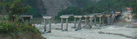
Figure 47. Photo. Damage Scenario of 10-Span Bridge Under Construction
During the Earthquake.
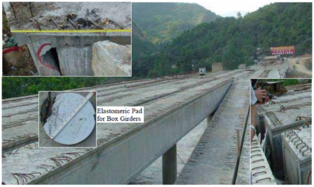
Figure 48. Photo. Damage to the 10-Span Bridge Under Construction.
As shown in figure 47 and figure 48, most of the box girders of the new bridge dropped into the river, and the two-column bents were distorted. The end box girders were transversely displaced by approximately 29.64 inches (760 mm). The deck had not been poured, there were no real transverse bracing or shear keys, and girders were on a slight skew, all of which contributed to the damage. Also, many of the bents were leaning or distorted, but no damage was visible above the water line.
There was no indication that the 10-span bridge suffered any damage due to a fault crossing. As such, the three-span arch bridge must have been damaged by ground shaking, perhaps exacerbated by soil movement. Liquefaction, lateral spreading, or other soil movement also may have been responsible for the distortion of the two-column bents. The reconnaissance team was not able to discern what type of foundation system the bents were supported on, but apparently they were not sufficiently embedded in good material.
On the east side of the old and new bridges was a temporary structure that was being constructed by launching Bailey bridges onto new RC pier walls. As shown in figure 49, vehicles were crossing the river on fill material laid over culverts during construction. Figure 50 shows the completed Bailey bridge.
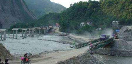
Figure 49. Photo. Overview of Temporary Bridge Construction.
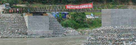
Figure 50. Photo. Bailey Bridge in Place.
MIAOZHIPING BRIDGE (31.0184 °N, 103.5491 °E)
Miaozhiping Highway from Dujiangyan to Wenchuan was under construction during the earthquake. It consists of a tunnel at Zhipingpu and a bridge over the Ming River, as shown in figure 51 and figure 52. The tunnel, shown in figure 53, experienced little damage during the earthquake. The highway was scheduled to open in October 2008. Near the highway is the Dujiangyan Dam. The bridge of approximately 0.87 mi (1.4 km) consists of three parts: a main span and two approach spans, as shown in figure 54.
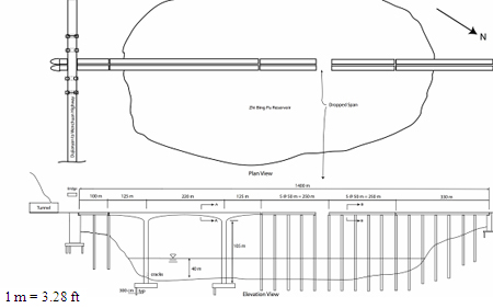
Figure 51. Illustration. Plan and Elevation View of Miaozhiping Bridge.
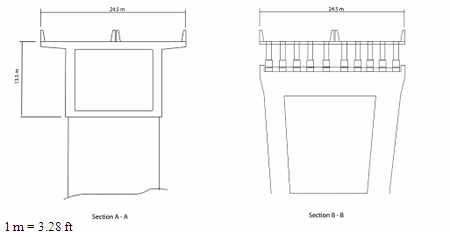
Figure 52. Illustration. Cross Section of Main Span and Approach Bridge
for Miaozhiping Bridge.
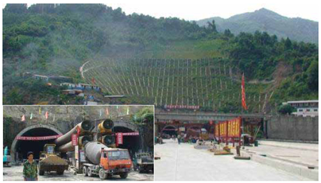
Figure 53. Photo. Miaozhiping Tunnel.
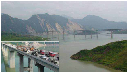
Figure 54. Photo. Overview of Miaozhiping Bridge.
As shown in figure 55, the approach near the tunnel is a two-span, RC girder structure with a 164 ft (50-m) span length. The bridge deck is supported on five RC girders and two-column bents with several cross struts. The bridge deck is continuous, but the girders are simply supported on the bents. As shown in figure 51 and figure 54, the main bridge is a continuous, non-prismatic, three-span structure supported on two intermediate wall piers with span lengths of 410, 722, and 410 ft (125, 220, and 125 m). The superstructure is a single-cell box girder structure. The depth of girders varies to a maximum depth of 13.1 to 14.8 ft (4.0 to 4.5 m).
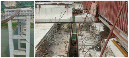
Figure 55. Photo. Drop-Off Span and Construction Details Between Two Spans.
The approach bridge on the other side of the main span has three parts of 820, 820, and 328 ft (250, 250, and 100 m). Each of the first three parts has five spans of 164 ft (50 m), supporting ten RC girders. All of the girders are simply supported on the bents for dead load, but the bridge deck is continuous for live load. The bents are as tall as 344.4 ft (105 m). In some locations in the main span of the bridge, the bents are 131.2 ft (40 m) deep into water in the Zidingdu reservoir of the Dujiangyan Dam. Expansion joints are used between the parts and between the approach and main bridge.
The construction of the bridge was near completion at the time of the earthquake, with only the installation of expansion joints remaining. The most severe damage was to the end span of a five-span T girder segment that became unseated at the expansion joint end, fractured in the continuous deck at the other end due to gravity load, and fell off the supporting bent caps. The bent seats were approximately 11.7 inches (300 mm) long, but the bridge experienced at least 19.5 inches (500 mm) of longitudinal movement due to earthquake shaking. Since the columns of each bent are approximately 344.4 ft (105 m) tall, the accumulated displacement at the bent cap was probably significant during the earthquake. There were other indications of large longitudinal movement. As shown in figure 56, the barrier rails overlapped by about 11.7 inches (300 mm) at the southeast expansion joint. The barrier also displaced transversely by approximately 9.75 inches (250 mm). Divers found cracks at the bottom of the main span columns due to earthquake shaking. Shear key failure was also observed, as shown in figure 57. After the earthquake, the bridge deck was put back into place with hydraulic jacks.
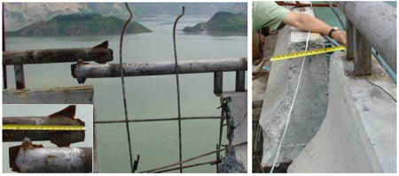
Figure 56. Photo. Longitudinal and Transverse Offset of Bridge Deck.
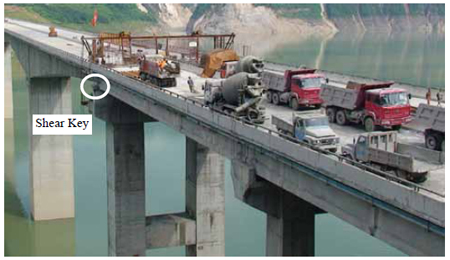
Figure 57. Photo. Shear Key Failure.
The end of Miaozhiping Bridge near the tunnel is divided into two parallel elevated structures to guide traffic in two directions through the twin tunnels, as shown in figure 58. Over the southeast approach is a four-span RC girder bridge built in 2004. The bridge supports the old highway from Dujiangyan to Wenchuan and Juzhaigou. The old highway was built along the mountain terrain perpendicular to the Zhipingpu Highway at Zhipingpu Town. The bridge showed shear key failures and embankment cracking (see figure 59).
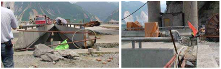
Figure 58. Photo. End of Miaozhiping Bridge and its Overpass for the Old Highway.
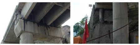
Figure 59. Photo. Damage to Shear Key and Embankment of the Overpass.
There are several RC girder bridges in the vicinity of Miaozhiping Bridge, as shown in figure 60. These bridges appeared to suffer little damage. No weight limits were posted on these bridges.
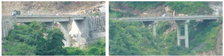
Figure 60. Photo. Bridges in the Vicinity of Miaozhiping Bridge.
MINGJIANG BRIDGE AT YINGXIU (30.989 °N, 103.329 °E)
Mingjiang Bridge at Yingxiu is located about 1,640 ft (500 m) north of the fault. The bridge was built in 2007 and is a T-girder structure with two-column bents that are supported on pile shafts. It has a span arrangement of 13.12–82 ft + 3.28–88.56 ft (4–25 m + 1–27 m), as shown in figure 61 and figure 62. It had some damage due to a landslide at the east span. As a result, the Sichuan Province Government built a Bailey bridge over the east span to carry vehicles over the damage. There were several other structures that were damaged in the same vicinity, including an elevated viaduct, a tunnel, and a levee, as shown in figure 62.
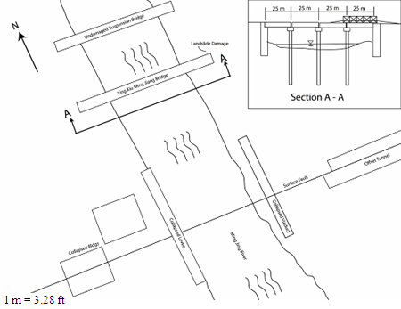
Figure 61. Illustration. Schematic of Mingjiang Bridge at Yingxiu.
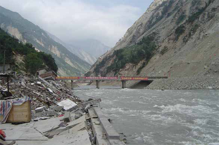
Figure 62. Photo. Mingjiang Bridge and Other Structural Damage in Yingxiu Village.
BAIHUA BRIDGE (31.0443 °N, 103.4749 °E)
Baihua Bridge is part of a Class 2 Highway from Dujiangyan to Wenchuan. It was built in 2004 by the owner of a nearby hydroelectric plant. As shown in figure 63, the bridge is an 18-span, RC structure with a total length of 1,476 ft (450 m). The superstructure is supported on two-column bents of varying heights as it climbs over the hilly terrain. The tallest bents have one or two struts to provide transverse restraint between the columns. The bridge has both straight and curved spans. For convenience, the bridge structure can be divided into six sections, as summarized in table 2. The superstructure is a prestressed box girder with a drop-in T-girder span between bent 9 and bent 10. There are expansion joints at bents 2, 6, 9, 10, and 14 and at the two seat-type abutments. For the drop-in span, the bridge deck rests on the bent cap at both ends.
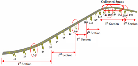
Figure 63. Illustration. Schematic of Baihua Bridge Before the Earthquake.
Table 2. Parameters of Baihua Bridge.
Section |
No. of Span |
Span Length (m) |
Section Length (m) |
1 |
5 |
25 |
125 |
2 |
4 |
25 |
100 |
3 |
1 |
50 |
50 |
4 |
3 |
25 |
75 |
5 |
5 |
20 |
100 |
6 |
2 |
25 |
50 |
1 m = 3.28 ft
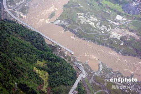
During the earthquake, one curved section of the bridge completely collapsed, as shown in
figure 64. The rest of the bridge suffered varying degrees of damage, including shear cracks and failure at columns and struts, shear key failure, and bearing failure as shown in figure 65 through figure 69 for bents 3, 9, 15, and 18. At bent 3, typical damage occurred between the strut and columns in the form of spalling and cracks. At bent 9, with expansion joints, the superstructure had significant transverse displacement, knocking off the shear key. At bent 15, the bridge section was completely collapsed, probably due to the shear and flexural failure of the columns. At bent 18, significant spalling occurred underneath the bridge deck in addition to cracks between the columns and the strut.
Source: www.cnsphoto.com
Figure 64. Photo. Postearthquake Damage.
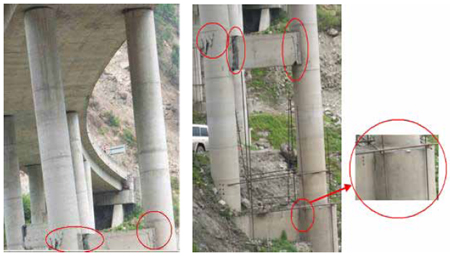
Figure 65. Photo. Damage at Bent 3.
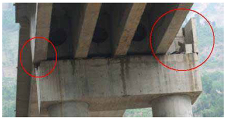
Figure 66. Photo. Damage at Bent 9.
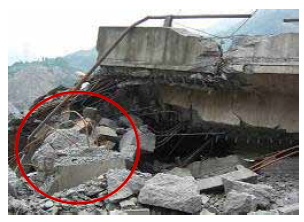
Figure 67. Photo. Column Shear and Flexural Failure at Bent 15.
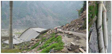
Figure 68. Photo. Column Shear Failure and Section 5 Collapse at Bent 15.
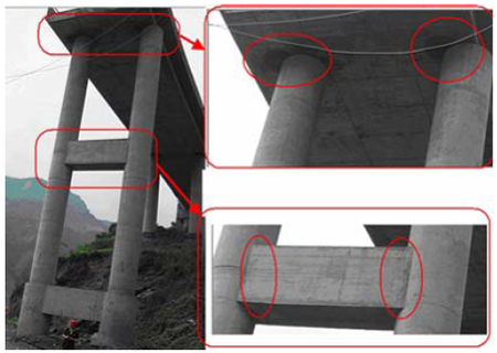
Figure 69. Photo. Damage at Bent 18.
The curved part of the bridge was probably subjected to higher deformation and stress during the earthquake, resulting in collapse. Due to the tall columns, the earthquake caused tilting that pushed the superstructure almost off its support at several locations in the straight part of the bridge. A detour was graded along the side of the damaged bridge. Considering the high risk of further collapse during an aftershock, the bridge was demolished with dynamite, as shown in figure 70 and figure 71.
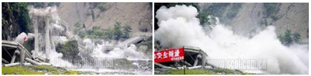
Source: www.scol.com.cn
Figure 70. Photo. Blast Demolition of Baihua Bridge.
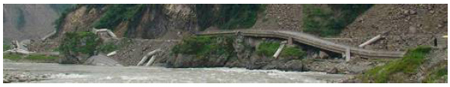
Figure 71. Photo. After Demolition of Baihua Bridge.
Similar to Xiaoyudong Bridge, this bridge could have been damaged by surface faulting, though the reconnaissance team did not find a clear surface fault feature near the bridge site. Considering the complex vibration system of the irregular structure with varying column heights and a lack of continuity between the substructure and superstructure, severe shaking alone could have resulted in the collapse. Still, the bridge is very close to the fault and several photos taken immediately after the earthquake show what looks to be a surface fault under the bridge. During the field reconnaissance nearly three months later, all signs of the fault were gone, and the bridge was lying on the ground.
ZHIMA BRIDGE (31.0308 °N, 103.4675 °E)
Zhima Bridge has four spans of 65.6 ft (20 m) and is an RC T-girder structure, as shown in figure 72. It is supported on very tall RC two-column towers. The bridge is a river crossing link across the deep canyon shown in figure 73. The bridge suffered significant movement both longitudinally and transversely. Most shear keys were damaged, as shown in figure 73. As a result, a long Bailey bridge was launched over the existing superstructure to support traffic. It appeared that the north span may have almost dropped.
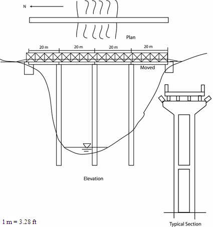
Figure 72. Illustration. Schematic of Zhima Bridge.
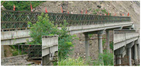
Figure 73. Photo. Bailey Bridge Over the Existing, Damaged Bridge.
SHOUJIANG BRIDGE (30.9790 °N, 103.4599 °E)
Shoujiang Bridge is an eight-span, 918.4-ft (280-m)-long, T-girder superstructure supported on very tall two-column towers and pier walls, as shown in figure 74. The tallest piers were approximately 196.8 ft (60 m) high, the approach spans were 98.4 ft (30 m) long, and the four main spans were 131.2 ft (40 m) long. Both the towers and the pier walls were supported on pile foundations.
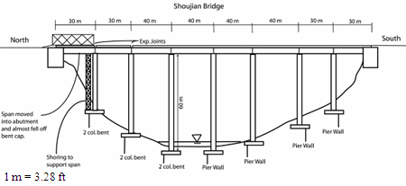
Figure 74. Illustration. Schematic of Shoujiang Bridge.
As shown in figure 75, the north span almost fell off the north tower and was supported on a steel tower with a Bailey bridge over the last span to carry traffic. The north approach embankment showed evidence of ground failure and movement. The west side showed evidence of ground failure, but the east side looked stable. There was a shear failure of the north abutment.
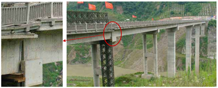
Figure 75. Photo. Overview of the Bridge Structure and Damage Location.
The entire structure shifted north and then back, leaving the girders of the first span pushed onto the approach and almost unseated from the first two-column tower. Damage was the result of ground shaking and insufficient seat to accommodate the resulting movement.
|


