

Archived: Interstate Technical Group on Abandoned Underground Mines
Third Biennial Workshop
Mine Subsidence Stabilization In Steeply Dipping Seams In the Canadian Rockies: A Project Overview
Presented by
Patrick E. Gallagher1
Abstract
CTL Engineering has been working on a project located in the Bituminous Coalfields of western Canada near the world famous Banff National Park. A large commercial/residential development has begun on a 5000-acre tract of land where a multiple seam abandoned coal mine is present. The coal was extensively mined from the mid-1800's until 1974 in four separate seams, all of which are steeply dipping (up to 85°). The workings pose a serious subsidence threat to the future buildings to be constructed in the development. Our mine Stabilization program was designed to establish priority areas for Stabilization and develop grout mixes that could overcome the steep dip of the seams.
The presentation of a paper at this conference will cover topics such as prioritization of the site, explorations of the proposed Stabilization areas, evaluation criteria for the grouting patterns, mix designs, and borehole photography of the underground pumping operations. Other discussion includes the regulatory review of the grouting and the process of permitting an underground injection program.
Project Description
The project is located 60 miles (100 km) due west of the City of Calgary, Alberta, Canada in the town of Canmore. The area surrounding the site is world renowned for its natural scenic beauty and popular travel destination of more than two million people annually. The land owners are presently planning to develop nearly 1900 acres (759 hectares) with residential, resort, and commercial communities. The entire property is underlain with abandoned underground coal mines in four separate seams. The mining method was room and pillar with some second mining encountered sporadically throughout the property. The geology is extremely complicated with folded, faulted, and steeply inclined sedimentary deposits consisting of interbedded sandstone, shales, coals and limestones.
Fortunately, the past mine workings were well documented with extensive surveys and very detailed maps. The techniques employed by the miners to overcome near vertical dip angles are very impressive including hand augering, blasting and shoveling the coal on ladders that were laid on the mine floor for some 2,500 feet (762 m). The seam thickness' varied from 6 to 9 feet (1.83 to 2.74 m) typically with a limestone roof and the overburden consisted of a soil horizon averaging 20 feet (6.1 m) and a maximum depth to mine level of 900 feet (274 m). Dip angles varied from 25° to 85° and the mine floor was a weathered clayshale.
Risk Assessment and Regulatory Review
The first phase of the proposed development included 375 residential home sites and all of the infrastructure to support the construction of the homes. Utilities, roadways, wildlife crossings and various right-of-ways had to be included in our assessment of Stabilization priorities in addition to the residential structures. The risk assessment evaluated the following criteria:
- Depth of mine workings
- Void height
- Proposed land use
- Geologic conditions
- Extraction ratio / presence of pillaring
- Width of entries and Pillar sizes
Giving consideration to the evaluation criteria; a plan was developed to stabilize high risk areas such as crop line features where sinkholes were present, areas where utilities were to cross mine workings within 100 feet of the void, and main access roadways. A High Risk Area was designated where the overburden to void height ration was less than 10 (i.e. a 10 foot (3.05 m) void at 100 feet (30.5 m) in depth). These areas posed the most potential for surfaces displacements that would result in severe damage. Secondly, Medium risk zones were determined to be non-residential areas where the overburden to void height ratio was greater than 10 but less than 30. These areas were investigated further to determine the areal extent of the workings and the proposed land use in order to evaluate it Stabilization was required. Finally, Low Risk Zones were designated as areas where the overburden to void height ratio exceeded 30. Table 1 summarizes the evaluation criteria and potential impacts on the proposed development features.
Unlike the abandoned mine programs in the United States, the Province of Alberta, Canada and the Town of Canmore regulates any activity being conducted in abandoned mine areas. Figure 1 is an exhibit from the Town of Canmore regulations that identify the criteria for determining the various constraint zones near surface openings. Figure 2 is a similar exhibit from the regulations where high constraint zones are determined above mine workings. Figure 3 identifies medium constraint zones above mined areas. Each of these exhibits is used as guidelines to issue building permits for new developments within the Town of Canmore.
Stabilization Program
More than 300 exploratory borings were conducted in order to substantiate the conditions that exist throughout the development and refine the areas requiring Stabilization. Following the subsurface exploration phase, it was decided that- conventional cementitious grout materials would be injected into the mine workings to provide full roof contact support in the voided areas. Two types of materials were proposed to be used for the grouting, a high slump and low strength cement and flyash mix was designed to be used as production grout and a low slump concrete mix was designed as a barrier material. Flyash and cement were readily available from a local concrete plant as were various admixtures such as accelerators and plasticizer.
Three high priority areas were identified for Stabilization during the first phase of development. The first area was the main access roadway leading to the 375 home sites where it traversed the crop line and some relatively shallow workings. The dip in this area approached 55°, the void height was 9 feet (2.74 m) and the workings were within 20 feet (6.10 m) of the surface. Figure 4 is the as-built plan of the grout Stabilization that was completed along the main access road. 425 cubic yards (325 cu. Meters) of grout was injected into the void through 14 six inch boreholes. This volume of material exceeded the estimated volume by 22% which was a result of grout flow down dip. A down dip barrier of low slump concrete was installed to control the loss of grout but some bypass still occurred.
The second area that was grouted was a series of 3 drift entries which were open at the ground surface and were inclined at a dip angle of 35°. These entries were backfilled from the surface through a tremie pipe installed to the bottom of the entry. A total of 560 cu. yards (736 cu. meters) of grout was placed into the three entries. The third area was along an emergency access road where the road crossed over some relatively shallow workings. A conventional grout injection plan was developed and due to the presence of a localized syncline in the bedrock which resulted in flat lying strata. Figure 5 depicts the location of the injection holes and grout quantities that were located along the roadway centerline. During each grouting phase a borehole video camera was lowered into surrounding monitoring holes to document grout flows and direction of the workings.
Summary Discussion
Controlling material constituents, flowability and pattern of injection are the critical elements in assuring that the grout does not progress too far from the area to be stabilized. Appendix A includes compressive strength results of typical grout mixes from the project. We were encouraged that conventional Stabilization techniques could be successfully used in steeply dipping seams with some precautions:
- Batch pumping of not more than 50 cu. yds. (65 cu. meters) with each hour
- Use of concrete bulkheads to confine down dip migration of the grout.
- Acknowledge that over grouting by at least 125% can be expected.
- Begin grouting operations at the lowest elevation of the mine and proceed up dip to ensure full roof contact.
- Fully understand the mining pattern and geologic conditions. We found that the use of down dip barrier pillars or ribs is a preferred initiation point for the grouting operation.
Steeply dipping room and pillar mines can be successfully stabilized by use of conventional grouting techniques provided a detailed investigation of the controlling geologic conditions has been completed.
Acknowledgements
This author would like to acknowledge his development partners in this project as Norwest Resource Consultants, Ltd., Suite 400, 205 9th Avenue, S.E., Calgary, Alberta, Canada. Specifically Mr. Richard Dawson, Senior Geotechnical Engineer for Norwest, was the Chief Investigator and Mr. Gallagher was Senior Consultant to Norwest.
| Extent of Undermining | Mine Roof Collapse Potential | Bedrock Height to Extraction Height Ratio | Surface Displacement Potential | Potential Impacts | ||
|---|---|---|---|---|---|---|
| Roads | Utility Corridors | Structures | ||||
| Non-Depillared Areas/Single Drivages | Very Low to Medium | Less than 10 | High to Medium | Sink holes, road surface potholing, high settlements, likely disruption of road use, safety hazard. | Severing of utilities, lines, over-tensioning of cables, likely disruption of service, safety hazard. | Major differential movements, foundation structural collapse, potential safety hazard. |
| 10 to 30 | Medium to Low | Tension cracking, minor settlement, pavement potholing, unlikely disruption of road use. | Stressing service lines, sagging, possible disruption of services. | Medium settlements, some tension cracking, foundation movements. | ||
| Over 30 | Low to Very Low | Minor to negligible cracking, sagging, minor repairs required. | Minor to negligible stressing of service lines, unlikely disruption of service. | Minor to negligible settlements, undetectable foundation movements. | ||
| Depillared Areas | Medium to High | Less than 10 | High | Sink holes, potholing, high settlements, likely disruption of road use, safety hazard. | Severing of lines, high tension stresses, disruption of services, safety hazard. | Major differential movements, foundation failure, structural collapse, potential safety hazard. |
| 10 to 30 | Medium | Cracking, differential movements, potholing, medium settlements, possible disruption of road use. | Tensioning of lines, sagging, possible disruption of services. | Medium settlements, tension cracking, uncontrollable foundation movements, potential structural impacts. | ||
| Over 30 | Medium to Low | Cracking, sagging, repairs required. | Tensioning of lines, sagging, possible disruption of services. | Minor to medium settlement, potential foundation movements causing minor cracking | ||
| Shafts/Slopes to Surface | Low to High | N/A | Low to High | Variable impact depending on site conditions at each shaft or slope. Very dangerous conditions can occur around surface features. Potential major safety hazard. | ||
Mine Roof Collapse Potential: A qualitative measure of the potential for void failure within the mine workings. The main factors affecting mine roof collapse potential are depth, opening dimensions, support, strata quality, groundwater conditions, and the age of the workings. In general, non-depillared areas and single drivages have lower mine roof collapse potential than depillared areas because of generally lower void widths.
Bedrock Height to Void Height Ratio: Ratio of bedrock thickness to extraction height. The ratio is measured in the vertical direction.
Surface Displacement Potential: A qualitative measure of the potential for surface displacements that could affect roads, services, and structures. The main factors affecting surface displacement potential are bedrock height to extraction height ratio, opening dimensions, groundwater conditions, age of the workings, and strata quality. In general, a low rating implies minor movements that should be tolerable or insignificant should they occur and a high rating poses a safety hazard and necessitates mitigative measures. The impacts of a medium rating depend on whether a roadway, utility corridors or structures will be affected.
Potential Impacts: A measure of the potential effects of undermining induced surface displacements on roads, utility corridors, and structures. These are descriptive assessments derived from the qualitative measures of mine roof collapse and surface displacement potential. The impacts represent potential damage should surface movements occur and providing that mitigation is not undertaken.

Figure 1. High Risk/Constraint Zone Extent for Surface Openings. Click on image for larger version.
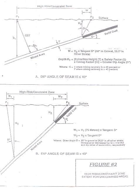
Figure 2. High Risk/Constraint Zone Extent for Undermined Areas. Click on image for larger version.
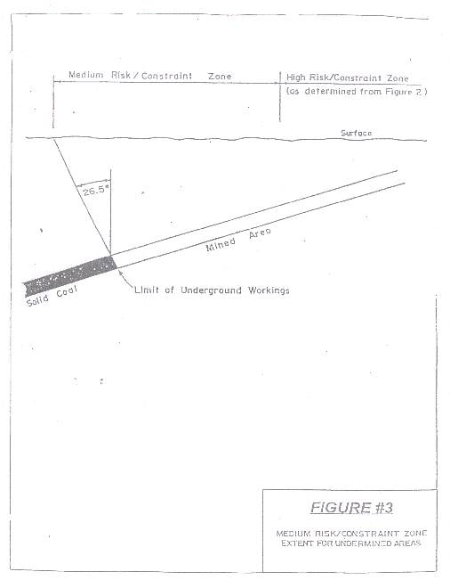
Figure 3. Medium Risk/Constraint Zone Extent for Undermined Areas. Click on image for larger version.
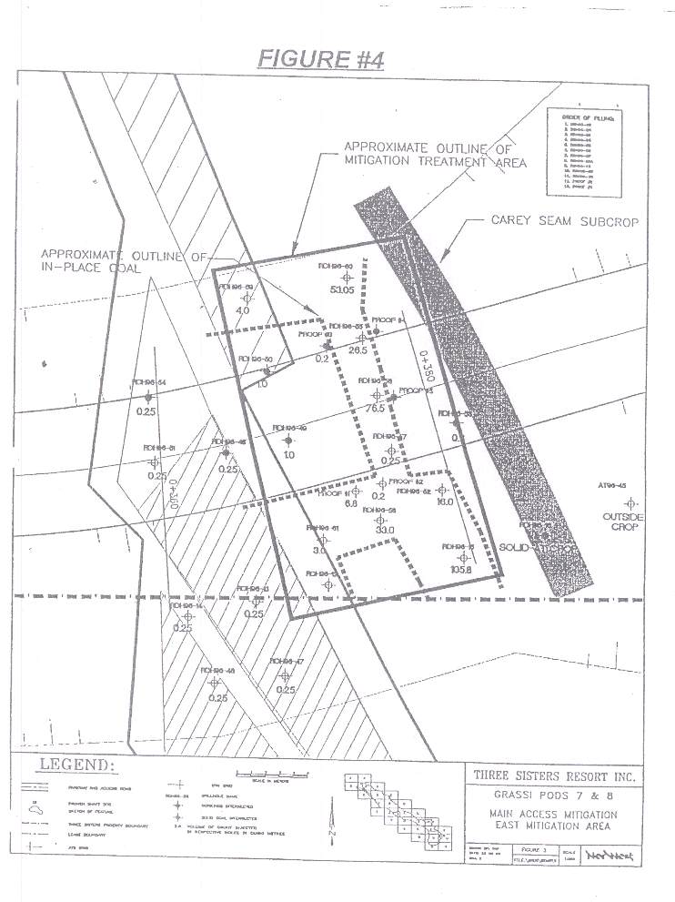
Figure 4. Schematic: Grassi Pods 7 & 8. Main Access Mitigation East Mitigation Area. Click on image for larger version.

Figure 5. Schematic: Grassi Pods 7 & 8. Main Access Mitigation West Mitigation Area. Click on image for larger version.
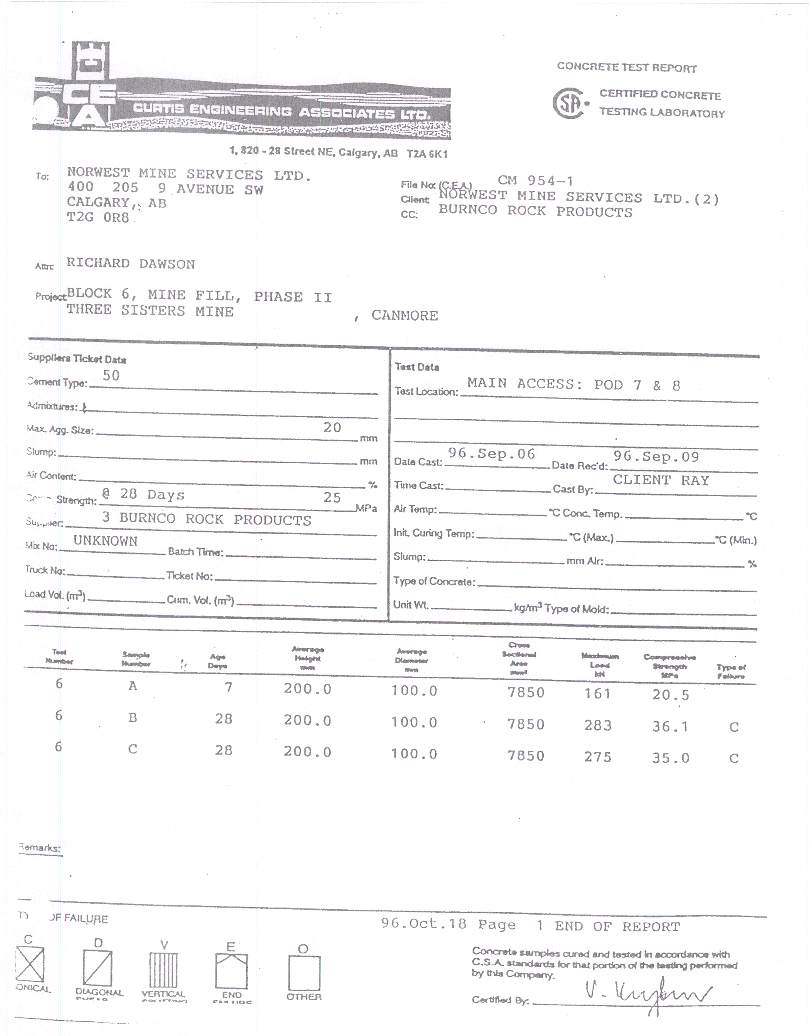
Concrete Test Report. (Click on image for larger version)
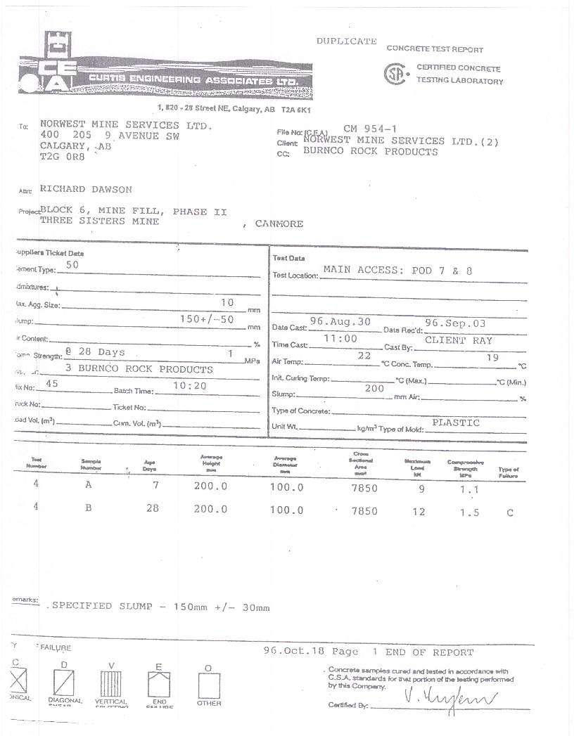
Concrete Test Report. (Click on image for larger version)
Note:
1 Patrick E. Gallagher is President of CTL Engineering of WV, Inc., 733 Fairmont Road, Morgantown, WV 26501 and has over 25 years of mine subsidence investigation and Stabilization experience.