

An Automated Roadway Pavement Marker Placement System: Phase 1 Report
Phase 1 Progress Report: November 1, 2007 - January 31, 2009
FHWA RFA Number DTFH61-08-G-00004
January 2009
Presented to:
Ms. Brittany Hall
US DOT / Federal Highway Administration
Office of Acquisition Management
1200 New Jersey Avenue, SE
Washington, DC 20590
Ms. Julie Zirlin
US DOT / Federal Highway Administration
Highways for LIFE Program Office
1200 New Jersey Avenue, SE
Washington, DC 20590
Submitted by:
Jonathan Shi, on behalf of
Stay Alert Safety Services, Inc.
272 Clayton Forest Drive
Kernersville, NC
Table of Contents
- 1. Summary
- 2. A Summary of the Major Activities in Phase 1
- 2.1 Work Performed in the Quarter of November-December 2007
- 2.2 Work Performed in the Quarter of January-March 2008
- 2.3 Work Performed in the Quarter of April-June 2008
- 2.4 Work Performed in the Quarter of July-September 2008
- 2.5 Work Performed in the Quarter of October-December 2008
- 2.6 The Suppliers of the Main Parts
- 3. Progress in Phase 1 (Task 1.3 in the original proposal)
- 3.1 The Delivery Sub-system (Task 1.3.1 in the original proposal)
- 3.2 The Adhesive Sub-system (Task 1.3.2 in the original proposal)
- 3.3 The Control Sub-system (Task 1.3.3 in the original proposal)
- 3.4 The Platform (Task 1.3.4 in the original proposal)
- 3.5 Initial Testing and Applications (Tasks 1.4 and 1.5 in the original proposal)
- 4. Commercialization Analysis
- 5. Conclusion
- Appendix A: Observations from the Independent Observers
1. Summary
According to FHWA's plan, the grant is divided into two phases: Phase 1 - Product redesign and building, and Phase 2 - Field Applications. Research and development activity of the grant officially started on November 1, 2007. Phase 1 ended on January 31, 2009. This report summarizes the progress accomplished in Phase 1.
In the 15 months, the project team has completely redesigned and rebuilt a new beta version of the proposed automated roadway pavement marker placement system. The new system went through rigorous workshop tests and was field tested to install raised pavement markers (RPMs) on roadways on November 12 and 13 in North Carolina. A FHWA expert, NCDOT representatives, and other independent observers joined the project team to observe the actual installation operations of the system. An initial field testing report was submitted to the FHWA in December 2008.
Based on comprehensive workshop and initial field testing results, it is concluded that the system design be technically sound; the beta version of the system be built properly with its robustness; and the system be safe and reliable for actual applications in the real world environment. The research team is ready to apply the system in actual RPM installation projects in Phase 2 of the grant. This report contains the following contents: a) a summary of the major research and development activities in Phase 1, b) progress accomplished, c) marketability analysis, and d) work plan for Phase 2.
2. A Summary of the Major Activities in Phase 1
The detailed research and development activities performed in Phase 1 were described in the four quarterly reports ending December 2007, March, June, and September 2008, the annual progress report, and the initial field testing report respectively. This section recaps the major activities.
2.1 Work Performed in the Quarter of November-December 2007
The major activity performed in the first two months of the grant falls in the following six areas:
- Signing separate agreements between the grant recipient and its two sub-recipients. After careful reviews, two sub-agreements were signed by the three parties. The parties showed their good will in the process which has created a collaborative culture for the team to move ahead with its planned research and development activities.
- Updating the work plan and schedule for Phase 1 according to the new timeline approved by FHWA. Phase 1 was divided in two stages: Stage 1 (Nov. 1, 2007 through Aug. 31, 2008) - product redesign and building, and Stage 2 - initial testing and evaluation.
- Studying the Georgia's RPM placement system. Funded by the Georgia Department of Transportation (GDOT), Georgia Tech has been undertaking a research and development initiative to develop a similar system. The project team carefully studied the Georgia's system. A teleconference was held with the participation of the two project teams.
- Conducting research on redesigning the four subsystems as outlined in the application. Research was conducted to study the following issues: the control panel, power supply, wireless operator pendant, storage magazines, hydraulic cylinders, and the glue pot.
- Brainstorming on new ideas for improving the product and meeting the needs of the end user. The project team discussed new ideas and strategies which may be able to further improve the product, for example, productivity, system reliability, and essential needs of the end user.
- Supporting communication efforts of the FHWA. The project team provided the program manager with a draft article for trade magazines and materials for preparing posters for the upcoming TRB annual conference.
2.2 Work Performed in the Quarter of January-March 2008
In the period between January 1 and March 31, 2008, the major activity focused on researching on designing the four subsystems as outlined in the application.
- The delivery sub-system includes a robotic arm which takes a marker from the storage stack at the back of the truck, delivers it to the right location on one side of the truck, and places it on the roadway. In the original prototype, a vacuum-style suction cup was used to pick up the RPM; a mechanic arm then delivered the marker to position and held onto it until it was placed on the road. The field tests indicated system reliability problems associated with the vacuum systems, air cylinders, and the pallet system. In the new design, hydraulic cylinders are used in the pallet to transport the RPM out and down on to the road. A vacuum system is powered with 12 volt electricity by using an air suction cup to hold the RPM and place it on the road. To compensate for the gravity from the downward motion of an RPM, the position where the RPM is temporarily held for the suction cup to pick up is installed with energy dispersion pad so that an RPM can land at the position properly regardless its height. A sensor is installed in the robotic arm to inform the system when it has made contact with the road, indicating a successful installation of the RPM.
- Adhesive flows through a hose to the tip that is positioned near the roadway and discharges the adhesive on the ground. The hose must maintain an approximate 500 degree temperature internally to enable the material to flow freely. The equipment used in the original prototype needs to be modified in order to significantly reduce the heat loss in the hose at the joints and at the tip. The tip area where the adhesive comes out is made of a heat resistant rubber that cannot hold the heat in. Heat loss is a big factor which slows down the placement of the RPMs because the operator must manually heat up the system with external torch heat. The research team studied various strategies to alleviate the problem.
- The project team reviewed the control panel and identified what input/output will be needed.
- The platform sub-system provides the space to mount the hardware components. It can be attached to a construction vehicle when there is a need for placing RPMs. The new design of this subsystem is integrated with stainless, aluminum and heavy gauge painted steel. Air bags are built into the system to relieve shocks when the truck hits bumps. The subsystem is portable with 2 major components that can be installed with a hilo to a main frame. The main frame is mounted to the truck.
2.3 Work Performed in the Quarter of April-June 2008
In the period between April 1 and June 30, 2008, the major activity concentrated on redesigning the system, and building some components. A 3D design drawing of the entire system is shown in Figure 1. Figures 2 and 3 show the front and back views of the system. Figure 4 shows the detailed design of the installation component.
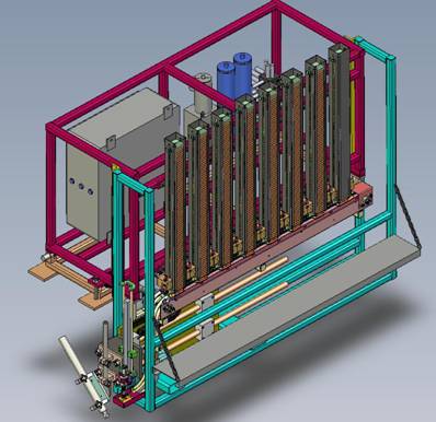
Figure 1: Entire System Design (3D View)
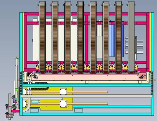
Figure 2: System Design (Front View)
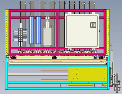
Figure 3: System Design (Back View)
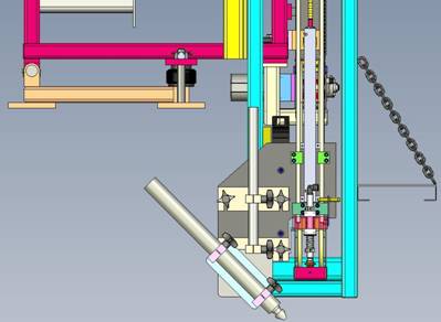
Figure 4: The Installation Component
2.4 Work Performed in the Quarter of July-September 2008
In the period between July 1 and September 30, 2008, the major activity focused on fine tuning the system design, and building individual components in the system. Figures 5 and 6 show the front and back views of the system. Figure 7 shows the picture of the installation component.

Figure 5: System Front View
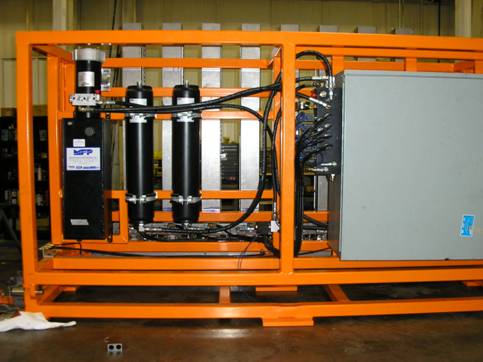
Figure 6: System Back View
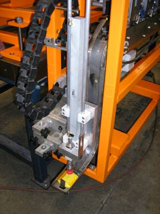
Figure 7: The Installation Component
2.5 Work Performed in the Quarter of October-December 2008
The Beta version of the road pavement marker (RPM) installation system was designed and built by Detail technologies in Phase 1 of the grant. The system was shipped to Stay Alert for planned initial field testing in November 2008.
Stay Alert organized a comprehensive field testing of the system during November 12-13, and followed with more testing of the system by its installation crew. Independent observers from the FHWA, NCDOT, and 3M were invited to observe the operation of the system in actual working conditions. The entire team, including three key members of the engineering group from Detail Technologies, three key members of the application group from Stay Alert, and the Consultant were all involved in the initial testing.
The initial field testing has exceeded the early expectation. The system design is technically sound. The beta version of the system is built properly with its robustness. The initial testing shows that the system is safe and reliable for actual applications in the real world environment. The research team submitted an initial application report to the FHWA in December 2008 with two independent assessment reports of the system from the observers of 3M and NCDOT.
Initial field testing details are provided in Section 3.5.
2.6 The Suppliers of the Main Parts
The system was built by using standards parts if possible. The main parts installed in the machine and their manufacturers are as follows:
- Allen Bradley MicroLogix 1500 PLC
- Banner- photo eyes (puck present)
- Turck- proximity sensors for conveyor position
- E'Mation Controls- Wireless pendent control
- Allen Bradley- solid state control relay for conveyor
- Hoffman R3- enclosure for main controls
- Square D- Disconnect for power control to main panel
- Square D- selector switches and push buttons 22.5 mm
- Parker- for hydraulic pump
- Parker- for hydraulic motor that turns conveyer
- Michigan Fluid Power- for hydraulic valve manifold
- Nason-for all hydraulic cylinders
3. Progress in Phase 1 (Task 1.3 in the original proposal)
As outlined in the original proposal, the automated RPM placement system consists of four sub-systems: 1) the delivery sub-system for moving markers in the construction vehicle, 2) adhesive sub-system for applying adhesive on the roadway, 3) the control subsystem, and 4) the platform for mounting the hardware components. The following sections describe the progress accomplished in these components.
3.1 The Delivery Sub-system (Task 1.3.1 in the original proposal)
The delivery sub-system includes a conveyor which moves a marker from a storage magazine to the landing area and a robotic arm which picks up the marker from the landing area at the back of the truck, delivers it to the right location, and places it on the roadway. As outlined in the original proposal, three components in this subsystem have been successfully redesigned and rebuilt: a) the vacuum cup, b) air cylinders, and c) the pallet system.
a. The vacuum cup: The old prototype used an air compressor supply system which could cause moisture to transfer through the air lines. Once moisture got into the pneumatic valves, the valves tended to fail. The new vacuum system as shown in Figure 8 has been redesigned and rebuilt with a two-directional hydraulic system which can reliably pickup a marker and release the marker as needed. Comprehensive workshop and initial field testing shows that the new system has the needed high reliability.
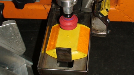
Figure 8: The Vacuum Sucking Cup
b) The delivery arm: Air cylinders were used in the old prototype which showed shortcomings at the field tests when grit and grime got in these cylinder shafts due to rough outdoor road conditions. These cylinders are replaced with a robust hydraulic system in the new system as shown in Figure 9. The delivery arm can stretch up to 2 feet to adjust its position for placing the marker. Comprehensive testing has shown that the new system is reliable and efficient in delivering and placing markers.
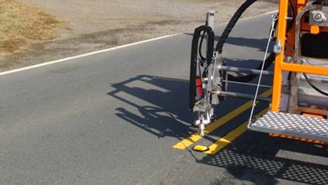
Figure 9: The Delivery Arm Can Stretch 24 Inches to Adjust Its Installation Position
c) The pallet system: A pallet system with 8 storage magazines as shown in Figure 10 is redesigned to hold up to 500 RPMs. All the magazines are installed on the frame. Two different types of markers can be stored in the magazines. The operator can choose either a yellow or a white marker to be placed. After one magazine is empty or jammed, the next magazine will be automatically activated.
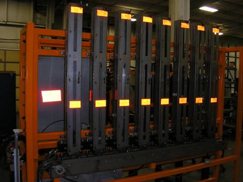
Figure 10: The Marker Storage Magazines
Each magazine is installed with a dispenser which can push one marker out of the magazine at a time. As shown in Figure 11, the dispenser is driven by a hydraulic cylinder. In comparing to the old prototype, the new system is much more reliable. The plumbing of hydraulic lines to each cylinder is progressing. Each cylinder is plumbed separately to a manifold of valves. A sensor has been mounted to each magazine to identify if any markers are ready upon demand.
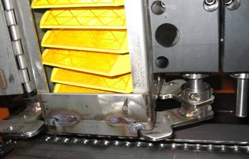
Figure 11: Marker Storage Magazine and Dispenser
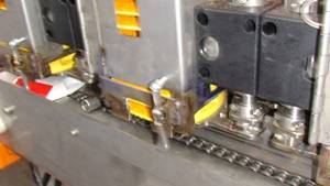
In the old prototype, a marker fell on its gravity. It caused problems during operations. For instance, a marker might jump out of the pallet when it came down from a far magazine with a long travel path; on the other hand, a marker might stop in the pallet when it came from the nearest magazine with a short travel distance. The new design uses a dog to catch and move the marker horizontally to the left side. As shown in Figure 12, the chain is installed with two dogs, one on the top and the other at the bottom (not visible in the figure), to continuously move the markers that are dispensed from their storage magazines. The chain is driven by a hydraulic cylinder. The hydraulic motor is mounted and is plumbed. A sensor is mounted to the chain system to know the position of the dog. The new system has been tested with an extremely high reliability.
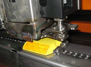
Figure 12: The Marker Mover
3.2 The Adhesive Sub-system (Task 1.3.2 in the original proposal)
Adhesive flows through a hose to the tip that is positioned near the roadway and discharges the adhesive on the ground. The hose must maintain an approximate 500 degree temperature internally to enable the material to flow freely. Heat loss is a big factor which slows down the placement of the RPMs because the operator must manually heat up the system with external torch heat. The tip area where the adhesive comes out is made of a heat resistant rubber that does not help hold the heat in. Currently, the adhesive system is provided by an independent manufacture, Sherwin Industries. The research team cannot make modifications to the system without the manufacturer's involvement. Instead, heating tapes are used to wrap up the entire hose and the cold spots as shown in Figure 13 to prevent heat loss. The initial field testing has shown that the measure has helped improve the performance of the subsystem.
In the meantime, the research team is working with the manufacturer to modify the system in order to significantly reduce the heat loss in the hose, at the joints, and at the tip. Sherwin Industries has shown its interest to partner with the research team in this area as we move forward. A representative from the manufacturer indicated they could relocate both the control panel and the junction box to fit our system design. He will also discuss with his engineers the possibility of removing the elbow connector at the end of the hose. It is expected that the adhesive subsystem will be modified to meet our system's need in Phase 2.
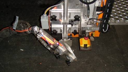
Figure 13: The Adhesive System
3.3 The Control Sub-system (Task 1.3.3 in the original proposal)
The control subsystem consists of two separate units which have been improved in the new system:
- The control panel: The control panel is the brain of the entire system. It instructs each component on when to perform what; it also controls the sensors to determine the status of the components in the system. As shown in Figure 14, the control subsystem is built in a box with all needed input/output ports. Extra ports are reserved for future enhancement. The control box is also installed with the control buttons which allow a direct operation of the system in the back of the truck. This feature is desirable especially at the testing stage. The initial field testing has shown that the subsystem is effective and provides an easy-to-use interface for the user to recode the control system with fault detection features as needed. For instance, when a marker was jammed in the first day of the field testing, the installation arm could not pick up a marker but continued its operation by pressing the sucking cup on the hot adhesive. The control engineer quickly recoded the control system with a fault detection feature which can warn the operator of the problem and abandon the remaining operations.
- A wireless operator pendant is supplied in the new system to allow the driver/operator to operate the system inside the truck. The remote unit as shown in Figure 15 can be powered from the cigarette lighter. The pendant has function buttons on it, such as power button, test adhesive, manual selector switches for each operation, automatic operation mode, and emergency shutdown. The unit can be enhanced with new features in Phase 2, such as adding an LCD screen to display text messages about the mode of the equipment and to provide safety warnings.
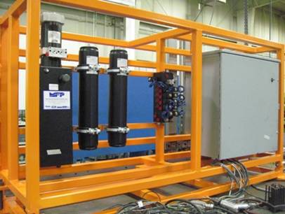
Figure 14: The Control Box
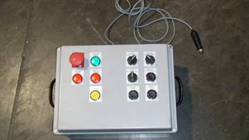
Figure 15: The Remote Control Device
3.4 The Platform (Task 1.3.4 in the original proposal)
The platform sub-system provides the space to mount the hardware components. It can be attached to a construction vehicle when there is a need for placing RPMs. As shown in Figures 16 and 17, the new design of this subsystem is integrated with stainless, aluminum and heavy gauge painted steel. In comparison to the old prototype, the new frame has the following two major advantages:
- Stronger and weather resistant. Considering harsh working conditions on the road, proper materials are selected to build the frame being much strong and being more resistant to any weather conditions.
- Weight distribution. The new design allows half of the frame to sit on the mounting truck so that a large portion of the weight of the system can be directly transferred to the base of the truck, instead of completely hanging from the truck as in the old prototype. Air bags are built into the system to relieve shocks when the truck hits bumps.
- Several adjustments are made to allow the frame to accommodate different types of trucks. The air cushion system was improved to handle more weight. Hilo tubes were installed for easily handling the unit during installation.
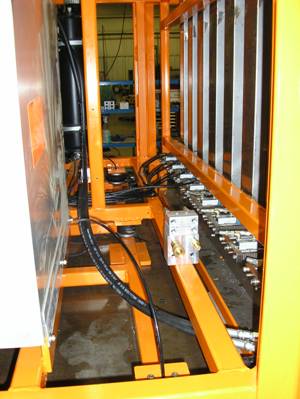
Figure 16: The Frame Structure
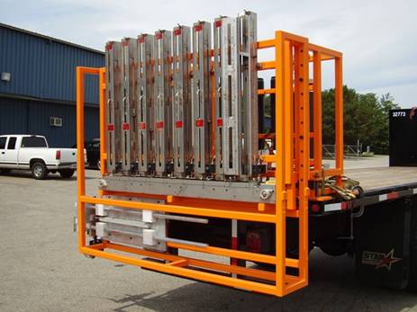
Figure 17: Back View of the Frame
3.5 Initial Testing and Applications (Tasks 1.4 and 1.5 in the original proposal)
To insure the system's high performance, different types of tests were performed in Phase 1. A component-based approach was used in building the system. After each component was constructed according to design, a comprehensive workshop test was first performed. Adjustments typically followed to ensure the performance of the component can meet or exceed the design expectation. After the entire system was assembled, it was again tested in the workshop and followed by needed refinements or adjustments. After the system's performance was determined stable and safe for field testing, the system was applied to install RPMs on the roadways in November 2008. This section summarizes these tests.
3.5.1 Tests conducted in the Detail Technologies workshop
Depending on the complexity and testing results, each component was extensively tested until it reached the expected performance reliability after it was built. The following log shows the amount of time that the major components have been tested.
- Cycle tested one de-gater/magazine system 5 Hrs
- Cycle tested one de-gater/magazine system 5 Hrs
- Cycle tested all eight de-gater/magazine systems, automated 20 Hrs
- Cycle tested all eight de-gater/magazine systems, automated 20 Hrs
- Cycle tested vacuum pick-up system 15 Hrs
- Cycle tested conveyor/chute/nest system 30 Hrs
- Cycle tested controller 10 Hrs
- Cycle tested entire system inside of Detail 10 Hrs
- Cycle tested entire system inside of Detail 10 Hrs
- Cycle tested entire system inside of Detail 10 Hrs
- Cycle tested entire system on Detail truck 10 Hrs
3.5.2 Initial testing and applications
The Beta version of the road pavement marker (RPM) installation system was designed and built by Detail technologies in Phase 1 of the grant. The system was shipped to Stay Alert for planned initial field testing in November 2008.
The initial field tests were conducted by the construction crew in the Stay Alert Inc by serving the following purposes: 1) training the construction crew, 2) testing working conditions of the product, and 3) making small adjustments as needed for the equipment to meet the conditions for full scale applications.
Stay Alert organized a comprehensive field testing of the system during November 12-13, and followed with more testing of the system by its installation crew. Independent observers from the FHWA, NCDOT, and 3M were invited to observe the operation of the system in actual working conditions. The entire team, including three key members of the engineering group from Detail Technologies, three key members of the application group from Stay Alert, and the Consultant were all involved in the initial testing.
a. Background
The purpose of the initial filed testing is to fully evaluate the functionality of the refined product and its suitability for more field testing and actual applications by the Contractor in Phase 2 of the grant. In Summer 2008, the program manager, Ms. Julia Zirlin of FHWA, the FHWA product expert, Mr. Carl Andersen, and the project team decided to conduct initial field testing in November 2008. A field testing was planned to apply the machine to install RPMs on actual roadways on November 12 and 13. Mr. Andersen of FHWA, NCDOT representatives, and other independent observers were invited to join the project team to observe the actual installation operation of the machine.
b. Observers involved in the two-day initial testing
The individuals observed or involved in the initial testing are divided into two groups: 1) the independent group, and 2) the research team.
The independent group has the following observers:
- Mr. Carl Andersen - Roadway Team Leader, Office of Research & Development, FHWA.
- Mr. Chris Howard - Transportation Mobility and Safety Division, NCDOT
- Mr. Timothy J. Inglis - Senior Government Transportation Safety Specialist, 3M - TSSD.
The entire project team has participated in the testing as follows:
- Jim Babcock - General Manager, Stay Alert Safety Services, Inc., the grant administrator
- Bryan Herrington - Detail Technologies/President, leader of the team of Detail Technologies
- Tony Collins - Project Manager, Stay Alert, Operator of the machine.
- Jonathan Shi - Professor of the University of Nebraska-Lincoln, Consultant and co-PI
- Jeff Erhart - Mechanic Engineer, Detail Technologies
- Eric Edwards - Control Engineer, Detail Technologies
- Shane Strickland - Installation Team Member, Stay Alert
c. Day 1 Test on Wednesday, November 12, 2008
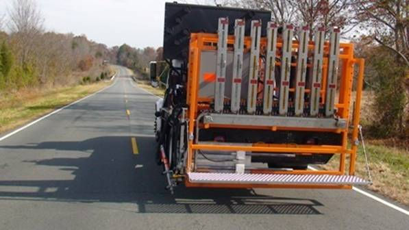
The field testing on Wednesday, November 12, was on Highway 158 starting at SR 1639 proceeding east in Davie County. The location was about one-hour away from the Stay Alert's workshop, where the machine was assembled and tested in the workshop. The machine was attached to the back of a normal RPM installation truck as shown in Figure 18.
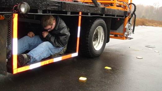
Figure 18: RPM installation truck
Before the machine was sent to the field, extensive testing was conducted in the workshop as shown in Figure 19 to test marker delivery, positioning, and installation operations. During the workshop testing, the adhesive subsystem was not used. The workshop testing provided a good opportunity to test the system's reliability and to debug the system in an efficient and safe manner. The observers were satisfied with what they saw during the workshop testing.
 |
 |
| Figure 19: Workshop Testing (a) positioning the marker, (b) picking up and placing the marker | |
When the truck was travelling to the installation site, it could safely travel at the regulatory speed limits on all categories of roadways including Interstate highways. The new design allows half of the frame to sit on the mounting truck so that a large portion of the weight of the system can be directly transferred to the base of the truck, instead of completely hanging from the truck as in the old prototype. Air bags built into the system can relieve shocks when the truck hits bumps. The driver didn't find it difficult to drive the truck.
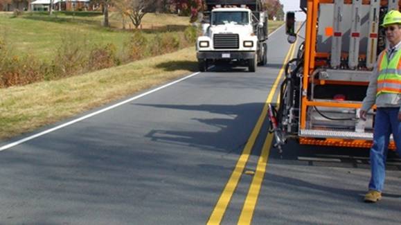
Figure 20: Installation operation at normal traffic conditions
The field testing started at 11:00 AM, and ended at 3:00 PM before the late afternoon rush hour. In the four-hour period, a total of 300 (280 yellow and 20 white) markers were placed in a distance of four miles. As shown in Figure 20, the installation was conducted at normal traffic conditions. Stay Alert provided traffic control during the installation.
The machine was operated by one person with a remote control. It worked very well in the first hour. Then it suffered a brief setback which lasted about forty minutes. After a long diagnosis, it was found that a loose coupling under the conveyor jammed the moving chain. After the problem was fixed, the installation resumed. In the remaining operation, the machine had a few more malfunctions, mostly caused by marks jammed in the conveyor system or in the storage magazines. The total downtime was about one hour and twenty-five minutes in the four-hour operation.
Independent observers from NCDOT and 3M observed part of the operation. The research team had been watching the entire operation and debugging the system as needed. The operator showed a great satisfaction of the system. Figures 21 through 24 explain the observed operations.
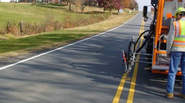
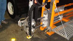
Figure 21: The cylinder can stretch 24 inches to adjust its installation position
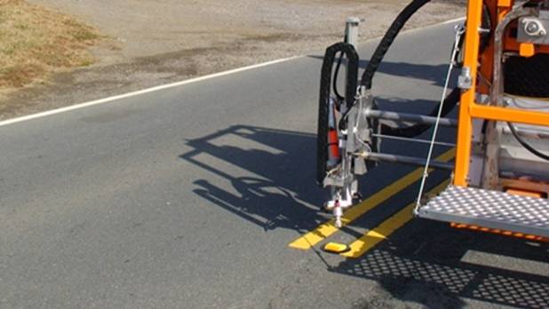
Figure 22: The marker was installed with the right amount of adhesive and force
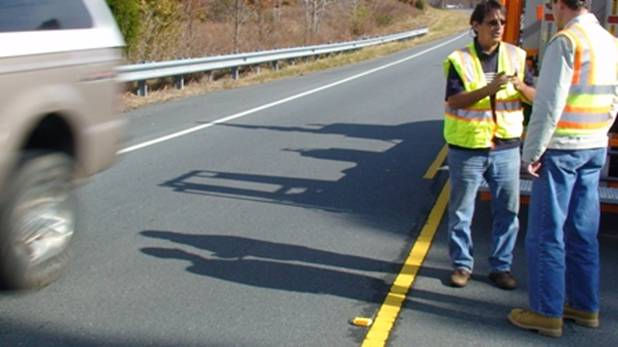
Figure 23: The installation quality cannot be better according to inspections
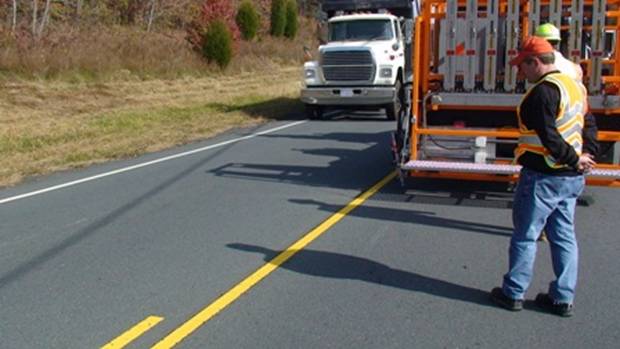
Figure 24: The robotic arm can be retracted when a large truck passes by to improve safety.
In general, the testing in the first day was a great success. However, the research team also discovered some bugs, such as:
- The stop position of the carry dogs was sometimes too close to the last magazine on the right. When a mark was released from the magazine, it might fall right on top of the dog and jam the conveyor system as shown in Figure 25(a). The solution was to reposition the sensor to an earlier location.
- Some rough joints/cuts in the storage magazines caught markers by their sharp edges and caused magazines to be jammed several times as shown in Figure 25(b). The solution was to grind off the rough edges and joints of the storage magazines.
- Fault detection was not available. When a marker was jammed, the installation arm could not pick up a marker but continued its operation by pressing the sucking cup on the hot adhesive. The solution was to recode the control system with fault detection features.
 |
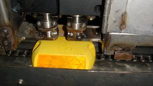 |
| Figure 25: (a) A marker jammed the conveyor (b) A marker jammed the magazine | |
In the evening, the research team went back to Stay Alert's workshop to implement the solutions. All problems discovered during the day were addressed properly. The machine was ready for another run.
d. Day 2 on Thursday, November 13, 2008
Although NCDOT issued a permit for the machine to be tested in a ten-mile stretch on Highway 150 on Thursday, November 13, 2008, the raining condition didn't allow RPM installation as originally planned.
Instead, a brainstorming meeting was conducted in the morning for Mr. Andersen of FHWA and the project team to discuss their observations and suggestions for further improvements to the system. It was unanimously agreed that the field testing in the first day was a great success. The system design is technically sound. The system is simple and robust. The testing didn't show any major defects in design and building of the system. The engineering team of Detail Technologies agreed to examine the following technical issues to further enhance the product:
- Considering modular design of marker magazines to fit different types of markers. This is an optional feature. There is no immediate need to put resources to study this problem. However, the project team realizes that this new feature will expand machine to a broader market.
- Adding a panel view to the control system to improve trouble shooting. This feature improves the user friendliness of the machine. The project team will design and build another remote control unit in phase 2. Before the new control unit is built, the existing control can still be used to operate the machine. It should be noted that the remote control as shown in Figure 15 is an independent component.
- Improving the heating system of the adhesive hose thru the adhesive system instead of the marker controller. This problem cannot be resolved shortly. The project team will work with the adhesive supplier to address the problem together in phase 2.
- Considering training/preventative maintenance for users. The crew in Stay Alert has been trained during the initial testing. Training and preventative maintenance will be addressed in phase 2.
- Updating engineering drawings. During the building and field testing processes, the designs of many components were modified. The engineering drawings must be updated before making a new unit. The technical team is currently working on it.
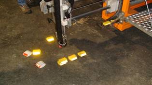
It was also agreed that Stay Alert crew should conduct more extensively testing of the machine. After the meeting, the system was re-tested in the workshop while the adhesive subsystem was disabled. Both yellow and white markers were released from the eight magazines as shown in Figure 26. The testing lasted for two hours and showed no problems that were encountered in the first day.
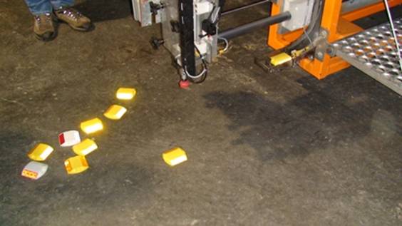
Figure 26: Workshop testing
In the early afternoon, light rain continued. It was decided to test the machine under wet conditions as shown in Figure 27. The testing was conducted in a private road with no traffic for safety reasons. The adhesive system was not activated. The main purpose was to test the delivery and installation operations under wet conditions. The testing lasted about two hours with more than 200 markers successfully placed on the ground. No major problem was encountered. The testing demonstrated that the problems encountered in the first day were entirely resolved. The machine was much more robust.
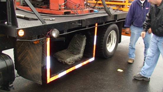
Figure 27: Testing under light rain
e. Additional testing
After the two-day initial testing, the Stay Alert team performed some additional testing of the system. First, they completed the remaining 2 miles on Highway 158. The markers are all bonded extremely well on the six mile stretch based on our inspection.
The machine was tested on another roadway during 10:00AM-4:00 PM, November 20, 2008. During the 6 hour operation, 427 markers were installed. There were a total of 12 system faults, which were caused by markers jammed at the landing area. This kind of problem can be easily and quickly fixed by removing the jammed marker and reset the system by the crew. It is worthwhile to note that the majority of the problem was due to inconsistency in the quality of markers, some of which had a distinctive edge which could slow them down when they came down the chute and could stop prior to reaching the landing area. As shown in Figure 28, the chute is like a slide. Some refinements can be made to enable markers to slide down consistently.
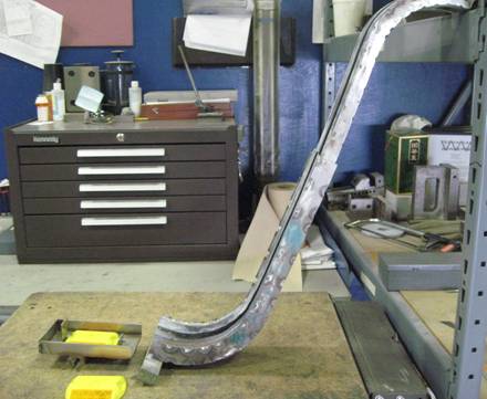
Figure 28: Marker Shooter in Raw Form
f. Summary of the initial testing
In conclusion, the initial field testing has exceeded the early expectation. The system design is technically sound. The beta version of the system is built properly with its robustness. The initial testing shows that the system is safe and reliable to be applied in the real world environment. Although small adjustments can be continuously made to improve the machine's performance and reliability, it is generally agreed that no major redesign or revision are immediately needed before Phase 2. Mr. Carl Andersen of the FHWA will submit his evaluation report separately. Two independent observers from 3M and NCDOT provided their assessment of the system as attached to this report in Appendix A.
4. Commercialization Analysis
As one of the drivers for this innovation, safety is the biggest benefit, and it has been demonstrated in the initial applications. In Phase 1, the project team has focused its effort on the system design and its technological feasibility. The limited field testing has demonstrated that the machine is safe for full scale applications. Full-scale field applications are essential to provide detailed system performance information for us to conduct a marketability analysis. As expected, a more detailed marketability analysis shall be available in Phase 2 report. The rest of the section presents different perspectives of the machine.
4.1 Proved Benefits
The initial field testing has demonstrated the following benefits of the innovation:
- Safety: The machine eliminates the person who faces high risk of being struck by vehicles on the roadway and occupational safety concern of being exposed to dangerous substance at a high temperature in a manual installation operation as shown in Figure 18.
- Labor savings: One person can operate the truck and the machine safely and smoothly. Therefore, one labor can be saved by using the machine.
- Quality. The RPMs installed using the machine bound on the roadway very well. Visual inspection and testing proved a high quality of the installed RPMs.
4.2 Construction Productivity
In the initial applications, the machine couldn't beat the production of a human crew. Several factors contributed to the outcome: a) skill of the operator, and b) system bugs. The operator did a good job in the initial applications. We observed a continuous improvement of efficiency in the initial application when the operator got more familiar with the machine. Training may further improve efficiency. During installation, various bugs or other reasons shut the process down from time to time. Many bugs were fixed in the two-day field testing. The improvement in efficiency in the third-day application was very significant (with 427 RPMs installed in 6 hours). As the identified refinements are to be completed in Phase 2, the machine's efficiency can be further improved. The machine is designed with a 6 second cycle time. Assuming 9 seconds for the truck to get to position, one marker can be installed in 15 seconds, which is translated as 240 markers per hour. This production rate is higher than a human crew. Therefore, it is possible that the machine can place as many or more marks as a man can. In Phase 2, the two full-scale applications will provide more detailed information on the machine's productivity.
4.3 Marketability
It is difficult to estimate the manufacturing cost of the machine at this moment because only one was made and much research was involved in manufacturing it. As a ballpark estimate, the cost to manufacture one unit is around $75,000K. If five units are to be made at a time, 10 percent savings are expected. The price may further come down with more research in Phase 2. Detail Technologies has the production capacity to manufacture one or multiple units as needed.
The project team cannot determine for certain whether the market can accept the innovation at the above referenced price. We have observed different perspectives from our communications and interactions with many highway professionals. From safety perspective, the innovation is well received. If the machine's efficiency can be further improved, it will become more attractive for contractors, who are typically paid by number of markers installed.
In Phase 2, the project team will gather more relevant information from field applications so that the picture shall become clearer.
5. Conclusion
The project team has successfully completed all research and developed tasks and has fully accomplished its objectives in Phase 1 of the grant as planned. It has completely redesigned and rebuilt a new beta version of the proposed automated roadway pavement marker placement system. The new system has been tested in the workshop and in the field to install raised pavement markers (RPMs) on actual roadways. The testing results show that the system design is technically sound; the beta version of the system is properly built with its robustness; and the system is safe and reliable for actual applications in the real world environment. We look forward to continue our work in Phase 2.
Appendix A: Observations from the Independent Observers
Comments from Mr. Timothy J. Inglis of 3M
3M Atlanta Sales Center 105 Crafton Park Lane
Cary, North Carolina 27519
919-225-3122
919-362-3831 (Fax)
3M
November 19, 2008
Mr. Jim Babcock
Stay Alert Safety Inc.
272 Clayton Forest Road
Kernersville, NC 27284
Dear Jim,
Thank you for your consideration in allowing us to participate in the testing of the Automated Raised Pavement Marker Machine that is under the FHWA Highways for LIFE grant program.
On Wednesday November 12, 2008, I had the opportunity to view and video the automatic installations of RPM on NC 158 in Davie County. Even thought NC 158 is a curvy two-lane road with higher than normal traffic, the automatic raised marker applicator did a great job of installing markers while providing safety to the workers and minimizing inconvenience to the motorist. From a technical perspective, I was particularly interested in how the 3M markers were being placed in the adhesive. A RPM placed in the adhesive too deep or not deep enough can deem the marker non-functional. The automated truck place the markers in the adhesive from what seemed to be the 'right' amount of pressure and with consistency that is difficult to replicate with human application.
Interstate RPM applications are very dangerous and un-nerving for the installer applying them the traditional way. It would be interesting to see (video) a comparison between the automatic marker truck and traditional application. The safety benefits and efficiency rates on a high volume interstate would be very telling.
I would once again like to thank you for this opportunity to view this innovative application. We at 3M take great pride in safety and support any efforts to increase it. Please do not hesitate to contact me with any questions.
Best Regards to you,
Timothy J. Inglis
Senior Government Transportation Safety Specialist
3M - TSSD
Comments from Mr. Chris Howard of NCDOT
From: Howard, Chris B [mailto:cbhoward@ncdot.gov]
Sent: 2008-11-17 11:45
To: Jim Babcock
Cc: Schleich, John E; Beard, Derrick H; King, Ronald; Couch, John P
Subject: Automated raised pavement marker machine
Jim,
Thanks for the inviting John Schleich/Standards Engineer, Derrick Beard/Standards Engineer and myself/Standards Project Design Engineer to observe the automated raised pavement marker machine on 11/12/08. I believe this is a great concept and wanted to briefly describe my observation regarding the traffic control and machine itself.
I understand we are all looking for increased productivity, but more importantly we cannot sacrifice safety. It seems this machine could improve the safety factor when applying raised markers. I believe an alternate traffic control for this operation on two, lane-two, way roadways with severe horizontal and vertical curves would be flaggers using a pilot car. This would alleviate the "starting and stopping" to allow traffic to pass safely on these roadways. The moving operation you used that day would be fine for multilane roadways. What really stood out was the elimination of a person physically installing the markers. Anytime we can eliminate people working in the center of the roadway is a plus.
The machine seemed to work really well for its first run. I did see a little dripping of the bitumen adhesive, but was no more than what I've seen in the pass applying markers the traditional way. Getting the correct setting or location of the markers in the center of the double yellow seemed to be a little tedious. Maybe you could use something similar to the pavement marker contractors, which is an arm in the front of the application truck that extends out (like a school bus) that the driver could use to stay in the center of the double yellow without having to look in the rear view mirror.
Once again, I think the real bonus of this machine is getting the individuals out of the center of the roadway. I was very impressed with its first real run and believe production will improve over time.
Thanks again,
Chris
Signing & Delineation Unit
NCDOT-Transportation Mobility and Safety Division
Office: (919)773-2909