Abbreviated Work Plan - Fully Precast Bridge Bents for Use in Seismic Regions
TECHNICAL ASPECTS OF THE INNOVATION

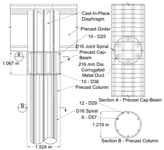
Figure 1. Typical Implementation of Product Concept
5.1 Technical Issues Addressed During Initial Project Development
During the initial product development, three main issues were addressed: (1) constructability of the system, (2) development of the large bars within the space available, and (3) seismic response of the precast connection compared with that of a typical cast-in-place reinforced concrete system.
Constructability. The main attraction of the proposed large-bar, large-duct precast system has been discussed in previous sections. By using precast elements, with a small number of large bars and ducts, it is possible to assemble a bridge bent quickly. The connection between column and cap beam is made with large bars that project from the top of the column and are grouted into ducts in the cap beam. The advantage of a small number of large bars (as opposed to numerous small bars) is the reduction in the number of alignments needed. The proposed system uses #18 bars in 8-in. diameter ducts to maximize assembly tolerances. Contractors have already indicated that these systems would be easy to construct and would save contractors and taxpayers much time and expense (Stanton et al. 2006).
Bar Anchorage Lengths. During the initial conceptual development of the proposed precast system, team members were concerned that the long anchorage lengths currently required for large bars would exceed the space available in typical cap beams. Development of these bars is particularly demanding under the cyclic loads caused by earthquakes. To address this concern, 14 pullout tests were performed with bars as large as #18. The tests and accompanying nonlinear finite element analyses showed that large bars confined by ducts and typical cap beam reinforcement can develop their yield and fracture stresses in as little as six and ten bar diameters, respectively (Steuck et al. 2008). The typical depth of cap beams (e.g., 42 in.) provides ample space to develop these large bars.
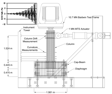
Seismic Performance of Solid Columns. A second early concern was that the large-bar system might not have the same seismic performance as a typical cast-in-place reinforced concrete system. To address this concern, cyclic tests were performed (Figure 2) on three variations of the large-bar precast, as well as, a typical cast-in-place connection (for comparison). All three variations of the precast system performed satisfactorily to a drift ratio of 5.5 percent, before longitudinal bars buckled and fractured. This level of deformation is approximately three times the demand expected in a major earthquake and is comparable with the deformation achieved with a cast-in-place system. This finding suggests that the large-bar, large-duct precast system has sufficient ductility capacity for all foreseeable seismic demands (Pang et al. 2008-1, Pang et al. 2008-2).

Figure 2. Column-Beam Connection Test Set-up
5.2 Technical Issues to be Addressed
The WSDOT-sponsored development has solved the key concerns of engineers, contractors, and fabricators. This section describes the remaining product development that will ensure that the system can be used in a wide range of applications. The four remaining issues to be addressed with the proposed work are (1) the incorporation of hollow columns into the system, (2) the use of segmental column units, (3) the deployment of the system in the field, and (4) the development of specifications for designing the product.
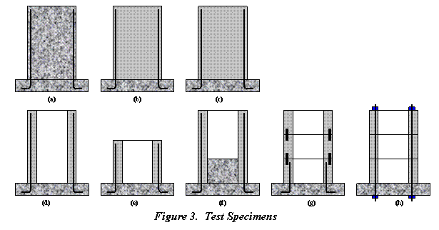
Laboratory testing is required to verify the structural effectiveness of the hollow-column configuration and match-casting process. The proposed specimens are shown in Figure 3 and are discussed below. Specimens (a), (b) and (c) represent a standard solid cast-in-place column (to be used as a reference), a solid precast column, and a solid precast column with partially debonded bars (to reduce the strain concentrations). These have already been tested and the data are available for comparison with the proposed specimens (d) though (h).

Figure 3. Test Specimens
Hollow Columns. The incorporation of a hollow-column option into the system would reduce the column weight. This is important if they are to be plant-cast and transported by road. If the columns are precast on site, use of a hollow section will reduce the size of the crane needed on site. However, hollow sections are potentially less desirable from a seismic point of view, because the concrete in them cannot readily be confined, and because they offer less resistance to shear. Both of these structural issues need to be verified. If the needed level of confinement cannot be achieved, the plastic hinge regions may be either made solid during precasting or filled with concrete after erection without serious impact on schedule.
With FHWA support, three specimens will be tested: Specimen (d) will be used to verify bending behavior of a hollow precast column, Specimen (e) will address shear, and Specimen (f) will determine the effect of adding a solid cast-in-place core to a hollow precast column. The test would be performed using the test setup shown in Figure 2.
Segmental Column Fabrication. The columns may be produced either as single pieces (preferable) or by match casting segments and joining them with epoxy, dowels, and potentially, post-tensioning. The column is likely to remain elastic over the majority of its height, so the detailing necessary for ductile response is likely to be required only at the top and bottom. Tests have already been conducted at the University of Washington on the use of unbonded post-tensioned columns, so the system is known to work in principle. However, those columns were cast as single pieces and were solid. Verification is needed to ensure adequate performance when post-tensioning is applied with hollow column sections. Test Specimens (g) and (h) are devoted to verifying the behavior of match cast components connected by dowels and post-tensioning.
Pilot Field Implementation.
The system should be built to demonstrate its feasibility in practice, taking into account the tolerances that must be maintained and the schedule to be achieved. If possible, some columns should be constructed by match casting and some should be produced in a plant, in order to verify the feasibility of both approaches. However, the feasibility of this depends on the job chosen for implementation of the precast bent system. Hollow columns up to 5-ft diameter can be precast in a plant, (Concrete Technology Corporation already makes hollow cylinder piles of approximately that size, although with a wall that is slightly thinner than that anticipated here) and larger ones would likely be site-precast.
Tri-State Construction has already constructed a precast cap beam on cast-in-place columns, and the success of that experience makes them eager to build a totally precast substructure. During the coming year, they have agreed to look for a bridge within those offered for bidding that is suitable for adoption of the system, so that they can demonstrate the effectiveness of the system by using it, at full scale, in the field. It is not possible at the time of submission of this pre-proposal to determine on which bridge the system will be demonstrated, because the bridge bidding and construction schedule is different from FHWA's schedule for awarding grants.
Design Specifications and Guidelines.
- Technical issues such as (1) the need for solid portions of the columns in expected seismic damage zones, (2) cap beam joint shear design limits, and (3) the effects of using post tensioning versus grouted sleeves to join column segments will be evaluated and design recommendations developed.
- A complete, detailed, design for a totally precast bridge bent should be conducted for both a single-column and a multi-column bent, and for spread footings and drilled shafts. The purpose would be to reveal (and correct) any weaknesses in the design as it is moved from concept to constructed facility.
- A substructure type selection guide that compares the benefits, challenges, costs, and project delivery aspects of using precast substructures in lieu of conventional cast-in-place construction will be developed to help guide designers, contractors, and owners in selecting one construction method over the other.
- Proposed AASTHO guide specification language will be developed for seismic design in accordance with the displacement-based approach of the newly adopted Guide Specification for LRFD Seismic Bridge Design.
Deliverables. The anticipated product from this work is a set of design configurations (e.g., example concrete outlines, configuration of internal reinforcement, suggested materials, and example integration details with typical girder-bridge superstructures and foundations). This will be accompanied by a set of design specifications that state which current LRFD provisions do not apply (because they are specific to cast-in-place construction) and then provide alternate substructure type selection guidance, design requirements, and design limits to be used for this system. The objective is to provide a complete system for designers to use immediately. To that end, example designs will also be provided to illustrate the application of the design methodology.

