Precast Bent System for High Seismic Regions, Final Report, Appendix A
APPENDIX A: DESIGN PROVISIONS
Publication No. FHWA-HIF-13-037-A
June 2013
Notice
This document is disseminated under the sponsorship of the U.S. Department of Transportation in the interest of information exchange. The U.S. Government assumes no liability for the use of the information contained in this document.
The U.S. Government does not endorse products or manufacturers. Trademarks or manufacturers' names appear in this report only because they are considered essential to the objective of the document.
Quality Assurance Statement
The Federal Highway Administration (FHWA) provides high-quality information to serve Government, industry, and the public in a manner that promotes public understanding. Standards and policies are used to ensure and maximize the quality, objectivity, utility, and integrity of its information. FHWA periodically reviews quality issues and adjusts its programs and processes to ensure continuous quality improvement.
|
1. Report No. FHWA-HIF-13-037-A |
2. Government Accession No. N/A |
3. Recipient’s Catalog No. N/A |
||||
|
4. Title and Subtitle PRECAST BENT SYSTEM FOR HIGH SEISMIC REGIONS APPENDIX A: DESIGN PROVISIONS |
5. Report Date June 2013 |
|||||
|
6. Performing Organization Code |
||||||
|
7. Author(s) M. Lee Marsh1, Stuart J. Stringer1, John F. Stanton2, Marc O. Eberhard2, Olafur S. Haraldsson2, Hung Viet Tran2, Bijan Khaleghi3, Eric Schultz3, and Steve Seguirant4 |
8. Performing Organization Report No. |
|||||
|
9. Performing Organization Name and Address 1BergerABAM, Inc. 33301 Ninth Ave South, Suite 300 Federal Way, WA 98003 2 University of Washington, Seattle, WA 3 Washington State Department of Transportation, Olympia, WA 4 Concrete Technology Corporation, Tacoma, WA |
10. Work Unit No. |
|||||
|
11. Contract or Grant No. DTFH61-09-G-00005 |
||||||
|
12. Sponsoring Agency Name and Address Federal Highway Administration Highways for LIFE Program Office 1200 New Jersey Avenue, SE Washington, DC 20590 |
13. Type of Report and Period Covered Final Report |
|||||
|
14. Sponsoring Agency Code |
||||||
|
15. Supplementary Notes This is an appendix to the final project report, Precast Bent System for High Seismic Regions (FHWA-HIF-13-037). |
||||||
|
16. Abstract The final report for this project provides information on the system concept, as well as the background physical testing for the upper level grouted duct connections and the lower socket type connections. Additionally, the report provides design and construction specifications, describes a demonstration project constructed in Washington State, and discusses lessons learned from the demonstration project. This report is a technical resource that provides background information on the use of a precast bent system for use in high seismic regions. The system is designed for, and intended to be used with, prestressed girder bridges that are built integrally with the supporting intermediate piers. Appendix A details design specifications which amend the provisions of the AASHTO Guide Specifications for LRFD Seismic Bridge Design (referred to in this report as the AASHTO Seismic Guide Specifications). As such, it is formatted per AASHTO requirements as an additional appendix to the Seismic Guide Specifications, where it is proposed to be appendix C. The design provisions of the AASHTO Seismic Guide Specifications apply to the Highways for LIFE precast bent system for seismic regions except as modified according to the provisions herein. All cross-references in this appendix are in relation to the second edition (2011) of the AASHTO Seismic Guide Specifications. There are two additional appendixes to the final report, published as stand-alone documents:
In addition, two companion reports cover the detailed testing and modeling of the spread footing and drilled shaft foundation versions of the precast column-to-foundation connection:
|
||||||
|
17. Key Words Bridges, earthquakes, accelerated bridge construction, precast bent, connections, spread footing foundations, drilled shaft foundations, prefabricated bridge elements and systems |
18. Distribution Statement No restrictions. This document is available to the public through the National Technical Information Service, Springfield, VA 22161. |
|||||
|
9. Security Classif. (of this report) Unclassified |
20. Security Classif. (of this page) Unclassified |
21. No. of Pages 20 |
22. Price |
|||
| APPROXIMATE CONVERSIONS TO SI UNITS | APPROXIMATE CONVERSIONS FROM SI UNITS | ||||||||
|---|---|---|---|---|---|---|---|---|---|
| Symbol | When You Know | Multiply By | To Find | Symbol | Symbol | When You Know | Multiply By | To Find | Symbol |
| LENGTH | LENGTH | ||||||||
| in | inches | 25.4 | millimeters | mm | mm | millimeters | 0.039 | inches | in |
| ft | feet | 0.305 | meters | m | m | meters | 3.28 | feet | ft |
| yd | yards | 0.914 | meters | m | m | meters | 1.09 | yards | yd |
| mi | miles | 1.61 | kilometers | km | km | kilometers | 0.621 | miles | mi |
| AREA | AREA | ||||||||
| in2 | square inches | 645.2 | square millimeters | mm2 | mm2 | square millimeters | 0.0016 | square inches | in2 |
| ft2 | square feet | 0.093 | square meters | m2 | m2 | square meters | 10.764 | square feet | ft2 |
| yd2 | square yards | 0.836 | square meters | m2 | m2 | square meters | 1.195 | square yards | yd2 |
| ac | acres | 0.405 | hectares | ha | ha | hectares | 2.47 | acres | ac2 |
| mi2 | square miles | 2.59 | square kilometers | km2 | km2 | square kilometers | 0.386 | square miles | mi2 |
| VOLUME | VOLUME | ||||||||
| fl oz | fluid ounces | 29.57 | milliliters | ml | mL | milliliters | 0.034 | fluid ounces | fl oz |
| gal | gallons | 3.785 | liters | L | L | liters | 0.264 | gallons | gal |
| ft3 | cubic feet | 0.028 | cubic meters | m3 | m3 | cubic meters | 35.314 | cubic feet | ft3 |
| yd3 | cubic yards | 0.765 | cubic meters | m3 | m3 | cubic meters | 1.307 | cubic yard | yd3 |
| NOTE: Volumes greater than 1000 l shall be shown in m3 | |||||||||
| MASS | MASS | ||||||||
| oz | ounces | 28.35 | grams | g | g | grams | 0.035 | ounces | oz |
| lb | pounds | 0.454 | kilograms | kg | kg | kilograms | 2.202 | pounds | lb |
| T | short tons (2000 lb) |
0.907 | megagrams | Mg | Mg (or "t") | megagrams (or "metric ton") |
1.103 | short tons (2000 lb) | T |
| TEMPERATURE (exact degrees) | TEMPERATURE (exact degrees) | ||||||||
| °F | Fahrenheit | 5(F–32)/9 or (F–32)/1.8 | Celcius | °C | °C | Celsius | 1.8C +32 | Fahrenheit | °F |
| ILLUMINATION | ILLUMINATION | ||||||||
| fc | foot–candles | 10.76 | lux | lx | lx | lux | 0.0929 | foot–candles | fc |
| fl | foot–Lamberts | 3.426 | candela/m2 | cd/m2 | cd/m2 | candela/m2 | 0.2919 | foot–Lamberts | fl |
| FORCE and PRESSURE or STRESS | FORCE and PRESSURE or STRESS | ||||||||
| lbf | pounds | 4.45 | newtons | N | N | newtons | 0.225 | poundforce | lbf |
| lbf/in2 | pound per square inch | 6.89 | kilopascals | kPa | kPa | kilopascals | 0.145 | poundforce per square inch | lbf/in2 |
*SI is the symbol for the International System of Units. Appropriate rounding should be made to comply with Section 4 of ASTM E380. (Revised March 2003)
PREFACE
The following are design specifications which amend the provisions of the AASHTO Guide Specifications for LRFD Seismic Bridge Design. As such, it is formatted per AASHTO requirements as an additional appendix to the Seismic Guide Specifications, where it is proposed to be appendix C. The design provisions of the Seismic Guide Specifications apply to the Highways for LIFE precast bent system for seismic regions except as modified according to the following provisions. All cross-references within this appendix are in relation to the second edition of the Seismic Guide Specifications (2011).
Appendix C to AASHTO Guide Specifications for LRFD Seismic Bridge Design: Design Requirements
PRECAST BENT SYSTEM FOR SEISMIC REGIONS DEVELOPED UNDER Highways for LIFE Technology Partnerships Program
TABLE OF CONTENTS
C-3.3 – EARTHQUAKE-RESISTING SYSTEMS (ERS) REQUIREMENTS FOR SDCS C AND D
C-4.8.1 – Local Displacement Capacity for SDCs B and C
C-4.11.6 – Analytical Plastic Hinge Length
C-6.3.10 – Socket-Type Footing Connections (New Article)
C-8.6.10 – Interface Shear Transfer Capacity of Precast Bent Systems (New Article)
C-8.8.4 – Minimum Development Length of Reinforcing Steel for SDCs C and D
C-8.8.7 – Lateral Reinforcement Inside the Plastic Hinge Region for SDCs C and D
C-8.8.10 – Development Length for Column Bars Extended into Oversized Pile Shafts for SDCs C and D
C-8.8.12 – Lateral Confinement for Oversized Pile Shafts for SDCs C and D
C-8.13.2 – Joint Proportioning
C-8.13.3 – Minimum Joint Shear Reinforcing
C-8.14.1 – Horizontally Isolated Flares
C.1 – INTRODUCTION
A fully precast bent system was developed under the Highways for LIFE Technology Partnerships Program under Grant No. DTFH61-09-G-00005. This appendix provides the design specification requirements for the seismic design of the bent system, which is abbreviated as the HfL Bent System. Modifications or additions to the requirements of the AASHTO Guide Specifications for LRFD Seismic Bridge Design are provided herein.
C.2 – DESCRIPTION OF SYSTEM
The bent system comprises precast columns supported by either spread footings or drilled shafts and a precast cap beam that supports prestressed concrete girders. The bent is integrated with the superstructure using a cast-in-place full concrete diaphragm. The cap beam thus created is a two-stage dropped cap beam, with the lower precast portion known as the first stage cap and the upper diaphragm known as the second stage cap. The deck slab is cast on top of the girders and diaphragm. This concept is illustrated in Figures C-1 and C-2 and in Figure 4.11.2-2.
The system connections consist of a socket connection at the foundation level and a grouted bar connection to the cap beam. The foundation must be cast around the precast column to form the socket connection, and the interface between the column and foundation must be intentionally roughened to ensure vertical load carrying capacity. In the HfL Bent System, the connection to the cap beam is intended to consist of large diameter bars such that fewer bars are required. These bars are grouted into steel ducts with generous diameters relative to the bars (2 to 3 inches larger in diameter) to facilitate fit up.
The precast column may also be divided into segments to reduce handling weights. For many typical bridges, a single precast column element is sufficient. However, the segmental column concept was included in the validation and HfL demonstration project.
Validation testing of the HfL Bent System was conducted by the University of Washington, and the results are reported in Pang et al. (2008), Haraldsson et al. (2013), Hung et al. (2013), and Marsh et al. (2013). Additionally, a demonstration project was constructed by the Washington State Department of Transportation over Interstate 5 south of Olympia.
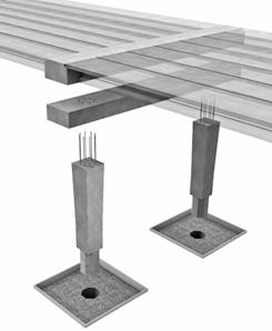
Figure C-1: Precast bent system, exploded view

Figure C-2: Elevation of column and pier.
C.3 – DESIGN SPECIFICATIONS
The articles below provide additional requirements to those in the main body of the Guide Specifications for LRFD Seismic Bridge Design, and these requirements shall be followed when designing an HfL Bent System. Articles of the main specification that are not changed herein apply to the design of the bent system and therefore still apply.
C-3.3 – EARTHQUAKE-RESISTING SYSTEMS (ERS) REQUIREMENTS FOR SDCS C AND D
The HfL Bent System may only be used with Types 1, 3, 4, and 5 ERS, as illustrated in Figure 3.3-1a. The Earthquak Resisting Elements (EREs) permitted within the bent are Type 1, 2, 7, 8, and 13, as illustrated in Figure 3.3-1b. No other EREs are permitted when the HfL bent is used.
Although the EREs are in the permissible category, the HfL Bent System, itself, is only permissible with Owner’s approval.
The HfL Bent System has only been validated with spread footings, drilled shafts, and plastic hinging restricted to the columns. Due to the limited application of the system, the EREs are all considered permissible with Owner’s approval. As experience is gained with the system, this restriction may be eased.
The Global Design Strategy of bridges that use the HfL Bent System are expected to be Type 1 systems, because the validation has been conducted only on such systems. Type 3 systems could be designed using the HfL Bent System, although additional development effort would be required. The system as currently developed relies on a two-stage cap beam that is integral with an open soffit girder superstructure. There is currently no configuration for a nonintegral bent, which would be required with a Type 3 Global Design Strategy.
C-4.8.1 – Local Displacement Capacity for SDCs B and C
Equations 4.8.1-1, 4.8.1-2, and 4.8.1-3 may be used to assess the local displacement capacity of the HfL Bent System in SDCs B and C.
C-4.11.6 – Analytical Plastic Hinge Length
Equations 4.11.6-1 and 4.11.6-3 apply to the HfL Bent System without modification.
The HfL Bent System is an emulative system that behaves similarly to cast-in-place (CIP) systems of the same configuration. Validation testing reported by Pang et al. (2008), Haraldsson et al. (2013), and Hung et al. (2013) has shown that the calculations of displacement capacity, including the analytical plastic hinge length and other elements of the procedure, may be performed using the same approach as for CIP elements.
C-6.3.10 – Socket-Type Footing Connections (New Article)
Where socket-type connections are used to connect precast columns to CIP spread footings or pile caps, the following requirements shall be followed.
The interface of the precast column with the footing shall be intentionally roughened to an amplitude of 0.70 inches. The column-to-footing shear interface shall be designed for interface shear using Article 5.8.4 of the AASHTO LRFD Bridge Design Specifications. To account for potential shrinkage cracking around the column, the cohesion factor, c, shall be taken as zero. The friction factor, m, and the factors K1 and K2 may be taken as those for normal-weight concrete placed against a clean concrete surface.
The shear friction bars need not cross the interface between the column and footing. Instead, the bars that would normally pass across this interface shall be placed at the same level in the footing adjacent to the column. Because typical footings have an orthogonal layout of reinforcement, bars at 45 degrees to the footing reinforcement are also required. These additional bars should be of the same size as the main footing reinforcement and be fully developed at the projection of the perpendicular column face. It is recommended that four bars be placed at each of four locations around the column. Such additional bars shall be placed near the top and bottom reinforcement of the footing.
With a socket-type connection it is not practical to turn the column bars out with 90-degree hooks. Therefore, column bars shall be terminated with mechanical anchorages capable of developing the column bar specified ultimate tensile strength (Class HA per ASTM A970). These anchorages shall be placed below the bottom mat of footing reinforcement to develop a complete joint force transfer mechanism. The placement of the anchorages will require additional space beneath the bottom mat of reinforcement.
The soil directly beneath the column must support the column and associated construction loads before the footing concrete gains sufficient strength. If necessary, a small slab beneath the column may be necessary to provide appropriate column support during construction.
The placement of the footing bars is shown in Figure C-C6.3.10-1.
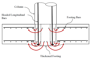
Figure C-C6.8.10-1 – Placement of footing bars with a socket-type connection
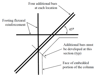
Figure C-C6.8.10-2 – Placement of additional bars at 45 degrees to the main footing reinforcement
C-6.5 – DRILLED SHAFTS
Where socket-type connections are used to connect precast columns to drilled shafts (or pile shafts), the column-to-shaft side interface shall be intentionally roughened to an amplitude of 0.70 inches. Because axial loads can be supported by end bearing of the column on the shaft, a shear friction interface design is not required. However, consideration shall be given to temporary support of the precast column and to proper consolidation of concrete between the column base and shaft to ensure that an adequate load path is provided.
Additional requirements are provided in Article C-8.8.12.
C-8.1 – GENERAL
Precast columns and cap beams used with the HfL Bent System are covered by Section 8. The columns of such systems are not considered precast concrete piles.
C-8.6.10 – Interface Shear Transfer Capacity of Precast Bent Systems (New Article)
The interface shear capacity between precast column and cap beam or between segments of precast columns shall be determined using Article 5.8.4 of the AASHTO LRFD Bridge Design Specifications. To account for cyclic loading effects and the potential for significant cracking, the cohesion factor, c, shall be taken as zero and the friction factor, m, shall be 0.60. The factors K1 and K2 shall be 0.2 and 0.8 ksi, respectively.
C-8.8.3 – Splicing of Longitudinal Reinforcement in Columns Subject to Ductility Demands for SDCs C and D
Where tensile force is transferred between reinforcing anchored into steel ducts using high-strength grout and bars adjacent to the duct, the splice length, lsplice, shall be the longer of the anchorage length of the bar inside the duct, as given by Article C-8.8.4, or the splice length of the bars on the outside of the duct as determined by Article 5.11.5 of the AASHTO LRFD Bridge Design Specifications.
To the extent practical, the bars spliced to the duct should be arranged to minimize eccentricity and should be in contact with the duct. If bars are placed away from the duct, the non-contact distance must be added to the splice length.
Transverse steel shall enclose both the duct and the bars outside the duct.
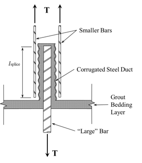
Figure C-C8.8.3-1 – Splicing of Grouted Duct Bars to Other Bars.
C-8.8.4 – Minimum Development Length of Reinforcing Steel for SDCs C and D
The anchorage length for column bars developed into steel ducts shall satisfy:
where:
dbl = diameter of longitudinal column bar (in.)
fye = expected yield stress of the longitudinal reinforcement (ksi)
f’g = nominal compressive strength of the grout (ksi)
When bars are anchored into steel ducts, the force that is transferred to the duct must then be transferred to adjacent reinforcement. In addition to the development length provided in Eq. 8.8.4-1, the length of the embedment must consider the splice length required and configuration (i.e., non-contact distance) of the bars outside of the duct, to which the tensile force is transferred.
The ducts used shall be steel and be of semi-rigid corrugated construction. Axial force shall not be transferred beyond the end of the bar anchored within the duct without testing to demonstrate that the duct has the capacity to withstand the expected tensile force.
The ratio of duct-to-bar diameter shall not exceed 6.
In the case of dropped cap beams, where ducts anchor column reinforcement in the first or lower stage cap beam, but the superstructure is integral with the upper cap beam, all column bars must extend into the upper cap. These bars should extend as far as practical to the top of the upper cap.
In the event that a limited number of column bars need to be terminated in the lower cap, a rational analysis, such as strut-and-tie analysis, shall be conducted to account for the actual distribution of forces transferred from the column bars to the cap beam.
Testing by Eberhard et al. (2009) showed that large reinforcing bars can be developed in shorter lengths than normal, if the bars are grouted into steel ducts. The bars can develop their ultimate strength if grouted at least 16 bar diameters into the ducts. This length allows for cyclic degradation and is based on developing at least 95 ksi bar stress with grout strengths of 8 ksi. Eq. 8.8.4-1 provides adjustment for grout strength and assumes the ultimate strength of the bar is 1.4 times the expected yield strength.
The length of the duct used to anchor grouted bars may be controlled by either the bar grouted into the duct, as provided by Eq. 8.8.4-1, or the normal splice length of the bars on the outside of the duct. Additionally, if such bars are not adjacent to the duct, then the non-contact distance should be added to the splice length.
For smaller applications, corrugated post-tensioning duct is adequate. For anchorage of larger bars, corrugated steel pipe conforming to ASTM A760 may be used. Typically, such pipe would be galvanized.
The ducts are intended to provide local confinement, crack arresting, and provide a roughened surface to facilitate shear transfer from the bar anchored inside to the adjacent concrete. The ducts are not intended to resist tensile forces.
Because the joint shear force transfer between the vertical system and superstructure takes place in the upper cap beam, the column bars must be extended into the upper cap. The effect of the lower cap is to distribute forces along the cap and thereby enlarge the effective joint shear region.
C-8.8.7 – Lateral Reinforcement Inside the Plastic Hinge Region for SDCs C and D
Where precast columns connected with grouted bedding layers are used, lateral reinforcement may be required within the bedding layer. The maximum spacing of lateral reinforcement applies inclusive of the bedding layer. Lateral reinforcement included in the bedding layer shall be of the same size as that in the column itself. If stronger materials are used for reinforcement of the bedding layer, the assumed material strength for design shall be the same as that used for the column.
If cross-slope results in a varying thickness of the grout bedding layer, the largest thickness shall be used to configure the lateral reinforcement.
C-8.8.10 – Development Length for Column Bars Extended into Oversized Pile Shafts for SDCs C and D
Where socket connections are used, column bars may be terminated with straight bar embedment or mechanical anchorages capable of developing the column bar to the specified ultimate tensile strength (Class HA per ASTM A970).
All column bars may be terminated at the same location, provided the confinement steel of C-8.8.12 is included.
The bars shall be extended into the transition or splice zone of the pile shaft a distance equal to the standard Class C splice length as determined by the controlling case of column or shaft bars. Additional lap length must be added for the non-contact length between column and shaft bars. The embedment depth must meet the following:
le = ls +e + c (C-8.8.10-1)
where:
le = total embedment length of precast column,
ls = Class C splice length of controlling bar (in.), 1.7lac, as determined by Eq. 8.8.4-1.
e = largest center-to-center distance between column and shaft bars (in.)
c = total bar end cover distance of both column and shaft bars (in.)
The lap length of the column longitudinal reinforcement with the pile shaft reinforcement must account for all bars being spliced at once using a Class C splice, and the lap length must include the additional non-contact distance, e, between the column and shaft bars as shown in Figure C-C8.8.10-1
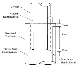
Figure C-C8.8.10-1 – Column-to-shaft longitudinal bar arrangement
C-8.8.12 – Lateral Confinement for Oversized Pile Shafts for SDCs C and D
Where socket connections of precast columns are used to connect columns with pile shafts, adequate confinement reinforcement must be included to react the internal tension forces that develop. Lateral confinement reinforcement along the column embedment length shall satisfy:
where:
Ash = area of lateral confinement steel –one leg of spiral or welded hoop (in.2)
smax = spacing between lateral confinement steel (in.)
k = efficiency factor, taken as 1 over the upper half of the embedment length and 0.5 over the lower half.
ful = tensile strength of column longitudinal reinforcement (ksi)
Al = total area of column longitudinal reinforcement (in.2)
fytr = yield strength of lateral or transverse reinforcement (ksi)
ls = length of required Class C splice (in.)
Over the upper 1 foot of the shaft confinement length, the transverse reinforcement content shall be doubled from that used otherwise for the upper half of the embedment length.
Lateral confinement reinforcement in the oversized pile shaft shall be permitted to be developed by welding of a spiral onto itself, provided the weld is designed to develop the strength of the spiral.
The confinement reinforcement requirements over the top portions of oversized pile shafts that connect with precast columns are included to provide tie reinforcement to react prying forces introduced near the top of the shaft by the precast column. Experimental testing by Hung et al. 2013 showed that adequate strength may be achieved in such connections, provided the lateral confinement reinforcement as defined by Eq. 8.8.12-1 is included. The additional confinement reinforcement required over the upper half of the embedment length is intended to limit potential shaft damage, which tends to occur at the top of the shaft if adequate confinement is not provided.
The configuration of the tie reinforcement is shown in Figure C-C8.8.12-1.
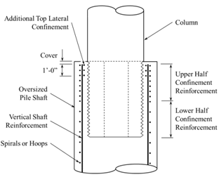
Figure C-C8.8.12-1 – Tie reinforcement for a socket-type column-to-pile shaft connection
The additional top lateral reinforcement in the upper 1 foot of the oversized pile shafts is required to control cracking in this region. The amount is based on judgment from two specimen tests. Additional testing is underway, and this requirement may be altered based on these results. The additional reinforcement may be placed in the same vertical cylindrical surface as the main lateral confinement steel, options A and B in Figure C-C8.8.12-2.

Figure C-C8.8.12-2 – Options for placement of additional lateral confinement reinforcement in the top 1 foot of oversized pile shafts.
C-8.10 – SUPERSTRUCTURE CAPACITY DESIGN FOR INTEGRAL BENT CAPS FOR LONGITUDINAL DIRECTION FOR SDCS C AND D
The effective width of open soffit superstructure resisting longitudinal seismic moments, Beff, may be determined by Eq. 8.10-1 for open soffit, girder-deck superstructures supported on dropped cap beam integral bents.
where:
Dc = diameter of the column (in.)
Ds1 = depth of dropped portion of cap (in.)
Ds2 = depth of superstructure (in.)
Where the superstructure frames into the integral cap, adequate reinforcement from the superstructure must extend into the cap beam in order to transmit the capacity protection forces that are expected. This implies that both top and bottom reinforcement must extend into the cap beam or diaphragm. This reinforcement must lap with similar reinforcement from the opposite side of the diaphragm such that a complete load path for equilibrium of moments is provided.
For the case of a dropped cap beam that is integral with an upper diaphragm located within the depth of the superstructure, additional lateral distribution of longitudinal moment will occur by virtue of the additional cap beam depth, and increased torsional capacity of the combined upper diaphragm and lower cap. The two stages of cap construction must be integral over the full width of the cap, and closed torsional stirrups and longitudinal steel must be present in the cap beam to distribute the induced torsional forces.
C-8.13.2 – Joint Proportioning
Where integral dropped cap beam construction is used, calculation of the average horizontal, vertical, and joint shear stresses for longitudinal loading shall use the following approach.
In the transverse direction, Ds shall be taken as the full depth of the combined lower and upper stages of the cap beam.
In the longitudinal direction, the following equations shall be used, in lieu of Eqs. 8.13.2-5 through 8.13.2-7.
For an integral dropped cap beam, the average horizontal stress, fh, shall be taken as:
where:
Dc = diameter of the column (in.)
Ds1 = depth of dropped portion of cap (in.)
Ds2 = depth of superstructure (in.)
Pb = superstructure axial force at the center of the joint including effects of prestressing (kip)
For an integral dropped cap beam, the average vertical stress, fv, shall be taken as:
where:
Pc = column axial force (kips)
Bcap = bent cap width (in.)
For an integral dropped cap beam, the average joint shear stress, vjv, shall be taken as:
where:
Tc = column tensile force associated with column overstrength plastic hinging moment, Mpo (kips)
lac = length of column and additional effective cap beam reinforcement embedded into upper stage, Ds2, of cap (in.)
Where integral dropped cap beam construction is used, calculation of the average horizontal, vertical, and joint shear stresses must take into consideration the actual configuration of the joint region, including the force transfer load path between the superstructure and substructure. These load paths may be different in the two principal directions of the bent.
In the transverse direction, the full depth of the combined dropped cap and upper diaphragm is used, because the full depth participates in the joint force transfer.
In the longitudinal direction, force transfer only occurs in the upper cap beam or diaphragm where the superstructure frames into the cap beam. This effectively reduces the depth of the joint region in the longitudinal direction, although this is partially offset by the increase in the effective width parallel to the cap beam. This increase arises due to the ability of the lower cap beam to distribute forces along its length before introducing forces into the actual joint region.
The increase in effective width is based on a spreading at a 45-degree angle starting at the face of the column. Spreading is stopped at the center of the superstructure, which has a depth of Ds2. The effective width is shown in Figure C-C8.13.2-1.

Figure C-C8.13.2-1 – Effective width for an integral dropped cap beam connection considering force transfer in the longitudinal direction of the bridge.
The effective reinforcement in the upper cap beam joint region is that column reinforcement that extends into the upper cap and the cap beam stirrups and other bars that extend from the lower cap into the upper cap over the effective width of the longitudinal joint shear region, Dc+2Ds1+Ds2.
The column tensile force is calculated using Eq. 8.13.2-8.
C-8.13.3 – Minimum Joint Shear Reinforcing
When grouted ducts are used, transverse reinforcement shall be included around the ducts that anchor column reinforcement. The transverse reinforcement in the joint shall satisfy Eqs. 8.13.3-1 and 8.13.3-2 and applicable requirements of Articles 8.13.4 and 8.13.5.
C-8.13.4.1 – T Joints
The provisions in this article apply to integral dropped cap beam construction. The required vertical stirrups, Asjv, shall extend of the full depth of the cap beam.
C-8.13.4.2 – Knee Joints
The provisions in this article apply to integral dropped cap beam construction. The required vertical stirrups, Asjv, shall extend of the full depth of the cap beam. The full depth of the integral cap beam, Ds1+Ds2, shall be considered when laying out the required additional reinforcement.
C-8.14.1 – Horizontally Isolated Flares
Where precast column segments are larger than the interface and bedding layer connecting to the cap beam, the requirements for horizontally isolated flares shall apply.
The design of such systems should include both the geometry of the bedding layer and any length of column that is similarly reduced in cross section. The combined length of these defines the gap thickness.
References
Pang, J.B.K, K.P. Steuck, L. Cohagen, J.F. Stanton, and M.O. Eberhard. (2008). Rapidly Constructible Large-Bar Precast Bridge-Bent Seismic Connection, WSDOT Research Report WA-RD 684.2, Washington State Department of Transportation, Olympia, WA.
Eberhard, M.O., J.B.K. Pang, J.F. Stanton, and K.P. Steuck. (2009). Anchorage of Large-Diameter Reinforcing Bars Grouted Into Ducts, WSDOT Research Report WA-RD 684.1, Washington State Department of Transportation, Olympia, WA.
Haraldsson, O., T. Janes, M. Eberhard, and J. Stanton. (2013). Precast Bent System for High Seismic Regions - Laboratory Tests of Column-to-Footing Socket Connections, FHWA-HIF-13-039, Federal Highway Administration, Washington, DC.
Hung, V., J. Stanton, and M. Eberhard. (2013). Precast Bent System for High Seismic Regions - Laboratory Tests of Column-to-Drilled Shaft Socket Connections, FHWA-HIF-13-038, Federal Highway Administration, Washington, DC.
Marsh, M.L., S.J. Stringer, J.F. Stanton, M.O. Eberhard, O.S. Heraldsson, V.T. Hung, B. Khaleghi, E. Schultz, and S. Seguirant. (2013). Precast Bent System for High Seismic Regions, FHWA-HIF-13-037, Federal Highway Administration, Washington, DC.


