

Phase I Final Report - A Precast Bridge Bent System For Seismic Regions
FHWA Grant No. DTFH61-09-00005
October 15, 2010
by M. Lee Marsh1, John F. Stanton2, Marc O. Eberhard2,
and Olafur Haraldsson2
- BergerABAM, Inc, Federal Way, WA
- University of Washington, Seattle, WA
Any opinions, findings, and conclusions or recommendations expressed in this publication are those of the Authors and do not necessarily reflect the view of the Federal Highway Administration
- Abstract
- Introduction
- Beam-to-Column Concept
- Column-to-Footing Connection
- Demonstration Project
- Conclusions
- Acknowledgements
- References
Abstract
This report describes a precast concrete bridge bent system that is suitable for high seismic zones. Lateral load tests on both the top (column-to-cap) and bottom (column-to-footing) connections of the system have demonstrated that the connections have strengths and ductilities similar to those of comparable cast-in-place connections. Additional tests on the bottom connection of the system are ongoing, and construction of a demonstration bridge project will begin later this year. The final development of this system is partially funded by the FHWAs Highways for LIFE Technology Partnerships Program (DTFH61-09-00005). Information on both the Highways for LIFE program and this project may be found at https://www.fhwa.dot.gov/hfl/.
Introduction
Bridge construction frequently leads to traffic delays, which incur costs that can be measured in time, money and wasted fuel. Agencies are, therefore, seeking methods for accelerating bridge construction, referred to as ABC. Use of precast concrete for bridge substructures in seismic regions represents promising technology for ABC (Matsumoto et al., 2001). Precast connections are typically made at the beam-to-column and column-to-foundation interfaces to facilitate fabrication and transportation. However, for structures in seismic regions, those interfaces represent the locations of high moments and large inelastic cyclic strain reversals. Devising connections that are not only sufficiently robust to accommodate those cyclic loads, but are also readily constructible, are the primary challenges for ABC in seismic regions. The precast concrete bridge bent system described in this report is intended to meet those challenges. Different connection systems are used at the column-to-foundation (bottom) and the cap-beam-to-column (top) interfaces, because the conditions at each location differ. The cap-beam connection has already been tested, and its performance proved to be satisfactory. Results from those tests are presented first. At the time of writing, two tests of the foundation connection have been completed, and three more tests are pending.
Beam-to-Column Concept
Concept: The connection concept consists of bars that project from the column and are grouted into ducts in the cap beam. This concept has been used before by others (Getty, web site). Such designs have used a conventional arrangement of longitudinal reinforcement, consisting of 18 #11 bars in a 5-foot-diameter column. In such a configuration, the vertical ducts must be small to fit between the horizontal beam bars. Then, fitting the column bars into small ducts in the cap beam makes assembly tedious, and the system is not readily constructible.
The cap-beam connection portion of the system is shown in Figure 1. It uses a small number of large diameter bars, with corresponding large ducts, to facilitate construction. In a typical 5-foot circular column, eight #18 bars in 8-inch-diameter ducts will often suffice to carry the required moment demand. The greatest concern is anchoring the bars in the available space in the cap beam.
In a typical dropped-cap-beam design, a diaphragm is cast in place over the lower cap beam once the girders have been placed. That diaphragm, shown in Figure 1, provides additional anchorage length for the protruding column bars. The additional length can be combined with the anchorage in the ducts to resist the cyclic forces caused by seismic loading in the transverse direction. The diaphragm also serves to distribute longitudinal bending moments to stirrups that assist with force transfer to the superstructure girders. Then the primary requirement for the length of column bars grouted into the ducts is to provide enough development to ensure strength and stability during erection.
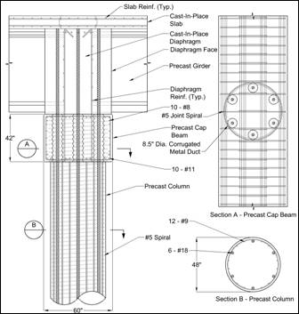
Figure 1 – Details of Full-scale Beam-to-Column Connection
Testing: The anchorage characteristics of large bars were first investigated by conducting full-scale pull-out tests on #10, #14 and #18 bars grouted into corrugated ducts. These tests confirmed that all the bars, including #18 bars, could be fully developed in a length significantly shorter than the 42-inch deep precast cap beam (Steuck et al. 2007, 2009). Those tests combined with earlier work (Raynor et al., 2002; Precast, 2004; Moustafa et al., 1989) showed that the development lengths needed to achieve bar yield and bar fracture were approximately 6db and 10db, respectively. An increase in development length of 50 percent is used to account for cyclic loading. The 50 percent value is conservative and is supported by the cyclic tests in Raynors study. Even with the 50 percent increase in ld to account for cyclic loading, the bars can be developed within the depth of the cap beam to achieve tensile fracture rather than bar or concrete pullout.
Four 40-percent-scale sub-assemblage tests were performed to evaluate the seismic performance of the proposed connection (Pang et al., 2009). The primary study variable was the anchorage length of the longitudinal bars. In two specimens, the reinforcing bars were debonded over 8db near the beam-column interface to reduce the strain concentration.
Each specimen was a scale sub-assemblage of the proposed beam-to-column connection. The full-scale prototype was assumed to be a 4-foot-diameter circular column. Table 1 and Figure 2 show the details of the scaled test specimens. Specimen REF is a scaled model of a typical Washington State cast-in-place bridge column, with 16 #5 bars evenly distributed around the perimeter, giving a longitudinal reinforcement ratio,ρ , of 1.58 percent. The transverse reinforcement consists of a 1/4-inch-diameter spiral spaced at 1-1/4-inches. This specimen provides a baseline for evaluating the performance of the proposed system.
The other three specimens, LB-FB, LB-D1, and LB-D2, represent possible variations of the proposed precast connection. The columns were reinforced longitudinally with six #8 bars that were grouted into 4-inch-diameter corrugated metal ducts in the cap beam and further anchored into the concrete within the diaphragm. This reinforcement provided a longitudinal reinforcement ratio, ρ, of 1.51 percent. In Specimen LB-FB the bars were fully bonded into grouted ducts, whereas in specimens D1 and D2, two methods of local debonding were studied. The local debonding was intended to reduce the strain concentration at the beam-column interface that is caused by the short development lengths. The bars in LB-D1 and LB-D2 were debonded over a length of 8 bar diameters, 8db, into the cap beam using two different methods. LB-D1 was debonded using a 1-inch-diameter Schedule-40 PVC pipe, which was slit longitudinally, fitted tightly around the #8 bar, taped together, and sealed with caulk at the ends. LB-D2 was debonded using a 1-inch-diameter Schedule-30 PVC pipe. That pipe fit more loosely around the bar and was easier to construct, but provided no restraint against bar buckling. The detail was constructed by sliding the pipe over the bar and sealing it with caulk at the ends.
| Specimen | Description | ρ (%) | Longitudinal Reinforcement | fco (ksi) | Paxial (kips) | aaxial (%) |
|---|---|---|---|---|---|---|
| REF | Reference cast-in-place reinforced column | 1.58 | 16- #5 | 6.83 | 240 | 11.2 |
| LB-FB | Precast column with bars fully grouted in corrugated ducts in beam |
1.51 | 6- #8 (12- #3 for spacing) |
8.34 | 212 | 8.1 |
| LB-D1 | LB-FB with bars debonded 8 db in the grouted ducts using Method 1 |
1.51 | 6- #8 (12- #3 for spacing) |
7.69 | 260 | 10.8 |
| LB-D2 | LB-FB with bars debonded 8 db in the grouted ducts using Method 2 |
1.51 | 6- #8 (12- #3 for spacing) |
6.20 | 240 | 12.3 |
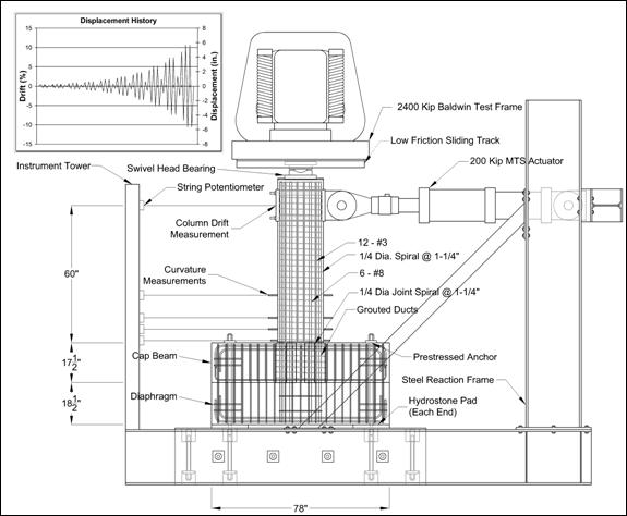
Figure 2 - Test Setup Showing Precast Beam-to-Column Connection
Experimental Results: Each specimen was tested under constant axial load and a cyclic lateral displacement history. The test set up is shown in Figure 2. The selected lateral loading protocol consisted of three cycles at each of a series of increasing displacements.
All four specimens demonstrated nearly identical force-displacement responses and levels of physical damage. Specimens REF, LB-FB, LB-D1, and LB-D2 maintained 80 percent of their peak lateral resistance up to drifts of 5.5, 5.2, 5.7, and 5.8 percent, respectively.
Figure 3 shows the load-deflection curves for each specimen. The four curves are remarkably similar, despite the different specimen construction methods. The slightly different peak loads are mainly attributable to minor differences in the applied axial load. There is a small amount of pinching seen in the curves as the system crosses zero displacement. This pinching occurs because the compressive force is resisted only by the reinforcing bars prior to closing of the cracks in the concrete. It can also be seen that there is little loss in flexural strength until the drift reaches at least 4 percent, despite the increasing amount of damage accumulating in the plastic hinge region.
Figure 3 - Column Moment vs. Drift Plots
The largest contributor to deformation for specimens LB-FB, LB-D1 and LB-D2 was the opening of a large localized crack at the column-to-cap beam interface. Rotations measured over the bottom 1.5 inches of the column accounted for more than 90 percent of the total column displacement. This phenomenon, in which the members behave as essentially rigid bodies, while the connections accommodate deformations, has been successfully used in precast building design and tested in the PRESSS program (Nakaki et al., 1999). In contrast, in Specimen REF, the curvature was more evenly distributed over the bottom 3.5 feet of the column, as is common in cast-in-place systems. In Specimen REF, the crack width at the interface was about the same as the sum of the widths of the flexural cracks above, thus indicating roughly equal contributions to the specimen displacements.
The types and amount of physical damage observed were nearly identical for all specimens, including Specimen REF. Damage consisted of moderate spalling of the concrete cover and crushing of the core concrete over a plastic hinge region about 12 inches long. Spalling initiated at drift levels of 2.0, 2.0, 2.4, and 2.1 percent for specimens REF, LB-FB, LB-D1 and LB-D2, respectively.
At drift levels of 5.6, 5.3, 5.7, and 5.8 percent, respectively, the extreme flexural bars began to buckle, pushing outward on the spiral. The spiral kinked and then fractured shortly after longitudinal bar buckling was first observed. When the buckled bars were next loaded in tension, they straightened and fractured. The finding that buckling in the column occurred at almost the same drift in each specimen was surprising, given that in two specimens the bars were debonded over a length of 8 inches in the cap beam. However, the great majority of the bar deformation occurred in the column, where the detailing was the same in all specimens.
Bars in specimens LB-FB, LB-D1 and LB-D2 fractured at drift levels of 6.5, 7.1, and 7.4 percent, respectively. Bar fracture was brittle with no necking, and occurred approximately 6 inches along the column from the interface with the cap beam, at the peak amplitude of the buckled shape. One bar partially fractured during a load cycle and illustrated the failure process; the inside face of the buckled bar experiences extreme compression strain due to combined compression and bending. When the bar straightens on the next tensile cycle, the inner face undergoes a large strain increment that initiates fracture. This observation and the lack of necking indicate that bar fracture occurs as a consequence of bar buckling and not tensile strain concentration at the interface.
Despite their different capacities for inhibiting buckling, the two types of details, fully bonded and debonded, performed almost identically. This is confirmed by the similarity in their moment-displacement curves shown in Figure 3. The primary reason for the similarity in behavior was that the debonding was located in the cap beam, whereas the buckling deformations occurred in the body of the column, where both specimens were identical. It is felt that debonding is unnecessary, because the grouted bar pulls out a conical wedge of concrete from the duct. Thus, this region behaves similarly to an intentionally debonded bar permitting relief of strain concentration.
Column-to-Footing Connection
Concept: The concept for the foundation is referred to as a socket column and is shown in Figure 4. The construction sequence is as follows. First the column is precast, with a roughened surface in the region that will eventually be embedded in the footing. Then an excavation for the foundation is made. In the bottom of the excavation, a small slab is cast, producing a place to set the column. The column is set, plumbed, leveled and braced. The footing steel is then placed, and the footing is cast.
Figure 4 – Socket Column: Concept
The constructability advantages of the system are:
- It is quick and simple to build,
- The column is easy to transport because no hooked bars project from the bottom,
- There are no potential problems of fit-up of bars in ducts,
- The column detailing can be almost identical to that of a cast in place column, and
- No grouting is needed.
The longitudinal reinforcement in the column is developed at the base by mechanical anchors, rather than the traditional method of bending the bars outwards. Doing so offers the construction advantage that the precast column becomes a large concrete cylinder with no protruding reinforcement, and is therefore simpler and safer to cast and transport. The anchorage method also offers a much more direct transfer of forces between the column and the footing, as demonstrated by the strut-and tie models shown in Figure 5. Figure 5a (excerpted from Xiao et al., 1996) shows the model typically used for bent-out bars. The arrangement requires extensive stirrup steel. Furthermore, the hook on the main bar is ineffective for anchorage because it is facing the wrong way and, in fact, leaves an unreinforced section between the hooks and bottom bars. The model proposed for use with the headed bars (Figure 5b) is, by contrast, simple and provides positive development of the reinforcement. The headed bars thus offer advantages from both constructability and seismic performance viewpoints. This is unusual: more commonly a change that benefits one imposes a disadvantage for the other.
Testing: The major questions associated with the connections seismic performance are related to the transfer of forces from the column to the footing; so the testing focuses on this transfer. The connection must be able to resist the cyclic column moments without significant damage to the footing, and without the column punching through the footing under gravity load. Osanai et al. (1996) tested socket columns for buildings and concluded that, unless special conditions were satisfied, the footing depth should be at least 1.5 times the column diameter. However, the sockets they used were much smaller in plan than a typical spread footing for a bridge, so the HfL tests, which are based on a footing depth/column diameter ratio of 1.0, demonstrated that the connection is strong enough to induce a plastic hinge to form in the column, just above the footing. Achieving this behavior is important, not only because it is required by the AASHTO Specifications (2009), but also because post-earthquake inspection and repair are more expensive for footings than for columns.
Figure 5 - Strut and Tie Models for (a) Bent Out Bars and (b) Headed Bars
Details of the Phase I, 42-percent-scale column-to-footing test specimens are shown in Figure 6. In both, the exterior of the column is roughened where it fits into the footing to improve the transfer of shear stress. The column also extends just below the footing, to be sure that the force transfer at the node at the bottom of the column bars can take place satisfactorily.
(a) Specimen A (Conservative)
(b) Specimen B (Simplified)
Figure 6 - Test Specimens - (a) Conservative and (b) Simplified
Specimen A is the more conservative option. Two footing bars run through a slot under the column in each direction to ensure their direct engagement with the tension steel in the column. Sets of diagonal bars in the horizontal plane are placed in the top and bottom of the footing around the column. Their purpose is to act as "shear friction" steel that will provide the friction forces needed to prevent punching failure along the precast/cast-in-place interface. One set is placed in the top and three stacked sets are placed in the bottom. Ties are included in accordance with the Caltrans recommendations (Caltrans, 2006). The "AASHTO Guide Specifications for LRFD Seismic Bridge Design" (AASHTO, 2009) are based on the Caltrans recommendations, but contain no tie requirements.
Specimen B was designed to determine whether the system could be simplified further. First, in each direction, the two center bars in the bottom mat of the footing steel were moved so they no longer pass under the column, but are placed just outside it. There they are bundled with the existing bars in that location. That placement frees the bottom mat to be placed at any time, thereby improving constructability. Second, the shear friction steel was reduced so that only one set of four bars was used at the top and bottom of the footing. The reasoning was that the bottom mat alone is sufficient, provided that it can be used to provide both flexural strength and shear friction. One set of diagonal bars was retained at the top and bottom to act as "trimming" reinforcement at the corners of the square opening in the footing mat. Last, the tie steel was reduced by 50 percent, on the basis that the Caltrans recommendations appeared to be developed for a system with main bars that are hooked outwards, rather than being anchored by heads. In that case the strut and tie model suggests that tie steel is largely unnecessary.
The testing arrangement for the two specimens is shown in Figure 7, where a compression test machine is used to provide the 159-kip axial load on the columns and a laterally oriented hydraulic actuator applies a horizontal shear load to the tip of the cantilever. The specimens are supported at their edges, but not directly beneath the column. This arrangement prevents the column axial load from bypassing the precast column-to-footing connection and it allows the foundation to partially uplift as the AASHTO design specifications permit. In the photo, hold downs with yellow load cells appear to be restraining the foundation, but these are actually restraints that only engage should the footing begin to rock before developing the full plastic moment at the base of the column. During testing these redundant hold downs were never engaged. The lateral testing protocol comprised three full load reversal cycles at progressively increasing lateral drift levels.
Experimental Results: The two tests described above have been completed. The lateral load, reflected by the moment at the base of the column, as a function of lateral drift is shown in Figure 8. As is evident in the figure, the moment vs. drift plots for the two specimens are virtually identical, and the shape of the plots prior to the beginning of significant strength loss at about 6.8 to 8.7 percent drift indicates good energy dissipation capacity. In fact, the shape of the hysteresis plots is similar to cast-in-place columns; thus the connection performance is emulative of cast-in-place construction. This implies that the same design approach as that used for cast-in-place construction may be used for this type of connection. At drifts over about 7 to 8 percent, longitudinal bar buckling followed by transverse bar fracture leads to rapid loss of stiffness and strength, and this is reflected by the degradation of the curves for higher drift ratios. Longitudinal bar fracture occurred on the cycles to 10 percent drift. The observed behavior was similar to that described earlier for the upper connection of the bent system.
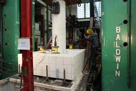
Figure 7 - Loading Arrangement
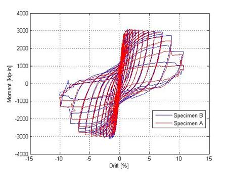
Figure 8 - Column Moment vs Drift for Both Specimens
For these two specimens, spalling of the concrete at the top of the footing, adjacent to the column, began at roughly 1 percent drift. Spalling of the column cover began at roughly 2.4 percent for both columns. The onset of longitudinal bar buckling occurred between 6 and 8 percent drift. For both columns most of the column drift (80 to 90 percent) was attributable to curvatures that occurred in the first four inches of the column above the foundation. The measured curvatures at this location also contained deformations due to strain penetration into the footing.
Following testing, the damage to the columns was observed to be concentrated in the lower eight or so inches of the columns. The post-lateral-testing condition of Specimen A is shown in Figure 9, and the conditions for Specimen B are shown in Figure 10.
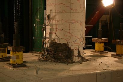
Figure 9 - Specimen A, After Testing
Following lateral testing, Specimen A, in its damaged state, was tested with axially applied load. The purpose of this test was to provide insight into the vertical capacity of the connection between the precast column and the cast-in-place foundation. A total of 850 kips was applied to the column before the column burst at the base. The applied load corresponded to 3.5 times the factored dead and live load that the column was designed to carry. No damage was observed in the footing and no slip was measured between the column and the foundation; thus indicating that the shear-friction connection was more than adequate.
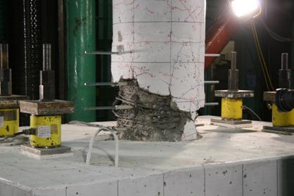
Figure 10 - Specimen B, After Testing
A construction splice was included in the column at 14-inches above the foundation. The grouted splice began at the 14-inch point and extended upward away from the plastic hinging zone. The purpose of this splice was to demonstrate that a grouted splice of the longitudinal bars could be adequately developed to transfer the column forces. This splice is slightly closer to the plastic hinging zone than the AASHTO Guide Specifications (2009) would permit. However, the splices suffered no damage or deterioration during the testing of the columns.
In conclusion, both of the lower connection specimens behaved similarly to cast-in-place specimens, and the connections performed well out to 7 percent drift. There was no relative sliding along the interface between the column and the footing for either the lateral tests or the axial test. The splice in the columns performed well, demonstrating that intermediate column splices between precast pieces can be used. Splices permit partial lengths of columns to be constructed thereby reducing the lifting weights of the precast elements. Finally, no damage, other than minor spalling was observed in the footings, indicating that adequate force transfer capability was achieved, even though the footings were designed to partially uplift. There is no necessity for shear friction bars across the column-to-footing interface, as shown by the adequate performance of Specimen B.
Demonstration Project
The connections described above are designed to be used with a precast bent system that includes precast columns and a precast cap beam. Following the testing of the foundation connection and based on the success of the column-to-cap-beam connection, a demonstration project that uses these connections is planned by the Washington State Department of Transportation. The objective of the project is to demonstrate the constructability of the bent system on an actual bridge project that will be competitively bid and that crosses a major north-south freeway in Washington State, Interstate 5. The demonstration project is a replacement bridge that will be built on an alignment parallel to an existing bridge. The bridge is two-span with tall abutments on the end and a center bent that is located in the median strip. An elevation of the center bent is shown in Figure 11.
The superstructure of the bridge consists of 35-inch-deep, decked-bulb tee prestressed girders that span 88 feet. These are supported by the center bent, which is composed of spread footings, precast column segments, a precast dropped cap beam and a cast-in-place diaphragm. The deck is a 5-inch cast-in-place topping over the decked bulb tees, whose flanges act as stay-in-place forms. The columns used in this project are spliced to permit erection in segments. While the columns of the demonstration project are small enough to be handled in a single lift, the segmental concept will demonstrate the technology for use on projects where the columns are longer and cannot be lifted with a single lift. Additionally, the laboratory specimens for the foundation connection include the same segmental connection, so that the capacity protection aspect of the system was verified in the laboratory tests.
The precast bent system to be used in the demonstration project uses the common Washington State practice of integrating the prestressed girders with the integral full-depth diaphragm over a first-stage cap beam. This system provides longitudinal moment transfer from the bent columns to the superstructure. The precast first-stage cap beam for the demonstration bridge will be built in two pieces that are integrated with a closure pour near the middle of the bent. This is required because the bridge is 84 feet wide, including sidewalks. Ideally, the precast first-stage cap would be built as a single piece element to avoid the time required for splicing segments, but lifting and shipping weight restrictions led to the two-piece solution. This decision would, of course, vary by project.
In support of the demonstration project, the WSDOT Accelerated Bridge Construction Advisory Committee has reviewed intermediate design submittals of the precast bent portion of the demonstration project on a quarterly basis. The committee includes designers from WSDOT, design engineers from local consultants, university professors, bridge contractors and representatives from two precasters. The objective of the review sessions has been to suggest details that improve constructability, structural performance and bid-ability. The resulting details will be finalized in Phase II of the project, however the details tested in the laboratory tests are essentially those that will be used in the field demonstration project.
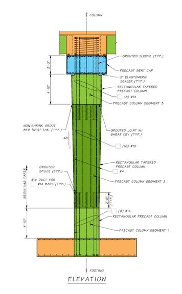
Figure 11 - Demonstration Project Bent Configuration
During the course of the development of the demonstration project design and conduct of laboratory testing, another field application of the precast column-to-spread footing concept was built. The cap beam was still cast-in-place construction; so that feature of this HfL project was not included in this particular application. The precast columns were constructed on-site and placed on mudsills in the same fashion as those for the demonstration project. The use of precast columns was a contractor-proposed change to accelerate the construction schedule. Data on cost savings are not available for this application. However, the schedule for this construction was accelerated about four weeks. Fourteen precast columns on a single pier were constructed using the techniques developed from this HfL project. Thus the constructability of the footing-to-column connection was demonstrated. A photo of the placement of one of these columns is provided in Figure 12.
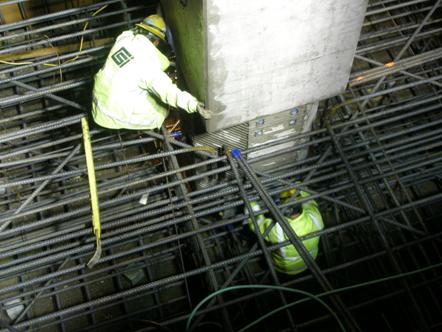
Figure 12 - Placing Precast Column into a Combined Footing for a 14-Column Pier
Along with the demonstration project, sections of the "AASHTO Guide Specifications for LRFD Seismic Bridge Design" that warrant changes in order to accommodate the proposed precast bent system will be identified and modifications will be proposed. This work will occur in Phase II of the project. Also, design examples for the use of precast bent systems with dropped cap beams that support prestressed girder superstructures will be developed in Phase II. These design recommendations will incorporate the findings of the study and allow the knowledge gained from from the study to be used in constructing bridges more rapidly in the future.
Phase II will also include testing of connections that may be used on other bridges similar to, but different to the demonstration project bridge. Currently, the Phase II test specimen design is underway. The specimens include one additional test of a spread footing to determine the minimum thickness of the footing that can successfully transfer the forces required in the joint region. Phase II also includes two additional test specimens that represent the precast bent system foundation connections for use with drilled shaft foundations. The precast column will be attached to the drilled shafts by embedment into the shaft over the column-to-shaft splice zone. The drilled shafts that are being considered are the oversize type of shafts where the shaft diameter is larger than the column diameter. These tests will provide essential information about connections for a commonly used deep foundation.
Conclusions
A precast concrete bridge bent system is presented that is simple, rapid to construct and offers excellent seismic performance. The following conclusions are drawn.
Acknowledgements
Support for this work was provided by the Federal Highway Administrations Highways for LIFE Technology Partnerships Program, by the Washington State Department of Transportation, and by the Valle Foundation at the University of Washington. The findings and conclusions contained herein are those of the authors alone. Additionally, the authors would like to thank Steve Seguirant of Concrete Technology Corporation, Greg Ritke of Graham Construction (formerly with Tri-State Construction) and all the participants in the WSDOT Accelerated Bridge Construction Advisory Committee, as well as Tri-State Construction.
References
"AASHTO Guide Specifications for LRFD Seismic Bridge Design" (2009). AASHTO, Washington DC.
Caltrans (2006). "Seismic Design Criteria Version 1.4." Caltrans, Sacramento, CA.
Getty Center Tram Guideway. http://www.cement.org/transit/tr_cs_gettycenter.asp
Matsumoto, E., Waggoner, M., Sumen, G., Kreger, M., Wood, S., and Breen, J. (2001). "Development of a Precast Bent Cap System," Center for Transportation Research, Research Project 0-1748, University of Texas at Austin.
Moustafa, S., (1989). "Ductile Pullout Connections," Concrete Technology Associates, CTA Bulletin 74B11. Now available from the Precast and Prestressed Concrete Institute, Chicago, IL.
Nakaki, S.D., Stanton, J.F., Sritharan, S. (1999). "Overview of the PRESSS Five Story Precast Test Building," PCI Journal, Volume44, Number 2, March-April 1999, pp 26-39.
Osanai, Y., Watanabe, F. and Okamoto, S. (1996). "Stress Transfer Mechanism of Socket Base Connections with Precast Concrete Columns," ACI Structural Journal, ACI, Chicago. IL. May-June, pp. 266-276.
Pang, J.B.K., Eberhard, M.O., and Stanton, J.F. (2010). "Large-Bar Connection for Precast Bridge Bents in Seismic Regions," Journal of Bridge Engineering, ASCE, Volume 15, Issue 3, May/June, pp 231-239.
Precast and Prestressed Concrete Institute (2004). "PCI Design Handbook," 6th ed. Chicago, IL.
Raynor, D.J., Lehman, D.L. and Stanton, J.F. (2002). "Bond-Slip Response of Reinforcing Bars Grouted in Ducts," ACI Structural Journal. Volume 99, Number 5, Sept. pp 568-576.
Steuck, K., Pang, J., Stanton, J. and Eberhard, M. (2007). "Anchorage of Large Bars in Grouted Ducts," Washington State Transportation Center Report WA-RD 684.1, Seattle, WA.
Steuck, K., Stanton, J.F. and Eberhard, M.O. (2009). "Anchorage of Large-Diameter Reinforcing Bars in Ducts," ACI Structural Journal, July-August, pp 506-513.
Xiao, Y., Priestley, M.J.N., and Seible, F. (1996). "Seismic Assessment and Retrofit of Bridge Column Footings," ACI Structural Journal, ACI, Farmington Hills, MI. Jan-Feb., pp. 79-94.