ARCHIVED: Chapter 5. Hot Mix Asphalt Recycling - Batch Plant (Construction Methods And Equipment)
| << Previous | Contents | Next >> |
Introduction
When properly designed and constructed, recycled hot mix asphalt (HMA) has proved to be at least equal to conventional HMA mixes. Of the various types of recycling options available, hot mix recycling is considered as a very useful and proven method. It can be used to correct mix design problems in existing pavements and make them better, to correct and maintain horizontal geometrics, or as a rehabilitation alternative where curb and bridge clearances are a problem. Hot mix recycling can use the same materials repeatedly, needs minor modification to existing equipment, eliminates disposal problem, and can be done in compliance with existing air pollution control standards.
Hot mix recycling, or hot recycling has been defined as a method by which reclaimed asphalt pavement (RAP) is combined with new aggregate and an asphalt cement or recycling agent to produce hot mix asphalt (HMA). The RAP may be obtained by pavement milling with rotary drum cold milling machine or from a ripping/crushing operation.(1)
Removal Of The Existing Pavement
The two commonly used methods for removal of existing pavement are cold milling, and ripping and crushing. Each of the methods is described in the following sections.
Cold Milling
Of the two available methods for removing an existing pavement, cold milling is the most widely used today. The advent of cold milling has revolutionized the recycling of asphalt pavements. Cold milling has been defined(2) as the method of automatically controlled removal of pavement to a desired depth with specially designed equipment, and restoration of the surface to a specified grade and slope, free of bumps, ruts, and other imperfections. The Asphalt Recycling and Reclaiming Association (ARRA) guideline specification for cold milling requires that the milling machine be power operated, self propelled and self sufficient in power, traction and stability to remove a thickness of HMA surface to a specified depth. The machine should be able to provide a uniform profile and cross slope, and capable of accurately and automatically establishing profile grades within ± 3 mm (within ± 1/8 in) along each edge of the machine by referencing from the existing pavement by means of a ski or matching shoe, or from an independent grade line. A 12.2m (40-ft) ski has been recommended by Brock.(3) The machine should have an automatic system for controlling grade elevation and cross slope. The machine should be equipped with a means to effectively control dust generated by cutting operation.(2) The ARRA has defined five classes of cold milling:
- Class I consists of milling the existing surface to the extent necessary to remove surface irregularities,
- Class II consists of milling the existing surface to a uniform depth as shown in the plans,
- Class III consists of milling the existing surface to a uniform depth and cross slope as shown in the plans and/or special provisions,
- Class IV consists of milling the entire depth of existing surfacing from the underlying base or subgrade,
- Class V consists of milling to a variable depth of the existing surfacing as shown in the plans and/or special provisions.
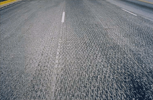
The ARRA recommends that the surface resulting from cold milling operations should have uniform, discontinuous longitudinal striations or other uniform pattern and should not be gauged or torn.(2) Figure 5-1 shows a typical surface resulting from cold milling.(3) Milling should either stay above an interface or cut into the next layer. Milling to interface can result in delamination; shallow and flat depressions; and slabby RAP pieces.
Figure 5-1. A typical surface resulting from cold milling.
Class I and II cold milling are recommended to be measured by the square meter (square yard) for specified thickness or by the square meter-mm (square yard-inch) for the actual square meters (square yards) milled times the mm (in) of depth milled. All other classes of cold milling should be measured by the Mg (ton).(2)
The basis of payment for cold milling should be the contract unit price per square meter (square yard) or per Mg (ton). The bid price should be full compensation for furnishing labor, materials, equipments, tools, and incidentals to complete the work.(2)
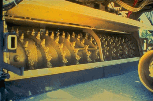
Improvements to the design of the milling teeth have helped in tremendous advancement of cold-milling machines since the seventies. Figure 5-2(4) shows the modern cold milling teeth. Improvement in size and power has lowered cold milling costs significantly. For example, for a 100-mm (4-in) cold milling the present cost can be as low as 30 percent of what it was in the seventies.(3) A front-load machine can pick up conveyor spillage automatically. A built-in broom system can be used to pick up most of the large pieces of the planed material and automatically load onto its drum and back onto the conveyor system. Crushing of RAP is achieved at the same time as milling.
Figure 5-2. Teeth on drum of cold-milling machine.
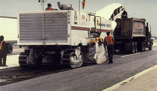
Cold milling machines are available in various sizes and capacities (horse power). A full line of milling machines are available to suit different production requirements. The milling width can be from one meter to a full lane and the milling depth can be from 20 cm to 38 cm (8 to 15 in). Figures 5-3 and 5-4 show a one meter and a full lane cold milling machine, respectively.
Figure 5-3. A one-meter cold milling machine.
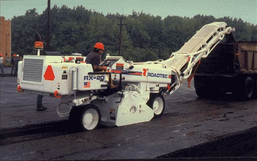
Figure 5-4. A full lane cold milling machine.
Ripping and Crushing
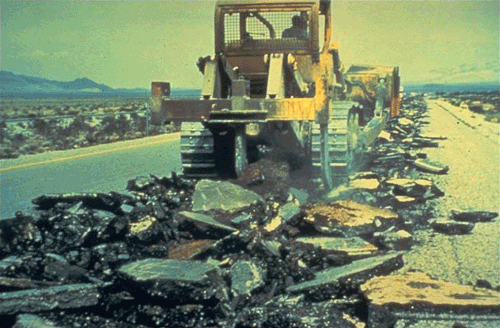
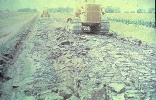
The alternative to cold milling is ripping and crushing operations with earthmoving equipment, scarifiers, grid rollers or rippers (figures 5-5 and 5-6). The material is loaded into trucks and hauled for crushing. The type of ripping equipment to be used depends on the maximum size of the RAP that the crusher can handle. This method is particularly applicable where an existing roadway is to be upgraded for heavier traffic and is of uniform material.(5)
Figure 5-5. Pavement ripping with dozer.
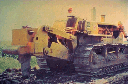
Figure 5-6. Dozer with rear-mounted ripper tooth.
The major advantage of cold milling over ripping and crushing is that crushing of RAP is achieved at the same time and hence results in higher production rate. There is also no heat, and minimal dust is produced. However, unlike ripping and crushing, cold milling produces a greater amount of fines.(4)
Figure 5-7. Ripping and crushing operation.
Crushing And Stockpiling
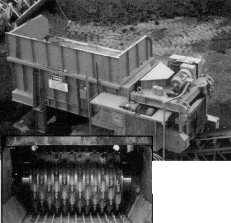
The objective of crushing is to reduce the RAP to the maximum acceptable particle size. One example of such a limit is that at least 95 percent of the RAP pass the 50 mm (2 in) sieve.(6) Cold milling machines can crush the RAP in-place, whereas in the ripping/crushing operation, front-end loaders are generally used to break up the pavement material so that it can be loaded into a truck for crushing at a central plant. The amount of aggregate degradation by cold milling is a function of the aggregate top-size and gradation of the HMA pavement.(4) For crushing in a central plant, different types of crushers are available, for example, compression crushers and impact crushers. A "RAP-breaker" or "lump-breaker" is also used between bin and the belt for size reduction (figure 5-8).
Figure 5-8. RAP breaker.
Impact crushers are most widely used in recycling. This is because compression crushers, such as jaw crushers (figure 5-9) sometimes get plugged up with RAP material. Impact crushers are used both as primary and secondary crushers. In a horizontal impact crusher (figure 5-10), solid breaking bars fixed to a solid rotor crush RAP particles against a striker plate. It can be used as both primary and secondary crusher, and can also be used as a secondary crusher along with a jaw (primary) crusher. In the case of hammermill impact crushers, the breaking bars pivot on a rotor creating a swing-hammer type action (figure 5-11). It can be used both as a primary or as a secondary crusher (with a jaw crusher). Sometimes a combination of jaw and roll crushers (figure 5-12) can be used effectively for sizing RAP material. The jaw crushes the slabs down to a more manageable size, which is then reduced to usable size by a secondary roll crusher. Typically, jaw/roll crushers are used in conjunction with a double deck screen for producing two products for full depth RAP: a fine product (typically < 12.5 mm) and a coarse product (12.5 - 19.0 mm).
Figure 5-9. Jaw crusher.
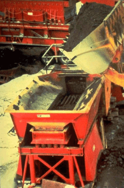
Figure 5-10. Horizontal impact crusher.
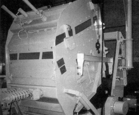
Figure 5-11. Hammermill crusher.
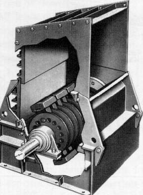
Figure 5-12. Combination crusher.

Both jaw and roll crushers can "pancake" the RAP, especially on warm, humid days. Pancaking is the formation of a flat, dense mass of RAP or crusher surface. It does not affect the quality of the processed material. This is not a problem with horizontal or hammermill crushers.(7)
To produce a homogeneous RAP product, the RAP material is first blended thoroughly with a front end loader or a bulldozer and then crushed to downsize the top stone size in the RAP to one smaller than the top size in the HMA being produced (for example, 16 mm for a 19.5 mm top size mix). This is to ensure that the asphalt aggregate blend is broken as much as possible and there is no oversize material. When a crusher is available at site at all times, smaller quantities are typically crushed, sampled for consistency, and then used. Crushing in smaller quantities makes it easier to sample the crushed product for consistency and keep the crushed product identified. Also, smaller piles can be used quickly before they have a chance to gain moisture from being stored outside, which increases drying costs and limits RAP percentage that can be used.
Care should be taken to avoid removing the fines from the reclaimed HMA pavement since the fines retain much of the aged asphalt that is to be recycled. The crusher should not also produce an increase in fine size material or new fractured faces which can require more virgin binder material and hence increase in cost.(6)
RAP from different sources and containing different asphalt content and aggregates with different gradations should be stockpiled separately. RAP can be stockpiled either before or after processing and a front end loader or a radial stacker can be used for the purpose. Figure 5-13(4) shows a radial stacker used for stockpiling RAP. The two major problems associated with stockpiling are consolidation and moisture retention.
Figure 5-13. Radial stackers for building up RAP stockpiles.
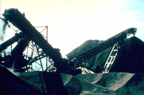
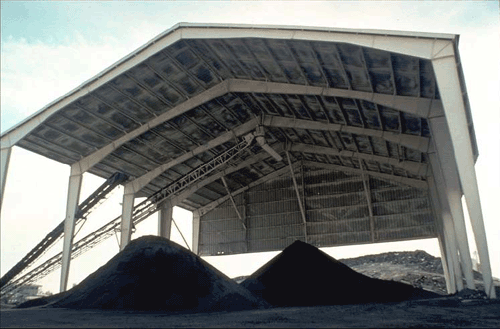
In the past, it was believed that low, horizontal stockpiles are better than high and conical stockpiles which can result in re-agglomeration of RAP. However, experience has proven that actually large, conical stockpiles are better(7) and that RAP does not recompact in large piles. Actually, there is a tendency to form a crust over the 20-25cm (8-10 in) of pile depth. This crust can be easily broken by a front end loader. Also, the crust tends to shed water and prevent the rest of the pile from recompacting. In the case of a low, horizontal stockpile also this 20-25 cm (8-10 in) crust is present. However, it is more difficult for the front-end loader operators to work around a low pile. The stockpile should be built on a solid surface to prevent contamination or compaction of the underlying surface. The finer particles in the processed RAP material tend to absorb and retain moisture. This increases the moisture content of the material and hence the energy required to drive it off during production. The heat primarily comes from the heated uncoated aggregates, and since there is a limit up to which the aggregates can be heated, either the amount of RAP or the production rate has to be sacrificed if there is an increase in moisture content.(4) Figure 5-14 shows a plot of moisture content versus temperature required for drying to produce recycled HMA. It shows that there is a significant increase in drying temperature per degree increase in moisture content. An increase in moisture content of the RAP by even 0.5 percent will hinder HMA production capabilities seriously.(5) Hence, proper drainage of the stockpile should be provided. Tall conical stockpiles provide better drainage compared to low, flat stockpiles. Depending on the annual moisture level in the region, use of protective coverings such as tarps and even structures should be also be evaluated.(8) Figure 5-15(7) shows a shed used for storing RAP.
Figure 5-14. Plot of moisture content vs. drying temperature.
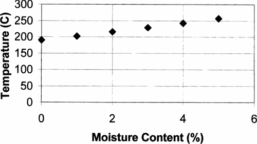
Figure 5-15. Structure for protecting and minimizing moisture in RAP or aggregates.
Modifications To Batch Plant For Recycling
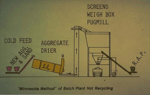
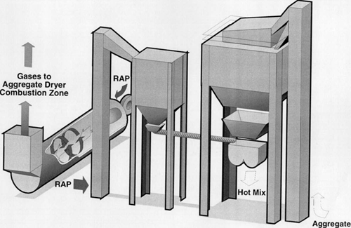
Modifications are required in the batch plant to recycle RAP since attempts to introduce RAP directly with the virgin aggregates result in excessive smoke and material build-up problems in the dryer, hot elevator and screen tower.(4) The most widely used method for batch plant hot-mix recycling is the "Maplewood Method."(5) Other recycling processes used in batch plant are described later. Figure 5-16 shows the schematic of the "Maplewood Method." Even though variations exist, basically a separate cold feed bin introduces the RAP into the weigh hopper or the pugmill by a chute and belt conveyor. There the RAP is joined by the virgin material coming from the cold feed bins through the dryer and the screen decks. The temperature to which the virgin aggregates are superheated depend on the properties of the RAP material.
Figure 5-16. Maplewood method of batch plant hot recycling.
Exhaust capacity of pugmill or weigh hopper is important since a significant amount of steam is generated when the dry virgin aggregates come in contact with relatively moist and cold RAP. The steam produced can either be exhausted by the RAP charging chute or an exhaust duct fitted to the pugmill or weigh hopper. Many producers vent their pugmills or weigh hoppers into the drier exhaust stream. This is done by enclosing the pugmill and ducting into the exhaust steam equipment.(5)
Depending on the method used to convey the RAP to the weigh hopper or the pugmill, different modifications are needed to recycle HMA. The following modifications are needed.(9)
Aggregate Dryer
Since a relatively lesser amount of virgin aggregate is superheated in HMA recycling, some modifications are needed in the dryer. An adequate veil must be maintained in front of the burner flame. A cooling period at the end of each production period may be necessary to prevent warping of the drum at high temperatures.
Dryer Exhaust System
Modification of this system is necessary to prevent damage of baghouse collectors from the high temperature exhaust gases which result from superheating of virgin aggregates. Several methods may be adopted to lower the temperature of the exhaust gas. These include redesign of dryer flights, use of longer duct work, addition of cooling air or water spray into the exhaust system.
Screen Deck
To prevent excessive increase in temperature, special lubricants may have to be used in the screen bearings located inside the duct housing.
Hot Bins
Depending on the size of the bin and the material storage time, the outside of the hot bins may have to be insulated to prevent drops in the superheated aggregate temperature.
Binder Feeder
The asphalt binder feeder system should be modified to include a recycling agent discharge system, either into the asphalt weigh bucket or the pugmill. However, this is required only if a recycling agent is used in the process.
RAP Cold Feed Bin
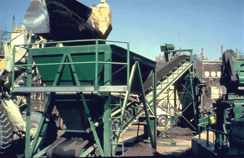
To avoid accumulation and bridging of the RAP material, the cold feed bin should be relatively small with steep sides and a large discharge opening (figure 5-17).
Figure 5-17. RAP cold feed bin.
RAP Feeder and Conveying System
To ensure continuous operation, the feeding and the conveying systems should have sufficient capacity to deliver RAP into the weighing hopper without any delay. Also, if a special surge bin is not provided above the hopper, the conveyor system should be equipped with a heavy-duty motor to ensure continuous starting and stopping.
Entrance Chute to the Weighing Hopper
The entrance chute to the weighing hopper should be as steep as possible, of constant width and provided with a counterweight draft gate to prevent the escape of dust when the RAP is introduced. The entrance chute should be capable of introducing the material at the center of the weighing hopper.
Venting for Weighing Hopper and Pugmill
Adequate venting for the weighing hopper and the pugmill should be provided to prevent build up of moisture and dust emissions during mixing operations. The dust entrainment by the steam from the RAP can be prevented by reducing the dry-mixing time also. The amount of steam produced depends on the moisture content of RAP and the amount of RAP per batch of mix. Higher the amount of moisture, and higher the amount of RAP per batch, higher is the amount of steam produced.
Storage Silos
Storage silos may be used to store the hot mix after it leaves the pugmill, so that it gets sufficient time to attain temperature equilibrium throughout the mix.(6) This is because the transfer of heat from the superheated aggregate to the relatively cold RAP may not be completed in the relatively short mixing time, especially since in many cases the mixing times are not altered from normal mixing times used for virgin HMA mixes.
Recycling Processes In Batch Plant
In the recycling process the virgin aggregates must be superheated to a certain temperature to transfer heat and dry the RAP material. Table 5-1(7) shows the temperatures to which the virgin aggregates must be heated for different discharge temperatures of recycled mix and RAP moisture content.
| Reclaimed Material | Moisture Content (Percent) | Recycled Mix Discharge Temperature, °C(°F) | |||
|---|---|---|---|---|---|
| 104°C (220°F) | 115°C (240°F) | 167°C (260°F) | 138°C (280°F) | ||
| A. Ratio: 10% RAP / 90% Aggregate | 0 | 121(250) | 138(280) | 152(305) | 163(325) |
| 1 | 127(260) | 143(290) | 154(310) | 168(335) | |
| 2 | 132(270) | 146(295) | 157(315) | 171(340) | |
| 3 | 138(280) | 149(300) | 163(325) | 174(345) | |
| 4 | 141(285) | 152(305) | 166(330) | 177(350) | |
| 5 | 193(290) | 157(315) | 168(335) | 182(360) | |
| B. Ratio: 20% RAP / 80% Aggregate | 0 | 138(280) | 154(310) | 168(335) | 182(360) |
| 1 | 146(295) | 160(320) | 177(350) | 191(375) | |
| 2 | 154(310) | 168(335) | 182(360) | 196(385) | |
| 3 | 163(325) | 177(350) | 191(375) | 204(400) | |
| 4 | 171(340) | 185(365) | 199(390) | 213(415) | |
| 5 | 179(355) | 193(380) | 207(405) | 221(430) | |
| C. Ratio: 30% RAP / 70% Aggregate | 0 | 157(315) | 179(345) | 191(375) | 207(405) |
| 1 | 168(335) | 185(365) | 202(395) | 218(425) | |
| 2 | 182(360) | 199(390) | 216(420) | 232(450) | |
| 3 | 196(385) | 213(415) | 229(445) | 246(475) | |
| 4 | 210(410) | 227(440) | 243(470) | 260(500) | |
| 5 | 224(435) | 241(465) | 257(495) | 274(525) | |
| D. Ratio: 40% RAP / 60% Aggregate | 0 | 179(355) | 199(390) | 218(425) | 138(460) |
| 1 | 199(390) | 218(425) | 238(460) | 257(495) | |
| 2 | 218(425) | 238(460) | 257(495) | 277(530) | |
| 3 | 243(470) | 260(500) | 279(535) | 299(570) | |
| 4 | 260(500) | 279(535) | 299(570) | 321(610) | |
| 5 | 285(545) | 302(575) | 321(610) | 341(645) | |
| E. Ratio: 50% RAP / 50% Aggregate | 0 | 210(410) | 235(455) | 257(495) | 282(540) |
| 1 | 240(465) | 268(515) | 288(550) | 310(590) | |
| 2 | 271(520) | 293(560) | 318(605) | 243(650) | |
| 3 | 302(575) | 327(620) | 349(660) | 374(705) | |
| 4 | 338(640) | 360(680) | 379(715) | 409(760) | |
| 5 | 365(690) | 390(735) | 413(775) | 438(820) | |
Note:
- 11°C (20°F) loss between dryer and pugmill assumed in these calculations.
The different methods of batch plant operation for recycling are given below.(3,7)
Method 1. The method is illustrated in figure 5-18. The superheated virgin aggregates and the cold RAP are introduced into the boot of the hot elevator. The mixed material is screened and stored in hot bins. The scavenger system in the batch tower pulls off the water evaporated from the RAP. There is no resulting emission problem in this operation.
However, unless the screen cloth in the bottom deck exceeds 5 to 6 mm (3/16 to 1/4 in), relatively low percentage of RAP may be used in this process without blinding the screens (especially 6.4 mm screen). It is necessary to avoid excessive moisture in RAP to prevent blinding of the screens.
Figure 5-18. RAP into batch plant hot elevator.
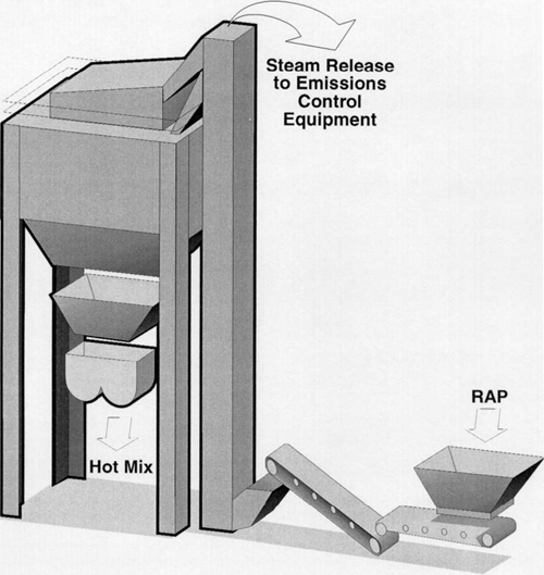
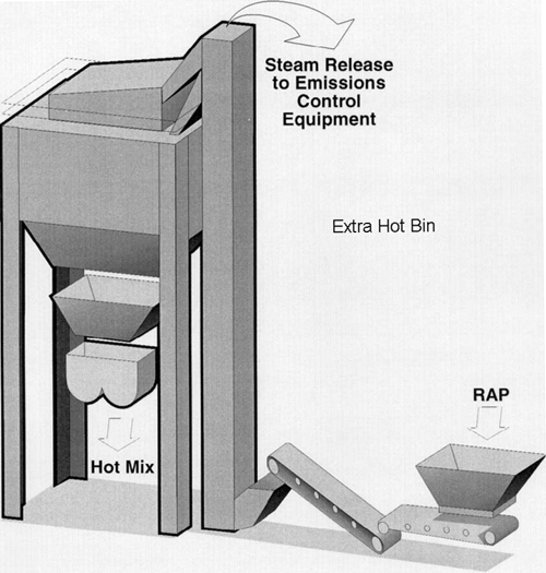
Method 2. The batch tower is required to have a fifth hot bin in this method. The procedure is shown in figure 5-19. The virgin aggregate is screened, superheated and then deposited at the boot of the hot elevator along with the cold RAP. The blended material is introduced in the fifth hot bin without going through the screens in the tower. This method allows the use of up to 40 percent RAP and also switching from RAP mixes to virgin mixes without emptying the hot bins since the materials in the hot bin are not superheated. (Note that the figures for Method 1 and 2 are the same. This is because the procedures are similar, except for the fifth bin in Method 2).
Figure 5-19. Batch tower fifth hot bin for RAP.
Method 3. In this so called "Maplewood Method," which is most commonly used (figure 5-20), the cold pre-screened RAP is delivered directly into the weigh hopper of the batch tower along with the superheated virgin aggregate from a hot bin. The RAP is delivered from a RAP bin through an inclined conveyor having automatic plant controls. In this process, the RAP material may be added after material from bin 1 is added to the weigh hopper and before the material from bins 2, 3 and 4 are added to the weigh hopper. In this way the RAP is sandwiched between the hot virgin aggregates and gets more time to heat up. A mild explosion results from instant evaporation of the RAP moisture when the unmixed aggregates are discharged into the pugmill.
Figure 5-20. RAP directly into weigh hopper.
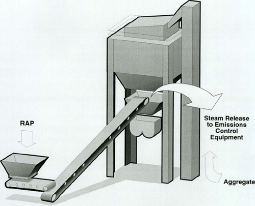
To scavenge the mixer during the steam generation a baghouse with considerable capacity is required unless the dump time of the weigh hopper is increased. Another less practical method is to build a large chamber behind the plant. The chamber serves as a surge container into which the exploding steam can escape.
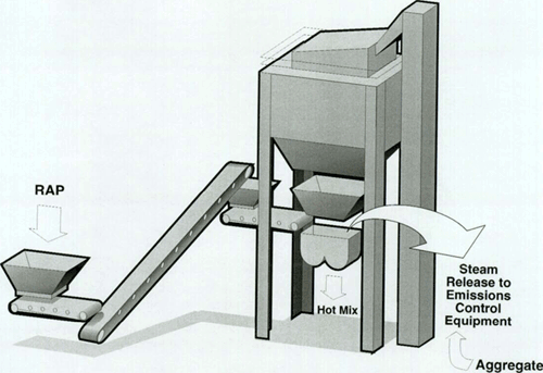
Method 4. This is a new control feed system (figure 5-21) in which the RAP is fed onto a third scale to obtain a set amount of RAP. After the RAP is weighed, it is dropped into a bin with a feeder. The feeder introduces the RAP into the pugmill over a 20 to 30 seconds period. This method allows relatively more control of the generated steam by slowing down the batch cycle.
Figure 5-21. Controlled feed to weigh hopper.
Method 5. This expensive system (figure 5-22) preheats the RAP in a separate dryer before mixing it with the virgin aggregates. Heated RAP materials are then conveyed to a separate, heated storage bin which has its own weigh hopper on a typical batching tower. RAP materials are weighed as a separate ingredient, then conveyed to the pugmill for production of recycled mix. Variations in moisture content and oxygen available from the RAP heater make system control difficult. However, 35 to 40 percent RAP have been used with this method.
Figure 5-22. RAP heater for batch plant.
Amount of RAP Used
Factors controlling the percentage of RAP are the temperature to which new aggregates must be heated, moisture content of RAP, temperature of the RAP in stockpile, desired recycled HMA mix temperature, HMA production rate, exhaust capacity of pugmill or weigh hopper, and the percentage of material passing the 0.075 mm screen in the RAP.(5) According to the Asphalt Recycling and Reclaiming Association, the practical limit for hot mix recycling in a batch plant is 20 percent RAP, although up to 40 percent RAP can be used. However, as high as 50 percent RAP has been used if the moisture content of the RAP is minimal and the RAP is fed to the plant at the ambient temperature. Generally, 30 to 35 percent RAP is considered to be the practical limit with 10 to 20 percent RAP being a typical range.
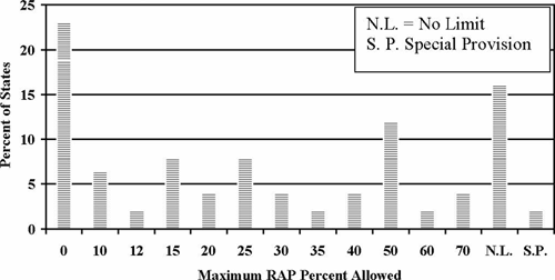
Figures 5-23 through 5-25 show plots of RAP percentage allowed in base, binder and surface courses.(10) In base course, the percentage of RAP allowed ranges from 15 to 100, with a large number of states (27.1 percent) allowing 50 percent. A substantial number of states (22.9 percent) have no limit on the amount of RAP that can be used. For binder course the percentages range from 15 to 100. Approximately equal number of states (25.1 and 20.8 percent) allow 50 percent and unlimited amount respectively. A small number of states (2.1 percent) do not allow RAP in batch plant for binder course. For surface course, the allowable percentage ranges from none to 100. A significant percent of states (22.9 percent) do not allow any RAP, whereas 16.6 percent of the states allow unlimited RAP. Some states have special provisions for allowing RAP in the surface mixes.
Figure 5-23. Maximum RAP percent allowed for batch plant mix in base course.
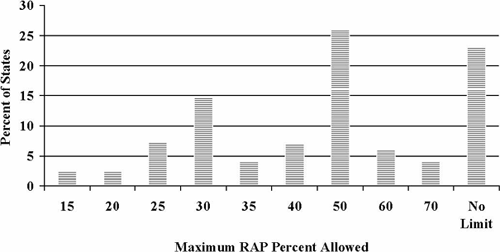
Figure 5-24. Maximum RAP percent allowed for batch plant mix in binder course.
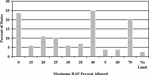
Figure 5-25. Maximum RAP percent allowed for batch plant mix in surface course.
Summary
Hot mix recycling has been proven to be a viable rehabilitation technique. When designed and constructed properly, hot mix recycled pavements have performed similar to or better than conventional HMA pavements. The method of hot mix recycling includes removal of existing HMA pavement, crushing, stockpiling of RAP, mixing, lay down, and compaction. Except for lay down and compaction, which are similar to conventional hot mix construction, the other processes require some modification to existing plants or some new equipments. The most commonly used method of hot recycling in batch plants is the heat transfer method. The virgin aggregates are superheated to a certain temperature to transfer heat and dry the RAP material. Proper care should be taken in crushing to smaller sizes, and stockpiling the RAP to prevent contamination, consolidation or moisture retention. Production of recycled hot mix must be made under strict quality control to ensure satisfactory performance of the mix.
References
- An Overview of Recycling and Reclamation Methods for Asphalt Pavement Rehabilitation, Asphalt Recycling and Reclaiming Association, Annapolis, MD, 1992.
- Guideline Specifications for Cold Planing, Asphalt Recycling and Reclaiming Association, Annapolis, MD, 1992.
- J.D. Brock. Milling and Recycling, Technical Paper T-127. Astec Industries, Chattanooga, TN, April, 1994.
- Pavement Recycling Guidelines for Local Governments - Reference Manual, Report No. FHWA-TS-87-230, FHWA, U.S. Department of Transportation, Washington, DC, 1987.
- Proven Guidelines for Hot-Mix Recycling, Asphalt Recycling and Reclaiming Association, Annapolis, MD, 1986.
- Asphalt Hot-Mix Recycling, The Asphalt Institute Manual Series No. 20 (MS-20), Second Edition, 1986.
- Recycling Hot Mix Asphalt Pavements, Information Series 123, National Asphalt Pavement Association, 1996.
- D.A. Bernard and J.A. Epps. Pavement Recycling, Prepared for Japan Highway Public Corporation, 1982.
- V.P. Servas. Asphalt Recycling - The State of the Art, 1980, Report prepared under the joint sponsorship of the United Kingdom Department of Transport, Colas (UK) Ltd. and Shell International Petroleum Co. Ltd., London, 1980.
- L. Flynn. "Surface Courses in Montana Now May Contain 25% RAP." Roads and Bridges, October, 1995.
| << Previous | Contents | Next >> |

