U.S. Department of Transportation
Federal Highway Administration
1200 New Jersey Avenue, SE
Washington, DC 20590
202-366-4000
Federal Highway Administration Research and Technology
Coordinating, Developing, and Delivering Highway Transportation Innovations
 |
| This report is an archived publication and may contain dated technical, contact, and link information |
|
Publication Number:
FHWA-RD-98-139
|
Prior to the establishment of this research program, foundation
engineering guidelines were mostly empirical and barely sufficient for most highway applications.
The result was an inability to accurately predict the performance of foundation systems, which, in
turn, led to very conservative design procedures as well as an occasional foundation failure.
A comprehensive research plan was initiated in the late 1970's to develop improved design
and construction guidelines for building safer and more cost-effective bridge foundations.
Engineering improvements were expected to reduce the cost of these foundations and stretch
the highway dollar to buy more bridges that will last longer.
An analysis of future needs for highway bridge foundations was completed under this project to
provide essential planning information for conducting effective research on bridge foundations.
Estimates of the number of new bridges to be constructed and those that would need to be replaced
or rehabilitated during the remainder of this century were made in 5-year increments using data from
FHWA bridge inventory and inspection reports. An analysis of FHWA foundation management review reports
was also made to determine typical foundation types used in each State and likely to be used on future
construction. The analysis was also supplemented with personal interviews with selected State and
FHWA bridge engineers from various regions of the country (1).
Results of these analyses indicated that more than 100,000 bridges would be constructed, replaced,
or rehabilitated in the United States during the last 20 years of this century. Approximately
20,000 new bridges would be built and more than 15,000 existing bridges had deficient foundations.
Many of the satisfactory foundations would also have to be replaced because of retrofit problems
caused by replacing the superstructure. A large number of reusable foundations required special
design and construction procedures that needed to be developed. It was also noted that more
than two-thirds of these bridges were likely to be supported on piles, one-fourth of them on
spread footings, and the rest of them on drilled shafts or other types of foundations (1).
2.1 Background
Because the safety and cost-effectiveness of bridge foundation
systems is of major importance, an appropriate research program to develop better design tools
has long been advocated by both structural and geotechnical engineers. Foundations represent
about 30 percent of the cost of highway bridges in typical applications; however, this cost can
be even higher where bridges are built near or on difficult soil conditions. The total annual
expenditure of public funds for bridge construction is conservatively estimated to be more than
$2 billion, which means that foundations are costing more than half a billion dollars per year.
Because the predominant type of foundation system used in the highway industry is piles, the
first priority for this project was the efficient design of piles. Research was also needed
to develop new concepts for reducing our excessive reliance on pile foundations. In
situations where deep foundations are required, the overall cost can be significantly
reduced by using smaller piles and fewer of them as a result of design economies developed
under this research project.
The indiscriminate use of pile foundations was partly due to a lack of confidence in the safety
and dependability of drilled shafts and shallow foundations, but mainly due to unreasonably
restrictive deformation and movement constraints. Therefore, the establishment of rational
criteria for tolerable movements was a necessary first step toward improving foundation
design (see section 2.5).
Assuming a 25 percent reduction in the use of piles can be accomplished by substituting
cheaper drilled shaft or shallow foundation units, the use of piles will still account
for much more than half the foundation systems used for highway structures. Therefore,
the continued investigation of pile-soil behavior will provide cost-effective improvements.
One of the most incongruous aspects of foundation design is the overwhelming use of a
system (friction piles) that is the least understood.
2.2 Objectives
The overall project objective was to develop improved foundation design and construction methods for highway bridges. This objective was approached through efforts directed toward accomplishment of the following four separate, but related goals:
2.3 Scope
Research efforts in this project were directed toward developing new predictive techniques for foundation design, better criteria for tolerable movements, and permissible stress levels in piles and drilled shafts, as well as improved construction control techniques. Each component of the total foundation system was studied individually and each total system was evaluated as a whole. The behavior of the foundation systems was also examined under both working and ultimate stresses.
2.4 Project Description
The major research efforts were organized into five tasks:
The Foundations Project was the "flagship" project of the FHWA Geotechnology Research Program. It could and probably will be a separate report by itself; in fact, each of the five main tasks could also be a separate report. The following six sections of this chapter provide a summary of the major highlights of this project.
2.5 Structural Consequences of Foundation Movements
During the development of the FHWA research project on
foundations, it was determined that one of the major reasons that bridge foundations
were over-designed had its roots in the lack of rational criteria for tolerable
movements of the superstructure. The American Association of State Highway and
Transportation Officials (AASHTO) design code at that time was relatively silent
in this area, and basically promoted a "zero" settlement design procedure.
This resulted in a very high cost of obtaining little or no settlement in terms of
utilizing the soil load-carrying capacity because it is almost impossible to achieve
this objective. The cost was often extremely high and very wasteful.
Foundation movements under highway bridges (figures 1 and 2) had occasionally been
predicted and measured; however, there had been very few investigations of the effect
these movements would have on the safety and serviceability of the bridge structure.
As a result, tolerable foundation movement had not been established beyond the conceptual
stage, and much controversy among engineers was prevalent.
In addition to the disagreement on the definition of tolerable settlement, there was
also disagreement on the accuracy of settlement predictions. As a result, many
engineers still prescribed strict settlement constraints to guard against erroneous
predictions. In many cases, the precautions were unrealistic and underestimated
the accuracy of the prediction techniques, which are normally accurate within 10
to 20 percent on average and are rarely more than 50 percent off the measured value.
It was noted in earlier studies that using piles did not guarantee that there would
be little or no settlement, unless the piles were founded on hard rock. The nature
of load transfer from the pile to the soil surrounding (side friction) and beneath
the pile (tip bearing) requires some movement of the pile to mobilize the load-bearing
capacity of the soil material. The relative movement required to mobilize maximum
frictional strength is approximately 6.35 mm (0.25 in), while the displacement
required to mobilize the soil's shear strength under the pile tip is usually
much larger than that value. If the allowable settlement is restricted to a smaller
value than what is required to mobilize tip resistance, the load-carrying capacity
of the pile is artificially reduced to the level of side friction support. The
support capacity available at the pile tip then becomes an additional safety factor.
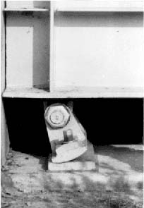
FIGURE 2. Bridge girder jammed against abutment and excessive rocker tilt.
Overly restrictive settlement constraints can reduce
significantly the supporting capacity of friction piles. To comply with the prevalent
requirements of zero or near zero settlement, the foundation engineer must reinforce
his or her design by adding more piles, using longer piles, or increasing the diameter
of the piles. The conservative effect of this design philosophy is evident by examining
any load-settlement curve from a pile load test. A slight increase in the allowable
settlement value can impact significantly the allowable design load for a pile foundation,
especially within the straight line portion of the curve.
A relaxation of the stringent movement criteria was also expected to impact significantly
the use of spread footings, whose major drawback is the risk of some settlement. Because
the economic breakpoint in the normal design procedure for spread footings centers around
25 mm (1 in) of settlement, the majority of bridge engineers were reluctant to use
this less expensive method of foundation support. As a result, the highway industry has
been accused of having numerous "buried treasures" beneath bridge abutments
and piers, because piles were used instead of spread footings or because more and/or
larger piles were used than necessary.
Research performed under this project indicated that bridge structures can withstand a
reasonable amount of settlement, and the amount varies according to the span arrangement
(simple versus continuous) and length of span as well as other design variables.
This indicates that the AASHTO blanket criterion approach was inappropriate and the
zero settlement design approach was too conservative.
2.5.1 Preliminary Studies - Prior
to the initiation of a comprehensive research study by FHWA, a series of smaller studies
that were conducted in Ohio, Washington, Connecticut, Canada, and by FHWA staff were
evaluated to help develop a detailed research plan. Studies done for the building
industry were also included in the evaluation. A study of the measured movement
data and corresponding damage assessments were very enlightening, but insufficient
to establish rational tolerable movement guidelines. It was also noted that the
building codes in many major U.S. cities actually permitted larger settlements
than AASHTO bridge specifications, even though building elements, such as glass
doors and windows, elevator shafts, utility lines, and brittle wall panels, are
more sensitive to foundation settlement than bridge elements.
Although no well defined set of criteria was generally agreed upon, all of the
researchers agreed that the development of a rational set of tolerable movement
criteria for bridges was a high priority research need. Everyone then turned to
FHWA's Office of Research to conduct a major effort to solve this problem.
2.5.2 FHWA Tolerable Movement Study -
A comprehensive analysis of the data from the earlier studies that evaluated field
measurement surveys was conducted as part of an overall analytical investigation of
the effect of different magnitudes of settlement on the potential level of distress
produced in a wide variety of steel and concrete bridge structures of different span
lengths and stiffnesses. A total of 314 bridges in the United States and Canada was
analyzed to determine if the measured foundation movements and corresponding damage
assessments could yield sufficient insight toward the development of rational
criteria for tolerance to movement. The data by themselves proved to be
insufficient, but when combined with the structural analysis studies, and
an appraisal of existing design specifications and practice, a rational set
of criteria was developed.
The researchers determined that functional distress is more difficult to assess
than structural distress because of its subjectivity. Functional distress is
defined under this study as damage to the architectural elements or a reduction
in ride quality. Architectural damage is less severe than structural damage that
affects the integrity of a main supporting element of the bridge; however,
architectural damage is usually more visible and causes an annoying or insecure
feeling on the part of the motorist. It is also referred to as "cosmetic
damage" and includes cracking or misalignment of bridge railings, curbs,
decks, abutment wing walls, and damage to light poles and utility lines. The
deterioration of ride quality involves the "bump" at the end of the
bridge and other roadway unevenness associated with bridge foundation settlement.
The specific results of this study have shown that, depending on type of spans,
length and stiffness of spans, and the type of construction material, many highway
bridges can tolerate significant magnitudes of total and differential vertical
settlement without becoming seriously over-stressed, sustaining serious structural
damage, or suffering impaired riding quality. In particular, it was found that a
longitudinal angular distortion (differential settlement/span length) of 0.004 would
most likely be tolerable for continuous bridges of both steel and concrete, while a
value of angular distortion of 0.005 would be a more suitable limit for simply
supported bridges.
For continuous steel bridges, differential settlements of 25 mm (1 in) or more
would be intolerable for span lengths up to 15.2 m (50 ft) because of the significant
increase in stresses caused by these settlements. However, for span lengths between
30.5 and 61.0 m (100 and 200 ft), the stress increases caused by differential
settlements up to 76 mm (3 in) were quite modest, and for spans longer than 61.0 m
(200 ft), the stress increases caused by 76 mm (3 in) differential settlements were
negligible.
A basic design procedure was developed that permits a systems approach for designing the
superstructure and the foundation system. This design procedure incorporates the
tolerable movement guidelines that are based on strength and serviceability criteria
which, in turn, are based on limiting longitudinal angular distortion, horizontal
movements of abutments, and deck cracking (2,3).
2.5.3 Publications and Implementation Items - Research and development activities for the establishment of tolerable movement criteria were very successful. The FHWA R& D reports documented the efforts that were made to develop the rational criteria and presented detailed recommendations on how the new criteria should be used in typical bridge and foundation engineering scenarios. A technology sharing report was developed to help practitioners implement the new criteria in standard design situations (4). Workshops and presentations were also held to aid the implementation process. A new article was developed for the AASHTO Bridge Specifications (see chapter 7).
2.6 Pile Foundations
The first difficult problem confronting the designer
of a foundation is to establish whether or not the site conditions are such that piles
should be used. The most common case is that in which the upper soil strata are too
compressible or generally too weak to support heavy vertical reactions transmitted by
the superstructure. In this instance, piles serve as extensions of columns or piers
to carry the loads to a deeper, more rigid stratum such as rock (point-bearing piles).
If such a rigid stratum does not exist within a reasonable depth, the loads must be
gradually transferred by friction along the pile shaft. Scour and the relative inability
of spread footings to transfer inclined, horizontal, or uplift forces and overturning
moments also require the use of piles in many instances.
Another problem facing the pile designer is choosing from among the 100 or more
different kinds of piles. There are many variations in materials, configurations,
and installation techniques. Guidelines for selecting the best pile for various
situations can be found in one or more of FHWA's guidance manuals (5, 6, 7) and
the general literature.
After a particular kind of pile has been selected for use, the designer then must
determine the number, length, and size of the piles required. Simple guidelines
were not available at the start of this research program to design and analyze
piles for the various situations that can occur in bridge foundations; however,
improved pile design guides are now available in various FHWA references listed
at the end of this report. The ultimate load that can be supported by a certain
kind of pile depends on the strength of the soil and/or pile material. Usually
the ultimate load is determined by soil failure; however, the pile itself may fail
if forced to penetrate difficult site conditions such as dense soil or rock.
Calculating the ultimate load on the basis of soil failure is one of the most
difficult problems confronting the foundation designer. Because available
theories for determining the ultimate load of a pile and a group of piles
were not accurate enough to provide economical foundation designs, research
was conducted to define the complex mechanics of load transfer between pile
and soil and among the various piles within a pile group. Load transfer in
piles and pile groups was measured in the laboratory and field to develop
and refine analytical models of the pile behavior process to provide more
economical design procedures.
Assuming the pile material is not over-stressed, the ultimate load capacity
of a pile is equal to the sum of two major soil components — point
resistance and side friction. The amount of support contributed by each
component varies according to the soil properties and pile dimensions.
These resistances can be calculated through mathematical relationships;
however, the required input data are difficult and expensive to obtain.
As a result, less expensive index testing usually is performed to obtain
approximate values for estimating the resistances.
Pile capacity usually is predicted using static and dynamic analysis procedures.
On large, expensive structures, pile load tests often are used to verify the
design loads. Recently completed FHWA experimental studies of instrumented
piles load tested to failure have increased our understanding of load-transfer
behavior of single piles and pile groups; however, more tests are needed to
confirm the new prediction methods.
A mathematical model of pile group behavior was deemed to be a valuable analytical
tool that systematically can convey engineering experiences from one site to
another. Several mathematical models had been developed, including one by FHWA;
however, none had been validated adequately because of the lack of precise field
data on pile group behavior. This was especially true of new foundation design
methods based on finite element analysis. To date FHWA has performed most, if
not all, of the pile group load tests to failure. These results have been used
to validate and refine the FHWA pile group design model called PILGP (8).
2.6.1 Areas of Emphasis - Because of the high reliance on driven piles, a large portion of FHWA funds for foundation research was directed at improved design and construction procedures for driven piling. FHWA pile research was divided into the following three major areas of emphasis:
2.6.2 Single Piles in Clay - Field
load tests on single piles in soft clays have provided experimental data to evaluate
a promising pile capacity predictive technique based on the general effective stress
method. The effective stress method for predicting pile capacity was validated and
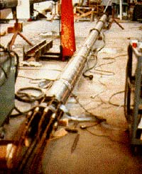
its accuracy and general applicability were improved. Figure 3 shows a full-scale
pipe pile being instrumented in the laboratory prior to field installation.
The accuracy of the method was limited by the assumptions made to describe the
changes in effective stress between pile driving and subsequent loading. Major
uncertainties arise in attempted modeling of the effective stresses after the
disturbed soil has reconsolidated. Current analysis techniques were considered
applicable to full displacement piles driven into normally consolidated
clays (9).
|
|
|
|
FIGURE 3. Lab instrumentation of a pipe |
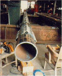
FIGURE 4. Field instrumentation of a pipe |
2.6.3 Single Piles in Sand - Previous
methods for predicting the behavior of driven piles in sand gave widely different results
because of several sources of error. Variability of the soil and methods used to obtain
the design parameters also contributed to the different results as did some of the
simplifying assumptions made in developing the theoretical methods.
An FHWA research study on the behavior of piles in cohensionless soils involved the
analysis of data on instrumented piles (figure 4) tested to failure under vertical
loads. The data, collected through an extensive literature search, consisted of 35
pile load tests at 10 different sites. The piles were of various kinds,
lengths, and diameters and included steel pipe and H-piles and prestressed
concrete and timber piles. Average pile diameter was 0.4 m (1.27 ft), and average
pile length was 15.1 m(49.6 ft ).
Statistical analyses determined the vertical and horizontal variability of the soil
at each case history site. Load transfer characteristics were analyzed for each pile
without consideration of residual driving stresses. In those few cases where residual
stress data were available, the load transfer characteristics were reanalyzed to
learn the effect of residual driving stresses. It was found that residual stresses
play an important role in pile design and that proper consideration of residual
stresses can result in shorter pile lengths for driven piles in sand (10).
2.6.4 Allowable Stresses in Piles -
In addition to the ability of soil or rock to carry the load transferred from a pile,
the load capacity of the pile also is important. The load capacity of a pile is
governed by its structural strength and, to a lesser extent, by the surrounding
environmental conditions. The structural strength is a function of the allowable
stress levels that apply to the particular pile material and the cross-sectional
area of the pile.
To provide a factor of safety against failure (figures 5 and 6), allowable stress
levels normally are specified as a percentage of the peak strength value of
the pile material (for example, steel, concrete, or timber). Allowable stress
levels for piles vary significantly because of different building codes in different
jurisdictions. Significant controversy had arisen concerning the allowable stress
levels used in the highway industry at the time of this research project (circa
1980) because the choice of allowable stress values greatly affects the dimensional
analysis and thus the economy of the foundation system. Another factor to be
considered was that competition between materials producers was keen and significantly
affected by changes in the allowable stress codes.
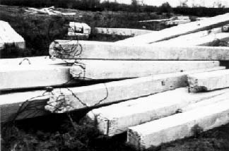
FIGURE 5. Concrete piles damaged by difficult driving conditions.
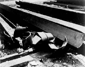
FIGURE 6. Steel H-piles badly damaged by hard driving.
A comprehensive investigation of the design of piles
as structural members was performed to define and establish, through structural
analysis and supporting field data, a rational guideline or design methodology for
determining allowable stress levels for pile design codes used in highway bridge
foundations. These methods must take into account not only the material properties
of the pile itself, but also the individual effects of long-term loads, driving
stresses and driveability, imperfections in form or material, and various environmental
conditions that tend to reduce pile capacity.
As part of the overall review, the investigators studied the
codes and specifications of an array of national and foreign organizations and
code bodies. The basis for each code was reviewed and corroborative data were
assembled to develop improved values of allowable stresses. The claims of
material suppliers for increased allowable stress levels also were evaluated and
documented. Some of the claims were found to be overstated, and all of them
ignored at least one or more of the important factors that govern the structural
strength of a pile.
In general, it was recommended that allowable stress values in use at that time
be decreased for concrete and timber piles and increased for steel piles. The
new procedures for determining appropriate allowable stress levels on a case-by-case
basis according to the major factors governing structural strength of piles
are a significant improvement over the previously unsubstantiated blanket stress
levels. Reasons for each suggested change to then current methods for determining
allowable stress values are documented in the FHWA report (11).
2.6.5 Performance of Pile Driving Systems - Proper construction control of pile driving operations is as essential as good design practices. Construction control is more difficult for piles than for spread footings because the excavation and construction of footings can be observed. The construction control for pile driving involves checking the pile materials and the installation equipment. The pile inspector can visually check many requirements; however, some of the most important checks require instrumentation. The high cost of pile foundations prompted FHWA to seek more efficient pile driving systems as well as more efficient design methods.
Pile driving technology has evolved from an archaic system of
pounding a "stick" in the ground with a heavy mass to a
sophisticated system of installing long, slender structural elements
in a well-defined soil mass. In the previous era it didn't
matter how efficient the pile driving system was because the only
objective was to pound the stick into the ground. However, the
vertical advance of a pile under a given hammer blow can be used as
a measure of the pile's bearing capacity. Thus the hammer
takes on a second function, and doubles as a piece of testing
equipment.
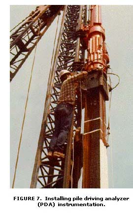 A comprehensive study of available pile driving systems and corresponding measurement
techniques was completed under this research program. In addition to the direct
measurements of output, researchers investigated the usefulness and practicality
of installing gauges (figure 7) and other instrumentation on the pile driving
system to determine performance rating, spot the cause of erratic or inadequate
operation, and evaluate the significance of erratic behavior in terms of performance
capability.
A comprehensive study of available pile driving systems and corresponding measurement
techniques was completed under this research program. In addition to the direct
measurements of output, researchers investigated the usefulness and practicality
of installing gauges (figure 7) and other instrumentation on the pile driving
system to determine performance rating, spot the cause of erratic or inadequate
operation, and evaluate the significance of erratic behavior in terms of performance
capability.
The researchers developed three devices to evaluate the
field performance of pile hammers. The ram velocity measurement (RVM) apparatus uses
radar to record ram velocity as a function of time for conversion to kinetic energy
for driving. The study also developed a system that uses piezoelectric accelerometers
to measure pile hammer impact velocity. This system is referred to as AMS (for Acceleration
Monitoring System). Both the RVM and AMS are expensive and complicated devices
for routine use on pile driving projects. A simpler device, the Saximeter II,
was developed for FHWA to aid the pile inspector in log keeping and monitoring
pile driving performance. It electronically measures blows per minute and
converts time duration to the corresponding fall height (stroke) of the ram, and
converts stroke to the potential energy.
An inspection manual was also developed to aid construction engineers in evaluating
the performance of pile driving systems (12). It can be used to ascertain that
the pile hammer conforms to certain minimum standards, and to record observations
on hammer and driving system behavior. The manual explains the theory of operation
and inspection procedures for various hammer types, describes all components
of the driving systems, includes a glossary of pile driving construction terms,
and provides summary sheets and forms to aid the inspector in recording the
pile installation process. A slide-tape show was also developed to provide a
visual rendering of the inspection manual for instructional purposes.
2.6.6 Pile Wave Equation Technology -
For many years, pile design used pile driving formulae that were established to relate
dynamic driving forces to available pile bearing capacity. The original dynamic
formula was developed more than a hundred years ago and was based on a simple
energy balance between the kinetic energy of the ram at impact and the resulting
work done on the soil. The concept assumed a pure Newtonian impact with no
energy loss.
A close examination of the pile driving process recently disclosed that the
concept of a Newtonian impact does not apply. It was also noted that when the hammer
strikes the pile, a force pulse is created that travels down the pile in a wave shape.
The amplitude of the pile wave decays before reaching the pile tip because of system
damping properties; however, a portion of the force in the wave reaches the tip
and forces the pile to penetrate the soil.
Before the demise of the dynamic driving formulae and before
the wave equation analysis was fully developed, pile designers relied on static
pile analyses to predict pile capacity and determine pile sizes and lengths. The
success of this method depended greatly on the accuracy of boring data and the
engineer's ability to properly classify zones in the subsoil with regard
to relative pile support capability. Static analysis methods will always be very
useful because they are much more accurate than the old driving formulae;
however, the value of wave equation type methods has been steadily
increasing.
The wave equation method is a computer based analysis that was developed
from the classical wave theory, which models wave propagation in a slender
rod subjected to an applied force at one end. Modifications to the classical
theory are necessary to account for changes in the traveling wave form due to
pile and soil properties. If the wave is completely dissipated by the pile material
and soil properties before reaching the pile tip, no penetration will occur. This
can be due to either too small a hammer for the pile, or too small a pile
cross-sectional area specified for the length being driven. Wave equation analysis
can detect both of these scenarios before they happen in the field, plus it can
also predict pile damage if too large a hammer is selected.
Soil data input requires both an understanding of site-specific soil
properties and the effects of pile driving on those properties. These dynamic
properties are known as damping and quake and are roughly correlatable with soil
type. These properties are best determined by experienced geotechnical
engineers. Research was needed to provide better methods to determine soil
damping and quake values from laboratory and/or in situ soil testing equipment
to better predict pile capacity.
2.6.6.1 Pile Capacity Prediction
- In response to this need, FHWA initiated a contract
research study to perform an in-depth assessment of current techniques and
potential methods for determining soil quake and damping input parameters to
the wave equation computer analysis program. The contractor was required to
develop a data base of pile foundation sites containing research-quality soils
data, pile driving records, load test information, and Pile Driving Analyzer
(PDA) data. These data were to be used to make correlations among quake and
damping factors, Wave Equation Analysis Program (WEAP) capacity predictions,
and soil test data. It was also a requirement to locate 6 to 10 actual projects
where load testing and dynamic measurements were made, plus good soil data had
to be available to perform the required correlations to evaluate the newly
developed procedures and propose additional modifications, if necessary.
The following is a reprinting of the report's abstract:
"Research has been conducted on the potential improvement of dynamic
wave equation analysis methodology using in-situ soil testing techniques. As
a basis for this investigation, the literature was reviewed and a summary was
compiled of efforts made to date on the development of models and associated
parameters for pile driving analysis. Furthermore a data base was developed
containing more than 150 cases of test piles with research quality data on static
load tests, dynamic restrike tests, soil information, driving system data and
installation records. One hundred data base cases were subjected to correlation
studies using the CAse Pile Wave Analysis Program (CAPWAP) and various static
analysis methods. This work yielded dynamic soil model parameters which did
not indicate a specific relationship with soil grain size" (13).
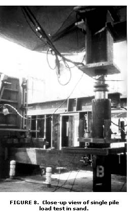 2.6.6.2 Simplified Capacity Predictions -
Static load testing (figure 8) to failure is probably the best method available
to determine the actual static capacity of a pile; however, these tests are
expensive and time consuming. As a result, they are not routinely conducted.
In many cases a load test to twice the design load is conducted to verify safety
factors and save money on the cost to extend the loads to the failure range.
These tests give some measure of assurance to the project design team, but do
little to advance the knowledge of how to design a particular pile in a particular
soil. The simple act of striking a pile with a heavy hammer can also be thought
of as an instantaneous load test to failure; because in order for the pile to
penetrate further into the soil, the soil must fail under the driving forces.
In other words, pile driving is actually a very fast load test under each hammer
blow. With the right type of instrumentation, the engineer can take advantage
of these failure measurements and use the information to make a prediction of
potential static capacity in the field during pile driving operations.
2.6.6.2 Simplified Capacity Predictions -
Static load testing (figure 8) to failure is probably the best method available
to determine the actual static capacity of a pile; however, these tests are
expensive and time consuming. As a result, they are not routinely conducted.
In many cases a load test to twice the design load is conducted to verify safety
factors and save money on the cost to extend the loads to the failure range.
These tests give some measure of assurance to the project design team, but do
little to advance the knowledge of how to design a particular pile in a particular
soil. The simple act of striking a pile with a heavy hammer can also be thought
of as an instantaneous load test to failure; because in order for the pile to
penetrate further into the soil, the soil must fail under the driving forces.
In other words, pile driving is actually a very fast load test under each hammer
blow. With the right type of instrumentation, the engineer can take advantage
of these failure measurements and use the information to make a prediction of
potential static capacity in the field during pile driving operations.
This concept was proposed to FHWA by the developer for further study. The
idea to develop a simplified method based on energy balance between
the total energy delivered to the pile and the work done by the
pile/soil system was examined under a research contract study in the
early 1990's. This method, called the "Energy
Approach", uses the calculated transferred energy and maximum
pile displacement values from the measured data, together with the
field blow counts as input parameters to calculate the pile
capacity.
To verify and refine the new method, two large data
sets were retrieved from the FHWA Deep Foundations Load Test Data Base
(see section 5.2). One set contains 208 dynamic measurement cases on 120 piles
monitored during driving and followed by a static load test to failure. These
cases reflect various combinations of soil-pile driving scenarios. The other
set contains data on 403 piles monitored during driving, but without static
load test data.
The Energy Approach method was found to be very accurate in predicting the pile
capacities that were measured in the static load tests. These estimates were
also found to be more accurate than the sophisticated office methods commonly
used in engineering practice. This comparison was especially true for records
obtained at the end of initial driving. This approach can be used in place of
or as an independent check of the office methods (14).
2.6.7 Micropiles - Micropile
technology was conceived in Italy in the early 1950's to fill the need for
an economical and versatile foundation system that could be used to underpin,
repair or retrofit badly damaged infrastructure elements in war-torn Italian
cities. It was introduced in the United States about 20 years later; however, it
did not catch on near as much as it did in Europe, especially, in the late
1980's and early 1990's. In addition to static applications, significant
growth in the use of this technology has occurred in seismic and slope
Stabilization applications.
All of these uses are directly applicable to highway projects, which caught
the eye and interest of FHWA geotechnical engineers. Two major earthquakes in
California and one in Japan also stirred interest in the use of micropiles for
seismic retrofit of highway bridge foundations. At the same time, the French
Highway Administration began a major research project to investigate the basic
mechanisms and engineering characteristics of micropile systems.
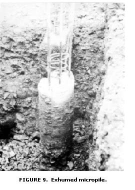 Micropiles are defined as small-diameter, drilled
piles composed of placed or injected grout with some form of steel reinforcement
in the center of the grout to resist the bulk of the design load. The central
reinforcing element is either a high-strength steel bar or tube that is secured
in the grout that is injected under high pressure to improve bonding with the
surrounding soil. Micropiles can be installed through virtually any ground condition
and at any inclination. Modern construction techniques keep noise and vibration
to a minimum, and they can be constructed under limited headroom conditions
to within a few millimeters of adjacent properties. Figure 9 shows an early
model micropile that was exhumed for inspection purposes.
Micropiles are defined as small-diameter, drilled
piles composed of placed or injected grout with some form of steel reinforcement
in the center of the grout to resist the bulk of the design load. The central
reinforcing element is either a high-strength steel bar or tube that is secured
in the grout that is injected under high pressure to improve bonding with the
surrounding soil. Micropiles can be installed through virtually any ground condition
and at any inclination. Modern construction techniques keep noise and vibration
to a minimum, and they can be constructed under limited headroom conditions
to within a few millimeters of adjacent properties. Figure 9 shows an early
model micropile that was exhumed for inspection purposes.
In 1992 FHWA was invited to become a cooperative
research partner in the French micropile project.
The major objective of this cooperative research project was to establish reliable
engineering guidelines and safe design methods for the use of micropiles in
the reinforcement and Stabilization of foundations and slopes.
It was
anticipated that the development of reliable engineering guidelines, combined
with site monitoring for field performance assessment of micropile systems,
would significantly increase the engineer's confidence in the technique
and, thereby, greatly enhance its expansion to new fields of application.
The initial investigations included a comprehensive review and critical assessment
of available information on current state of the practice, research case studies,
site performance monitoring, quality control issues, and any comparisons or
analyses of current codes of practice. Several ongoing micropile construction
projects were also instrumented and monitored to provide researchers with additional
case histories to study and evaluate. The major physical experimental tasks
involved centrifuge modeling and related analytical/numerical simulations, full-scale
testing, and field monitoring, which were designed to study the engineering
behavior of individual micropiles and micropile groups and/or systems under
axial and transverse load response modes (figure 10). Buckling, corrosion, and
seismic aspects were also investigated under actual working conditions as well
as at failure under ultimate loading.
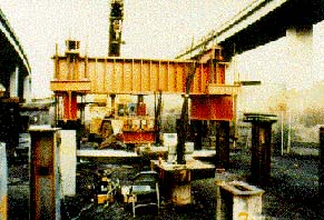
FIGURE 10. Load testing of micropiles in California.
2.6.7.1 State-of-the-Practice Review - In 1993 FHWA initiated a contract to produce a comprehensive review document that would delineate all of the known information about micropile technology that could be gathered from various organizations around the world. The contractor put together an international group of experts to evaluate the information obtained in the surveys. The review report (15) provides a comprehensive introduction to micropile technology, and assisted FHWA in developing an engineering guidelines manual (7) containing reliable design guides, construction specifications, and quality-control procedures for the wide spectrum of micropile applications.
2.6.7.2 Seismic Behavior of Micropiles - In 1995, FHWA initiated a contract research study to develop improved seismic design methods for micropile systems used in new construction in earthquake zones, seismic retrofitting of bridge foundations, vertical excavation retainment systems, and slope Stabilization. Laboratory centrifugal model tests were conducted to correlate with numerical model studies on various micropile systems (isolated piles, groups, and networks of piles) to evaluate their behavior under axial, lateral, and combined loadings in selected engineering applications. Shaking table tests were also conducted at Christchurch University in New Zealand as part of the overall study to improve seismic design methods. This study is scheduled to be completed after this report is printed.
2.6.8 Publications and Implementation Items - Research and development activities for pile foundations were very successful. Results were documented in numerous reports, and several technology sharing reports were issued to help implement the findings. Several workshops and symposia were held to promote the new guidelines and prediction methodologies that were developed under the research program. Several new articles were added to the AASHTO Bridge Specifications and many others were updated based on the FHWA pile foundation research results (see chapter 7).
2.7 Pile Groups
The state of the art for pile foundation design at
the beginning of this project did not include an accurate method for relating
the ultimate bearing capacity and settlement behavior of a single pile to the
behavior of a group of closely spaced piles. To develop such a method, it was
necessary to conduct field load tests to failure of full-scale pile groups to
obtain field data that were useful in interpreting fundamental phenomena that
control the behavior of groups of driven piles.
Older methods of pile group design treated the group as a collection of
individual piles requiring an adjustment factor. Predicting the behavior of
pile groups required correction of the load capacity of the individual piles
in the group for the interaction effects transmitted through the soil mass.
How this should be done was never certain, and it was recognized that it
would probably be different in cohesive as contrasted to granular soils.
In 1980, FHWA initiated a research program to investigate
pile group behavior through carefully performed experiments. First, existing
mathematical models used to design pile groups were identified and evaluated.
From this evaluation, the "hybrid model" was selected and used to
analyze a proposed full-scale pile group to be load tested.
The hybrid model, a load-deformation model, reasonably predicts load versus
settlement, load transfer patterns, and load distribution to pile heads. The
model was especially helpful in designing the instrumentation system for the
full-scale pile group load test. The field data acquired from the load tests
were used to refine the hybrid method, which led to the FHWA PILGP1 computer
program, a modification and refinement of the hybrid
model (see section 2.7.3).
2.7.1 Pile Groups in Clay - To develop
the field data required to verify and refine PILGP1, 11 instrumented steel pipe
piles were driven into a very stiff, saturated, over-consolidated clay soil at
the University of Houston, Texas, campus. The outside diameter of the piles was
273 mm (10.75 in), with a wall thickness of 9.27 mm (0.365 in). The piles were
driven closed-ended 13.1 m (43 ft) deep. Nine piles were driven in a 3 x 3
square array on a spacing of three pile diameters. The two remaining piles were
driven apart from the group to serve as control piles.
Each of the 11 piles was instrumented with full
bridge strain gauge transducers and mechanical telltales to monitor load
transfer from the piles to the surrounding soil. Four of the group piles and one
control pile were instrumented with piezometers and lateral total pressure
cells. The surrounding soil also was instrumented with piezometers and vertical
ground movement devices. Electronic load cells measured applied loads, and
settlements were measured at each pile head. Three-dimensional translations were
measured on the massive concrete pile cap that was suspended off the ground.
The load testing program consisted of 11 compression and 6 uplift (tension)
tests, all of which were carried to ultimate failure loads. The control piles
were load tested in compression at three time intervals to study the effect
of soil setup. Each control pile also was tested in uplift. The nine-pile group
(figure 11) was tested in compression atthree time intervals to assess setup
characteristics of the group. Four of the group piles were tested in uplift;
however, these tests were preceded by compression tests on two smaller groups
of four and five piles. The five-pile subgroup was formed by cutting away the
four corner piles, leaving the four edge piles and the center pile. The four-pile
subgroup was formed by removing the center pile (8,9).
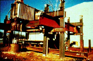
FIGURE 11. Pile group load test in clay.
2.7.2 Pile Groups in Sand -
A second pile group load test study was performed on a group of eight timber piles in
sands at the Locks and Dam No. 26 near Alton, Illinois, as part of an evaluation
of several rehabilitation schemes for the distressed locks and dam structures.
The timber piles were instrumented to measure load transfer and deformation up
to and including the failure load. The acquired field data were used to evaluate
and refine the PILGP1 program (16).
The third pile group study involved load testing five single piles and a
group of five piles in sand at a test site in Hunters Point, California (figure
12). The load test results were also used to evaluate PILGP1 and a simplified
procedure developed under previous studies of the behavior of single piles and
pile groups. Data were obtained on the comparative behavior of piles of
different types with the same relative geometry. Residual stresses, load
transfer, and load-settlement characteristics were measured and used to evaluate
the effectiveness of the new pile design and analysis procedures. An isolated
control pile and three of the five group piles were fully instrumented, to
obtain the load-response data for the analysis. Soil and ground water conditions
were evaluated with standard and state-of-the-art equipment, such as Standard
Penetration Test, Dutch Cone, Stepped Bladed Vane, Dilatometer, and
Pressuremeter testing devices (17). Figure 13 shows a closeup view of the
test pile group and two soil instrumentation boreholes.
After each of the first and third pile group load test studies, a pile group
prediction symposium was held to discuss the test results and evaluate the most
popular pile group design methods in use at that time (18,19,20).
|
|
|
|
FIGURE 12. Reaction frame
for pile group |
FIGURE 13. Instrumentation
bore holes |
2.7.3 Predictive Model for Pile Group Design and
Analysis (PILGP1) - A comprehensive computer-aided design
method called PILGP1 was developed for FHWA at the University of Houston for
the design and analysis of pile groups. It is a load deformation model that
predicts load versus settlement behavior, load transfer patterns, and load
distribution to pile heads. The model designs the pile group as an interactive
element rather than as a collection of individual piles requiring an adjustment
factor. It was developed from the results of the first full-scale field load
test program on single piles and pile groups. Two additional full-scale field
load test programs were later completed to further refine and validate the
computer model. The current version of the model (PILGP2) is being tested
by several consulting firms, States, and Federal agencies. Continued
testing, evaluation, and refinement of the model is currently under way.
The development and verification of PILGP1 was based primarily on the full-scale
field tests of pile group behavior under both working loads and failure conditions.
Because of the many variables involved, numerous full-scale field tests needed
to be conducted to provide a statistically meaningful data base. However, the
costs involved in full-scale field testing significantly restricted the number
of tests that could be conducted. The alternatives to full-scale field testing
are model field testing, laboratory model studies, and centrifuge model testing.
2.7.4 In-Service Monitoring of Pile Groups - The three full-scale pile group load tests to failure produced very accurate and valuable data; however, they were very expensive to conduct. In addition to the pile group load tests to failure, four full-scale field projects were initiated with FHWA research funding to observe pile group behavior under working loads. The short- and long-term behavior of the in-service piles was compared with analytical predictions made by PILGP1.
One of the projects was located on the Natchez Trace Parkway
(NTP) in Mississippi, where a pile-supported bridge abutment was instrumented to obtain
load transfer data on a group of six steel piles (12 HP 53) in soft clay and silt.
Samples of load/settlement curve data are shown in figure 14. Another project was located at
Fort Belvoir, Virginia, where soil and pile conditions were similar to those at the
Mississippi project. Instrument readings were taken weekly during the first year at
each site, monthly during the second year, and quarterly for several years.
The third site, at the Mocks Bottom over-crossing in Portland, Oregon, near Swan Island,
is underlain by a thick compressible clayey silt deposit. High down-drag loads
were expected because of the approach embankment loads on the compressible soil.
A bitumen coating was used to reduce down-drag loads by about 90 percent.
Although the bitumen-coated piles cost about 15 percent more than the uncoated
piles, fewer piles were required. Pile instrumentation included settlement and
load transfer monitoring.
The fourth site was located at the West Seattle Freeway in Washington where
a group of twelve 310-mm- (12-in-) diameter concrete piles supports a pier in
medium-dense sands. The bridge pier and pile cap were instrumented to measure
the amount of load transferred to the pile cap, and each pile was instrumented
to measure load transfer from the pile cap to the top of the piles. Three piles
were instrumented for load transfer along the entire pile length of 30.5 m
(100 ft).
2.7.5 Model Testing - The high cost, measured in both time and
money, of obtaining high quality data from full-scale load tests on single piles
and pile groups, led to the FHWA staff study to determine if accurate data could
be obtained by conducting model tests in simulated ground conditions.
Using carefully controlled large test pits located at FHWA's
Turner-Fairbank Highway Research Center (TFHRC), more than 200 model tests on
single piles and pile groups have been completed on several different types of
piles in sand and clay soils. These data are being compared with the carefully
controlled centrifugal and full-scale single pile and pile group load test data.
This work is continuing as more variables are studied, and results are entered
in the load test data base to be used for verifying and refining the PILGP1
model.
An investigation of scale effects is an important part of this study to
determine if the model test data can be productively correlated with the load
test data of the full-scale field tests. The establishment of appropriate scale
factors allowed more model tests to be substituted for expensive full-scale tests.
Small-scale models permit numerous parametric studies at a reasonable cost, and
allow soils and other conditions to be carefully controlled.
The first series of laboratory model tests was patterned after the timber pile
field study at Alton, Illinois. The sandy soil at the Alton test site was matched
as closely as possible at TFHRC. Model load tests were run on single piles and
pile groups (figure 15) at 1/20, 1/15, 1/10, and 1/3 full scale. As a minimum,
three load tests were performed for each scale. Each pile was instrumented with
strain gauges to measure load transfer.
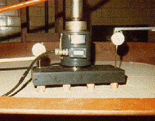
FIGURE 15. Load test on small-scale model pile group in test tank.
The second series of laboratory model tests was patterned after the full-scale load test on steel pipe piles in clay. Model tests were run at 1/15, 1/10, 1/6, and 1/4 full scale. The laboratory model tests on the 1/20, 1/15, and 1/10 scales were performed in a steel tank 1.5 m (5 ft) in diameter and 1.5 m (5 ft) deep. Because the 1/6, 1/4, and 1/3 scale models were too large to be tested in the laboratory test mold, outdoor test pits were constructed at the TFHRC site (figure 16). The third series of tests was patterned after the full-scale pile group load test to failure at Hunters Point, California.
FIGURE 16. Load test on large-scale model pile group in test pit.
The scaling factors identified in this study were used to establish relationships between load deformation behavior of reduced-scale and full-scale piles and pile groups. These small-scale tests provided a significant amount of data to validate PILGP1 at less cost than full-scale field testing.
2.7.6 Centrifuge Model Testing - Small-scale
models permit parametric studies at reasonable cost and allow soils and other
conditions to be carefully controlled; however, it is difficult to achieve
similitude between corresponding stresses and strains in the model and
prototype. The response to load of a small pile and a large pile cannot be
modeled by any simple, direct relationship derived by ordinary dimensional
analysis. The question of scale effects must be resolved before any useful
relationships for pile design can be developed.
Models of large, heavy structures where gravity is a
principal loading factor are not effective indicators of prototype behavior
because the state of stress in the model caused by self-weight will be much
lower than in the prototype. If the model can be placed in an artificially high
gravitational field, the state of stress limitation can be counteracted almost
entirely. A centrifuge apparatus provides the necessary accelerated gravity rate
to load test the model under simulated gravitational forces. However, to
accurately measure stresses and strains, the centrifuge must be able to
accommodate a model that is large enough to handle the required instrumentation.
The larger centrifuge capacity provides more accuracy in direct modeling of
large prototype structures. A pilot study validated the feasibility of using
centrifuge techniques for corroborating the PILGP1 mathematical model.
In a larger study, the centrifuge
was used to test models of the full-scale pile groups that were load tested to
failure in the previously described field studies. The combination of centrifuge
model testing and small-scale laboratory testing of conventional models at TFHRC
provided valuable physical data to establish relationships between pile groups
of varying scales in the same environment.
The larger, more comprehensive centrifuge testing program on single piles and
pile groups was performed in sand and clay soils. The results were used to test
and verify assumed similitude relationships between scaled models and full-scale
prototypes. The load deflection and load transfer data were used to predict
full-scale performance and compared favorably with both measured results and
predictions made by computer generated results. The experimental procedures
developed and the verification established in the program has encouraged the
investigation of the many factors that influence pile performance under controlled
laboratory settings. The centrifuge technique should also be useful and very
cost-effective in establishing the predicted behavior and the sensitivity to
design changes of pile foundations for large projects (21).
2.7.7 Lateral Loads on Pile Groups - Several
analysis and design methods for pile groups under lateral loading have been
proposed, but none had been validated using carefully performed field
experiments on full-scale structures. The theory of elasticity and a number of
"efficiency" formulas often were used as analytical methods for
lateral load design. One of the most promising methods is called the
Poulos-Focht-Koch (PFK) procedure. This method was evaluated through field load
tests. Data from the load tests also were used to develop an improved method of
analysis.
The main objectives of the field load tests were to provide high-quality
field data on the performance of a full-scale pile group under lateral loading
and to compare measured response with that predicted by the PFK method. The load
test was performed at the FHWA pile group test site at the University of Houston,
Texas, campus using the same piles and some of the instrumentation used in the
vertical load tests previously described.
The results of these tests were also evaluated under a cooperative study with
the U.S. Army Corps of Engineers that was performed at the University of Houston
site. After the lateral load tests in clay were completed, the researchers replaced
the top 3 m (10 ft) of clay with sand backfill and repeated the load tests.
The test results were used to refine and validate the predictive models (22).
2.7.8 Publications and Implementation Items - Research and development activities for pile group foundations were very successful. Numerous quality reports were generated from an unprecedented program of research into an area where few have ventured and none to the same extent. Textbooks and specification codes have incorporated the results of these tests, and the state of the art was advanced significantly.
2.8 Drilled Shafts
A drilled shaft is a machine-excavated circular hole in soil and/or rock that
is filled with concrete and reinforcing steel to support heavy structural loads
in single or multiple units. Vertical loads are resisted by both the base area
of the shaft and in side friction which can be very significant because the
concrete is cast wet and cures directly against the soil forming the walls of
the borehole. They are sometimes socketed in rock, and steel casing is sometimes
required for hole Stabilization that may or may not be removed. Horizontal load
is resisted by the shaft in horizontal bearing against the surrounding soil
or rock.
Drilled shafts have many advantages that set them apart from piles and spread
footings. In fact each foundation element has certain pros and cons that have
to be weighed one against the other when deciding on which system to use in
a particular design situation. Each system also has several disadvantages that
have to be evaluated for each design situation. To give confidence as to performance
with respect to the intended task, any foundation element requires both a reliable
method of construction and a standard to define acceptance after construction.
In this regard, drilled shafts were considered to be less reliable than others
because of the uncertainty of the effects of construction on the actual service
behavior, and the limited knowledge of either reliable quality-control tests
to locate and evaluate defects or inexpensive load test procedures. Even if
there are only occasional failures, they highlight the variables and unknowns
present when working underground, particularly in water-bearing and potentially
caving soils. This results in a lower risk tolerance for a single or double
shaft supported pier compared with multiple pile supported foundations.
Because drilled shafts for many design situations offer higher capacities with
potentially better economics than driven piles, the FHWA has spent considerable
time and money in research and development of improved design and construction
guidelines for drilled shafts. Other advantages include less noise and vibration
during construction and the ability to go very deep to avoid scour problems.
A major research program was designed to evaluate existing nondestructive testing
techniques for identifying defects and/or results of adverse downhole conditions
that impact the load transfer/settlement behavior of drilled shafts. It was
also planned to develop rational acceptance criteria for defective drilled shafts
on the basis of quality control during construction, plus a field test program
to verify the research findings that included a search for more economical methods
to test shaft capacity with and without defects.
2.8.1 Nondestructive Evaluation (NDE) of Drilled Shafts - In July 1988, FHWA initiated a contract research study to examine drilled shafts for the effect of defects on performance, and to develop acceptance criteria for use by construction engineers to accept, reject, or modify a newly constructed drilled shaft. The study included the construction of 20 drilled shafts with and without defects for different soil sites located in California and Texas (figure 17). The shafts were constructed using different techniques: dry construction, and wet construction using drilling water, controlled bentonite slurry, and controlled polymer slurry. Five instrumented shafts were statically load tested (figure 18) to determine the effect of the man-made defects on shaft performance, and all shafts were dynamically load tested to correlate with static results. All shafts were tested non-destructively using both surface reflection and direct transmission techniques to determine their effectiveness in identifying defects and/or the results of adverse down-hole conditions that impact the load/settlement behavior of the shafts; results were summarized and evaluated in the report. The allowable defect criteria developed consider the design basis, the ratio of design stress to a maximum code allowable, the type of stress, the level of quality control, and the risk tolerance.
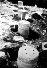
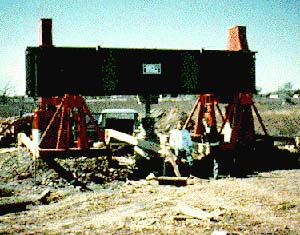
FIGURE 18. Vertical load test of defective drilled shaft.
In addition to the establishment of acceptance criteria, a rating guideline for implementing special integrity testing and a decision tree were developed to guide the engineer or decision maker through construction of a drilled shaft project that includes nondestructive testing. The report also includes detailed information on four promising low-strain NDE techniques (sonic echo, impulse response, cross-hole sonic logging, and gamma-gamma logging), which can be used as part of the quality control procedure, plus information on three alternative load test procedures that show high potential for being economical substitutes for expensive static load tests (see section 2.10).
The sonic echo (SE) and impulse response (IR)
test methods use impact energy applied to the top of the shaft to
generate energy waves down the shaft and return to a receiver that
measures the vibration response. These methods are not able to
locate deep defects and they aren't able to detect the size and
location of the defects. Smaller defects lying below a larger defect
are easily masked from above. Cross-hole sonic logging (CSL) and
gamma-gamma logging (GGL) overcome these problems by being downhole
methods that pass ultrasonic or radiation waves through the concrete
between source and receiver probes in a water-filled tube or hole
pair as the probe cables are pulled from the bottom back to the
surface over a depth measurement wheel. These methods test the
quality of the concrete lying between a pair of tubes. Four tubes
installed in a shaft before concreting gives sufficient coverage to
adequately inspect a shaft for defects. Figure 19 shows an end view
of a rebar cage with four NDE access tubes.
Results clearly show that the CSL method is superior. The GGL method requires
a radiation source and requires PVC tubes because steel is not compatible with
the radioactive materials. This method is also sensitive to defects close to
the test tubes, and doesn't have the same range away from the installed tubes
that CSL has. In addition, CSL is generally much faster to perform and does
not use radioactive materials (23). Figure 20 shows a technician performing
a surface deflection test on one of the defective shafts.
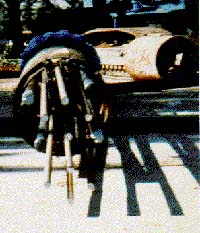
FIGURE 19. Instrumented drilled shaft showing man-made defect and NDE access tubes.
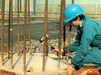
FIGURE 20. Low-strain impact test with instrumented hammer and geophone sensor.
2.8.2 Drilled Shafts in Intermediate Geomaterials - Current design methods for drilled shafts in soil or competent rock are reasonably well-founded; however, comparatively little effort has been expended to determine design parameters for intermediate materials such as shales, claystones, and marls. In September 1991, FHWA signed a second contract to develop, test, and recommend criteria for determining appropriate exploration, in-situ testing, and the necessary inputs to the load transfer function or other design methods for drilled shafts in intermediate geomaterials.
The contract consisted of essentially three tasks:
Data were collected from projects in Australia, Georgia, Texas, Massachusetts,
and Kentucky. These data have been used to develop the criteria for exploration
and sampling of soil materials to use for developing new load transfer functions
for the design of drilled shafts in shales, tills, and other materials between
soils and hard rock. A field test program was also designed to validate the
new design methods (24).
2.8.3 Free Fall of Concrete in Drilled Shafts
- This study developed information and data that were
used to justify increased depths of free-fall placement of concrete into
properly constructed clean and dry shafts without meaningful loss of strength
or segregation of the concrete aggregate. The report of findings has had a
significant economic impact on the drilled shaft industry.
Prior to this study, the question of whether the free-fall of concrete
over long distances adversely affects the concrete strength and integrity
in drilled shafts persisted in the minds of many engineers and construction
inspectors. This question persisted despite past efforts to answer it and
dispel the concern that concrete does not segregate during free-fall at any
height, and that free-fall placement can be accomplished without adverse
effect on the concrete.
To accomplish the research goals in a cost-effective way, four 18-m-
(60-ft-) long, 0.9-m- (3-ft-) diameter shafts evenly spaced and tangent to a
central 1.5-m- (5-ft-) diameter access shaft were constructed. The four test
shafts were divided into six 3-m (10-ft) sections with one of four different
concrete mixes placed in each section. The slump, maximum aggregate size,
and placement procedures were also varied. The low slump mixes were also
placed with and without super plasticizer. The three placement procedures
were free-fall central drop with careful control to be sure that the
concrete didn't strike the rebar cage, free-fall sloppy drop with effort
actually made to see that the free-falling concrete did hit the rebar cage, and
tremie placement with a tremie pipe extended all the way to the concrete
placement level.
The results of the research were very conclusive and positive.
Construction codes have been changed in many cities, counties, and
States, accordingly. More specifically, the results were as follows:
None of the lifts placed by central drop free-fall procedures within the research
program exhibited any signs of aggregate segregation. The design strengths of
all centrally dropped lifts varied from 13 percent less to 20 percent more than
the reference cylinder strengths. All of the strengths were well above the
intended design strength.
Due to the small variation in the compressive core strength and lack of aggregate
segregation, no definitive effect of slump, aggregate size, height of drop,
depth of fluid pressure, or addition of super plasticizer was discerned.
Surprisingly, in six out of seven direct comparisons made between sloppy drop
and central drop placement procedures, the sloppy drop methods actually resulted
in higher average compressive core strengths than equivalent central drop procedures.
Also, no segregation of aggregate was noted for any of the sloppy drop mixes placed.
Thus, on the basis of this research, it is concluded that striking the rebar
cage or the side of the shaft does not have a detrimental effect on the strength
or integrity of the concrete.
Due to the high strengths and lack of segregation that were apparent in all
of the sloppy drop lifts, the effects of aggregate size, slump, height of drop,
height of fluid pressure, and addition of super plasticizer did not appear to
affect the results in a meaningful way for the well-designed concrete mixes.
Even though sloppy drop procedures were not found to affect the strength or
segregation of the concrete, it is not intended that contractors should begin
to place concrete in a haphazard fashion. The sloppy drop procedure adversely
affected the placement of the rebar cage and also caused additional concrete
contamination as a result of traveling down the soil sides of the shaft. In
all cases, the shafts were fully formed and no honeycombing, voiding or exposed
rebar was evident (25).
2.8.4 Load and Resistance Factor Design of Drilled
Shafts - In early 1997, FHWA co-funded a research study on
"Resistance Factors for Drilled Shafts with Minor Defects" with the
Association of Drilled Shafts Contractors (ADSC) and a number of SHA's including
California, Florida, Illinois, Minnesota, Montana, North Carolina, Pennsylvania,
and South Dakota. The objective was to develop design techniques to account for
sub-detectable minor defects that can occur during construction. The analytical
study and most of the experimental work was done by the University of Houston at
its National Geotechnical Experimentation Sites (NGES) facility. Some of the
future testing will be done by FHWA staff at the TFHRC.
It is proposed to derive resistance factors (or "workmanship
factors") for drilled shafts through analytical modeling that will be
calibrated by performing field loading tests to structural failure on drilled
shafts with selected defects. The load testing will primarily be lateral because
the loss of moment resistance in the lateral mode of loading is potentially more
severe than loss of axial capacity for drilled shafts with steel percentages
normally used in highway bridge construction.
A computer program called LPILE Plus was modified to perform
accurate and realistic modeling of the influence of minor defects on drilled
shaft behavior. The modified version allows for the development of an
independent stress-strain curve within the defect area. It also allows for a
reduction in the tensile strength of both the defective and nondefective
portions of the shaft section. A defect may be located in either the compressive
or tensile portion of the shaft. It is also possible to include more than one
defect in the same section. Six field lateral loading tests were conducted to
verify and calibrate the modified LPILE model.
Lateral load tests were conducted by jacking a test shaft
against a reaction frame consisting of a wide flange steel girder supported by
two reaction shafts. A manual jacking system was used to jack the test shaft
against the reaction frame. Loads were measured with a load cell and dial gauges
were used to monitor lateral deflections of the test shafts. All test shafts
were constructed under wet conditions using a polymer slurry.
The test shafts were then extracted and examined
carefully to determine the location of the plastic hinges, and to caliper the
exact dimensions along the shaft axes. The results of the load tests will be
used to verify or to calibrate the modified version of LPILE. This modeling will
be eventually used to develop recommendations for resistance factors for drilled
shafts under combined axial and lateral loading. Preliminary recommendations
will be developed in this phase of the research, while more general and refined
recommendations will be developed in the following phases if the results of the
preliminary phase justify further study.
Because typical drilled shaft defects are usually found at the boundaries
between soil and concrete, they can have effects on both the structural
performance of the drilled shafts and the soil-structure interaction. To isolate
the effect of the structural defects from the variation in the soil resistance,
structural laboratory tests will be conducted on slightly defective shafts out
of the soil at the TFHRC, if the preliminary field test results appear to
justify the effort. The results of this testing program will also be used to
verify the method in the modified version of LPILE that is used to model the
changes in cross-section and stress-strain behavior within the concrete drilled
shaft.
Eight drilled shafts will be tested in the TFHRC laboratory experiment.
Both the diameter and steel reinforcement of the laboratory experiment will be
identical to those of the field load tests. The laboratory test shafts will
include defects essentially similar to those included in the field tests. To
investigate the effect of rebar corrosion, the diameter of the rebars of two
additional defective shafts will be reduced to one-third of the original size
within the defect. Six slightly defective drilled shafts will be tested under
pure bending moment conditions. One of the other two shafts will be tested under
combined shear and bending moment, and the last shaft will have no defects
(reference shaft) and will be tested under pure bending moment conditions.
If the results of the load tests at TFHRC and NGES-UH prove
successful, additional field loading tests will be conducted on slightly
defective shafts over a larger range of soil conditions and for a larger range
of defect types sufficient to provide recommendations for the AASHTO code
committees. It is also possible that the testing will be extended to include
fixed-headed shafts because the preliminary work only looked at free-headed
shafts.
It is expected that these results will help to solve the problem or source of
conflict between some (usually owners) who interpret any anomaly that shows
up on NDE signatures as a defect and others (usually contractors) who believe
that all anomalies are not necessarily defects that require attention. Serious
defects require further probing, immediate repair, or penalty charges assessed
against the contractor; however, minor defects should be accounted for in design
through the derivation of appropriate resistance factors.
2.8.5 Publications and Implementation Items - Research and development activities for drilled shafts were very successful. Several quality reports were generated and appropriate specifications and codes were revised (see chapter 7) to reflect the positive results and improved procedures developed under the research program. The FHWA design manual and instructional workshops were also updated to reflect the advancements and contributions of this program.
2.9 Spread Footings
Foundation
engineering is one of the oldest professions of mankind. The major decision in
selecting a foundation system has always been whether to use shallow or deep
foundations to support a superstructure. Foundation support is achieved by
transferring the loads to the ground materials without incurring excessive
settlements or distortions. Shallow foundations (spread footings or mats)
normally are less expensive to construct than deep foundations (piles, drilled
shafts, or caissons). However, surface soils usually are less capable of
supporting heavy loads than deep soil deposits or bedrock. Deep foundations
provide extra security against bearing capacity failure or settlement. A greater
risk of unexpected engineering and contractual problems exists, however, during
deep foundation installation. Engineering and cost analyses are necessary to
determine the proper foundation system for major structures, such as bridges,
buildings, dams, and nuclear power plants.
The use of spread footings to support highway bridges in the
United States varies widely between States and appears to be far below the
optimum level. A recent survey by FHWA determined that most States use pile
foundations to support the majority of their bridges. The extensive use of piles
to support U.S. highway bridges is contrasted by the extensive use of spread
footings to support highway bridges in some foreign countries. For example,
highway bridges in England seldom are founded on piles despite severe subsidence
problems from coal mining. Another contrast can be seen in the building industry
where spread footings and mat foundations are used quite extensively even though
building elements (for example, doors, windows, elevator shafts, and utilities)
have less tolerance to settlement than bridges.
In the United States, many tons (megagrams) of pile
materials and large sums of money have been devoted to using pile foundations
where spread footings might have been appropriate. The extensive use of piles in
highway bridge foundations may have been encouraged by the AASHTO Bridge
Specifications, which at one time stated that "piling shall be considered
when footings cannot, at reasonable expense, be founded on rock or other solid
foundation material" (circa 1990).
Some of the reasons that piles were preferred over spread footings as a foundation
for highway bridges include the following:
The advent of reinforced concrete in the early
1900's and recent improvements in excavation technology have increased greatly
the appeal of spread footings for bridge foundations. Modern soil mechanics
and improved methods of site investigation and laboratory testing have improved the
accuracy of settlement and bearing capacity predictions. Also, compaction
control and improved grading procedures have minimized spread footings being
founded on weak and/or compressible soils. Finally, special ground
improvement techniques such as soil reinforcement, stone columns and dynamic
compaction have increased the attractiveness and applicability of spread
footings.
Many highway agencies have a policy not to use spread footings on cohesive
soils because of the concern for bearing capacity failure and/or excessive settlement.
This is a conservative approach because some cohesive soil deposits
(especially over-consolidated clays) can support heavy bridge loads without
distress resulting. Although bearing capacity on sands is not a problem,
some highway agencies do not use spread footings on cohesionless soils
because of the concern for excessive settlement. This also is a conservative
policy because a spread footing on sand usually will provide satis-factory
support because consolidation of sands usually is minimal and occurs
rapidly. Most of the settlement occurs before the sensitive superstructure
elements are erected.
The use of spread footings on compacted fill also is infrequent. Although
a properly compacted fill often is stronger and more stable than natural ground and
easily able to support a spread footing, designers often use spread footings
on in-situ soils and avoid their use on prepared fills. Large settlements
from fills usually can be traced to older, nonuniform fills that may have
been constructed of poor soils or uncompacted waste materials dumped on
unprepared natural ground surfaces. However, the use of random, uncontrolled
fill in modern highway construction, especially near bridges, is readily
avoidable. The Connecticut and Washington State transportation departments
frequently support bridge abutments on spread footings on compacted fill.
A foundation system must be functional as well as safe. There is a wide degree
of engineering performance between an unyielding support system and one that
fails. Persistent maintenance problems and failures of noncritical elements
(such as parapet walls and joints) are expensive to correct and should be avoided
if peculiar to certain systems, situations, or methodologies. To improve the
design process, engineers should correlate functional distress (bumps, cracks,
and misalignments) with system characteristics (abutment type, soil type, superstructure
type, and amount and kind of movement) to determine where spread footings are
and are not appropriate.
2.9.1 Performance Evaluation Studies -
To increase the number of documented case studies of spread footing
performance, FHWA staff, in cooperation with the Washington State Department
of Transportation (WASHDOT), evaluated the performance of numerous highway
bridge abutments supported by spread footings on compacted fill. During
this review, the structural condition of 148 highway bridges throughout
Washington State was visually inspected. The approach pavements and other
bridge appurtenances also were inspected for damage or distress that could
be attributed to the use of spread footings on compacted fill.
On the basis of this review and detailed investigations of the foundation
movement of 28 selected bridges, it was concluded that spread footings can provide a satisfactory alternative
to piles, especially when high embankments of good-quality borrow materials
are constructed over satisfactory foundation soils. None of the bridges
investigated in Washington displayed any safety problems or serious
functional distress; all bridges were in good condition (26).
On the basis of the results of the Washington Department of Transportation
study, FHWA decided to expand the idea of spread footing evaluations by initiating
a comprehensive field investigation of 10 new bridges being constructed in 5
northeastern states. Under this research contract, a long-term study of the settlement
performance of 24 spread footings supported on sand was completed to provide
a reliable data base for engineering evaluation. Figure 21 illustrates the
instrumentation monitoring plan for this study.
The results of the northeastern bridge studies served to confirm the performance
results of the WASHDOT study and added to the value of the FHWA data base. The
researchers were also able to locate 10 good-quality case histories in the literature
for use in the data base. Many cases were identified but most were found to
be lacking sufficient settlement or soils data to be included in the study.
It was also noted that all of the case histories in the data base represented
actual projects where loads were limited to working stress levels. A definite
need existed to obtain settlement and soils data at failure loads to provide
a larger and more comprehensive statistical basis to judge the effectiveness
of settlement predictions and the satisfactory performance of spread footings
on sand (27).
![]()
FIGURE 21. Schematic of instrumentation plan for spread footing performance evaluation study.
A follow-on study was initiated to develop a rational prediction method and a user-friendly data base with prediction and correlations modules for use in designing spread footings on sand. As part of this study, the contractor built five large model footings on sand at the Texas A&M University's National Geotechnical Experimentation Site. Each footing was carefully instrumented and load tested (figure 22) to failure (28). A prediction symposium was also held to discuss the results of the load test program and to evaluate the most popular settlement prediction methods in use at that time (29).
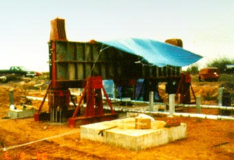
FIGURE 22. Load testing of large model spread footing.
2.9.2 FHWA Staff Research on Spread Footings
- A series of smaller model load tests was concurrently
conducted at TFHRC to evaluate the effects of a high water table, depth of
embedment, size and shape effects, and the use of geosynthetic reinforcing
elements within the sand beneath the footings (see section 3.5.3 for complete
details). A total of more than 100 model footings was instrumented and load
tested to failure. The test data were added to the data base (see section
5.2.2). All of the footing load tests were performed by following the
ASTM Guidelines (D1194-72-1993).
A minimum of five nuclear density and moisture content readings were
taken at each 0.3-m lift of sand during placement operations to characterize
the soil fill. After filling the test pit, in-situ soil tests were done to
complete the soil characterization work.
Results show that embedment has a very significant positive influence
on the performance of footings of the same size, even when the water table
is close to the bottom of the footing. Placement of the footing base at a
depth equal to the width of the footing increases the ultimate bearing
capacity by three to five times the value of a footing resting on the ground
surface.
The depth of the water table also affects the ultimate bearing capacity of the
footing. Those footings resting on sand with a high water table performed much
worse than those where the water table was lowered some distance below the base
of the footing. Bearing capacity values increased by a factor of two when the
water table was lowered from the surface to a depth equal to the width of the
footing. Also, as expected, the bearing capacity increased with increasing width
of the footing and relative density. A comparison was made between the measured
results of each footing load test and the predicted values for bearing capacity
using the results of each in-situ test (30).
2.9.3 Dynamic Testing of Footings -
At both the TFHRC and Texas A&M University (TAMU) sites, a separate but
coordinated study was conducted to evaluate a novel idea to develop a
dynamic measurement system that can be used to quickly determine a soil
stiffness modulus beneath a footing in order to ascertain if the natural
ground or man-made fill is of sufficient quality to adequately support the
imposed loads on the footing. An NDE test, termed the Wave Activated
Stiffness test, was proposed to be a more efficient, less costly method of
checking for bearing capacity and settlement adequacy than conventional
static load testing or performance observations. These are
"after-the-fact" methods as opposed to the
"before-the-fact" dynamic methods that are done during
construction, just after the footing is built and before loads are
applied.
This nondestructive impact test is called the WAK test for short,
rather than WAS because of the common use of "K" to symbolize
soil stiffness in most design equations, coupled with the fact that the
impact of the instrumented hammer when it strikes the footing sounds like
a loud "whack." The instrumentation consists of a force transducer
attached to the tip of the sledgehammer and geophones placed at the diagonal
corners of the footing to record the footing-soil response to each impact
blow. The force transducer provides the input to the system (impact force)
and the geophones yield its response (velocity of the footing).
The impact of the hammer causes the footing and a bulb of soil
directly beneath the footing to vibrate. The velocity of this vibration is
measured by the geophones. The theory is based on a simplified, linear
system model of the soil-footing assembly. This model consists of a mass, a
spring, and a dashpot, which is frequently used to describe the vertical
vibration of soil-structure systems. The compression wave that travels down
a steel pile when struck by a heavy hammer is another example of this
modeling tool.
Twenty-two WAK tests were conducted at the FHWA TFHRC site and 16 at the TAMU site.
Conventional static load tests were also performed on each footing where a
WAK test was done. All results indicate good agreement between static load
test stiffness and the dynamic stiffness from the WAK test. Each of the
footings was tested four times with the WAK equipment; twice before and
twice after the static load tests were conducted.
A plot of dynamic stiffness results against static
stiffness results for the entire series of footing tests yielded a graphical
relationship that allows one value to be picked off the plot if the other
one is known or determined by testing. Therefore, a dynamic result can be
used to approximate a static stiffness parameter K (which represents the
slope of the initial part of the static load settlement curve) without
actually running an expensive static load test.
The manufactured K value can be used to estimate the supporting capacity during
construction when there is still time to correct any problems. This type of
test can also provide a small measure of comfort to design engineers who fear
that construction operations may not actually provide a solid foundation base
beneath the footing. Such a test will help to identify poor compaction problems
and other possible construction deficiencies that could occur when spread footings
are used in lieu of piles (28).
2.9.4 Publications and Implementation Items
Research and development activities for spread footings were very successful. The research reports documented the testing and evaluation results and presented recommendations and supporting information for using spread footings in lieu of deep foundation elements in situations where foundation soils could safely transmit bridge loadings without damaged settlements resulting. Technology transfer items were developed to inform practitioners about the research findings and new ideas being promoted. The AASHTO Bridge Specifications were revised as a direct result of this research project on spread footings (see chapter 7).
2.10 Foundation Load Testing
During
the past 20 years of bridge foundation testing and evaluation, FHWA
researchers have learned a lot about what works and what doesn't work.
Hundreds of load tests have been conducted at TFHRC by staff personnel, and
hundreds more have been funded by FHWA in field and laboratory projects.
Numerous innovative improvements have resulted from these efforts, which, in
turn, have led to advancements in the testing techniques and in foundation
engineering design and analysis.
All of the early work and most of the later work was done by static
load testing, which is considered by most engineers to be the most reliable
way to determine the bearing capacity and load/settlement behavior of a
foundation element or groups of elements. It is, however, also very time
consuming, cumbersome, and expensive to perform, especially on large
elements or groups. Safety is also an important issue because of the sheer
massiveness of the required loading systems. As previously discussed,
dynamic pile driving methods have become a common alternative to predict the
bearing capacity of piles, but these methods are empirical, their accuracy
varies considerably, and the trend toward much larger and deeper elements
reduces their applicability. Also, they do not provide direct measurements,
they induce high accelerations, and the load/settlement behavior is
controlled by the action of stress waves.
In an effort to overcome the practical difficulties of both conventional static
and dynamic load testing, FHWA initiated a series of research studies to evaluate
several promising load test methods that were developed by U.S. and European
inventors. None of these methods came with sufficient documentation for standardized
test procedures or for the interpretation of data produced by these tests. The
following sections summarize the efforts to evaluate and refine several of these
innovative methods.
2.10.1 Statnamic Load Testing
The term
"Statnamic" is a combination of the two words — "static
and dynamic" — because it was neither one nor the other, but
somewhere in between. Upon closer study it is seen to be closer to being
quasistatic than dynamic, especially now in its latest version where there
is no dynamic impact. In Statnamic testing a high-energy, fast-burning solid
fuel is ignited within a pressure chamber to act as an upward propellant
force. As the fuel pressure increases, an upward force is exerted on a set
of reaction weights while an equal and opposite force pushes downward on the
foundation element. Loading increases until it reaches a maximum, and then
it is vented to control the unloading cycle. Figure 23 schematically
illustrates the statnamic concept.
In the original version the weights would come toppling down on the pile or
shaft after the fuel had completely burned off, and possibly damaged the foundation
element being tested. This problem was solved by placing sand in an outer, concentric
container that allowed the sand to flow downward (while the weights were pushed
up and off the foundation) and cushion the blow from the falling weights (dynamic
impact). The extra time to set up the sand container, and cleanup for retesting
created a different kind of problem that was later solved by the development
of a catch mechanism and the pressure venting system. A calibrated load cell
located between the piston and the pile top is used to measure the applied load
and a photovoltaic laser sensor records displacement during
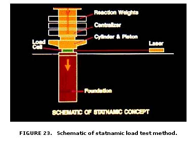
the
test. The assembly and take down is very straightforward. All components are
easily handled with a small hoisting rig. This system is capable of
producing a given force or load using only 5 percent of the mass required in
an equivalent static test. The original development in 1988 began with a 0.1
MN test device; however, current test devices are capable of producing loads
up to 30 MN. Furthermore, because the direction of force is along the
cylinder assembly, loading is perfectly axial or horizontal if the apparatus
is shifted 90 degrees to perform a lateral load test. A batter pile test
configuration can also be adopted if desired. The relatively slow
application and release of compressive forces eliminates negative tensile
forces, compressing the pile and soil as a single unit.
Throughout loading, load and displacement
signals are digitized and sent to a raw voltage data file. After the event,
the raw signal voltages are converted to load and displacement values using
factory calibration values. Load-displacement graphs are presented
immediately to on-site engineers for quick evaluations. Supplementary graphs
of velocity and acceleration versus time can also be generated with simple
post-processing commands. All data are stored for future analysis and
reference.
During the 1990's FHWA has performed or funded many Statnamic tests and correlation
studies with conventional static load tests to develop standardized testing
procedures and improved data interpretation methods. Many SHA's and other domestic
and foreign agencies are now conducting their own evaluation programs to further
expand the data base of case histories and performance studies. Measurements
made with the Statnamic device owned by FHWA compared very well with static
load tests performed by TFHRC researchers on spread footings and pile groups
in the research test pits (see appendix A). Measurements on full-scale piles
and drilled shafts on other FHWA sponsored research projects have also compared
well with static load test results. Figure 24 shows a test at FHWA's foundation
load test facility.
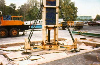
FIGURE 24. Vertical statnamic load test on model pile group at TFHRC.
In late 1996, FHWA participated in a research program with the Utah DOT on a major rebuilding project on I-15 in Salt Lake City. The research involved the lateral behavior of a nine-pile group that was tested in both a free and fixed head condition. A 14 MN device was used on the fully instrumented group. FHWA also funded a similar test program at the Auburn University NGES during the same time period (see chapter 5).
2.10.2 Osterberg Cell Load Testing
The Osterberg Cell is another innovative technique that has been evaluated by
FHWA during the 1990's to determine its applicability and potential
for reducing time and costs of performing foundation load testing,
especially for drilled shafts. The drilled shaft designer must face both the
problems of predicting subsurface soil and rock strength and compressibility
characteristics, and the difficulty of estimating the impact of construction
installation technique on the completed shaft. Model testing and laboratory
investigations don't provide sufficient insight to assess the complex
interaction between soil (especially intermediate geomaterials) and the
concrete shaft. The Osterberg Cell, commonly called the "O-cell",
is well suited for this problem and has provided an attractive short
duration alternative for testing drilled shafts (31).
The O-cell is a hydraulically driven,
high-capacity sacrificial jack-like device that is installed at the bottom
of the reinforcement cage (figure 25) of a drilled shaft or at the tip of a
driven pile. Unlike the conventional static and dynamic load tests that
apply a
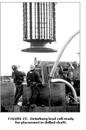
compressive force at the top of the pile or shaft,
the O-cell loads the unit in compression, but from its bottom end.
It requires no overhead reaction frame, dead load, or other external
system. As the O-cell is pressurized and expands, the shaft and
the soil provide reaction to the applied loads. The end bearing
support provides reaction for the side friction along the shaft,
and vice versa, until reaching the capacity of the cell or either
of the two support components. O-cell tests automatically separate
the end bearing support component from side friction values. Thus,
an O-cell test load placed at the bottom of the shaft has twice
the testing effectiveness of that same load placed at the top of
the shaft. Production shafts can also be tested, if the device is
grouted after testing is completed.
Movements of the foundation element during an O-cell test are measured
by electronic gauges connected to a computerized data acquisition
system. Linear vibrating wire displacement transducers (LVWDT's)
are attached to the bottom plate of the O-cell. Telltales are used
to measure both the compression of the test pile and the upward
movement of the top of the O-cell. The downward movement of the
bottom plate is obtained by subtracting the upward movement of the
top of the O-cell from the total extension of the O-cell as determined
by the LVWDT's. The upward movement of the top of the test pile
or shaft is measured by digital gauges mounted on a reference beam.
The loading mechanism has evolved from the original bellows-type
expansion cell to the current piston-type jack. However, the piston
extends downward instead of upward like that of a conventional load
test.
The O-cell test offers a number of obvious advantages over conventional
load testing, including economy, high load capacity, safety, reduced
work area, and the ability to separate the end-bearing and side-friction
components. Disadvantages include the need for advance installation,
sacrificial expendability, unsuitability for certain types of piles,
and the balanced component limitation, i.e., the test capacity is
limited to twice the capacity of the support component reaching
ultimate first. It has been noted that the majority of load tests
on drilled shafts are now being done with the O-cell.
Boston Engineers were the first to use the O-cell in a practical
application in 1987 on a bridge site near Boston, Massachusetts
and later that same year at Rochester, New York. After testing,
they recovered the cell and used it on another test site. In 1988,
two more tests were performed with FHWA research funds at a bridge
in Port Orange, Florida. More than 200 additional tests have been
performed with O-cells in the United States on piles and drilled
shafts during the 1990's, including some lateral load tests.
The Minnesota DOT recently completed a major load-testing research
program featuring the use of O-cell devices in both axial and lateral
load-testing modes. The shafts were 58 m deep and 1.3 m in diameter.
One of the test shafts was instrumented with Sister Bar strain gauges
to develop a better understanding of the load transfer distribution.
The first-ever embedded O-cell lateral load test was on a second
test shaft on this same project.
Other interesting applications in FHWA-sponsored projects include
two previous record- setting performances in Massachusetts and Kentucky
on highway bridge projects. The Owensboro, Kentucky record of 53.4
MN (6000 tons) was soon broken by the Boston Central Artery project
record of 55.9 MN (6,280 tons), which was easily broken by the Florida
project. The site conditions on Boston's Southeast Expressway (I-93)
were treacherous because the test shaft was drilled between the
two fast lanes inside two jersey barriers only 2 m apart. The testing
was completed without obstructing or disrupting traffic flow.
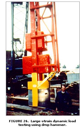 No
job appears to be too big or too small for the use of an O-cell. Several
world records for load testing have been set recently, including the current
world record for total load of 135 MN (more than 15,000 tons) set in Florida
in 1997. Whether inside a building or under a bridge with limited access
or low headroom, or within a cofferdam in the middle of a river, O-cell
testing can perform well. It can be used to isolate portions of a pile
or shaft by installing multiple cells, and is fast becoming a favorite
of engineers and contractors because of its speed of installation and
cost advantages.
No
job appears to be too big or too small for the use of an O-cell. Several
world records for load testing have been set recently, including the current
world record for total load of 135 MN (more than 15,000 tons) set in Florida
in 1997. Whether inside a building or under a bridge with limited access
or low headroom, or within a cofferdam in the middle of a river, O-cell
testing can perform well. It can be used to isolate portions of a pile
or shaft by installing multiple cells, and is fast becoming a favorite
of engineers and contractors because of its speed of installation and
cost advantages.
2.10.3 Dynamic Drop Weight Load Testing
The use of a heavy weight (90 KN) falling from various heights (0.3 to 5 m) is another method to predict the load capacity of a pile or drilled shaft (figure 26). The foundation element is instrumented with strain gauges and accelerometers to measure the force and impact velocity of the stress wave generated by striking the element. The measured data are correlated to driving resistance to predict load capacity. An electric theodolite is used to measure the settlement associated with each hammer blow. The friction in the hammer leads
and the cushion assembly cause the actual energy delivered to the pile or shaft to be much less than the free-fall energy of the ram. This is accounted for by the instrumentation gauges similar to the Pile Driving Analyzer equipment used during pile driving operations to monitor resistance to driving. A service crane is required on site to perform the tests.
Three different methods (one U.S. and two European ) were evaluated on several FHWA research test sites to determine the applicability of this type of testing to check pile or shaft capacity. The GRL method was developed at Case Western Reserve University in Cleveland, Ohio, by the same people who developed the PDA, WEAP and CAPWAP. The "SIMBAT" method was developed by the French government's Center for Experimental Research on Buildings and Public Works (CEBTP). The TNO method was developed by the Dutch government at their national research center in the Netherlands. The Europeans have amassed a large data base of static/dynamic test result correlations. As a result, these methods have become established practice in several European countries, but have been slow to catch on in the United States because of the greater success of the O-cell and statnamic methods. Also, test results on FHWA projects have not measured up to expectations thus far, usually over-predicting the measured capacities. Further investigation is planned to complete the evaluations.

