U.S. Department of Transportation
Federal Highway Administration
1200 New Jersey Avenue, SE
Washington, DC 20590
202-366-4000
Federal Highway Administration Research and Technology
Coordinating, Developing, and Delivering Highway Transportation Innovations
 |
| This report is an archived publication and may contain dated technical, contact, and link information |
|
Publication Number:
FHWA-RD-98-139
|
Relatively few options are available in choosing the ground
materials and site conditions that must be accounted for in the design of highway projects.
The project must be constructed under the conditions that are present at the particular site;
minimal disturbance to existing elements of the roadway is also a key control factor in the
selection and design of the rehabilitation or reconstruction scheme. For example, the
widening of existing roadways or bridges requires that the selected technique be one
that can deal with the problem soil condition effectively, and also cause minimal
damage to the existing facility.
This is especially true for roadway widening projects in areas of very soft foundation
soils. If the existing embankment was placed in an excavated trench where the unsuitable
material was removed, the same construction technique will cause serious problems because
excavation adjacent to the existing embankment will jeopardize the stability of the
existing facility. In those cases where the foundation soil is not removed, the pressure
of the widened embankment causes significant differential settlements if the soft soil
is not reinforced or otherwise strengthened.
The problem of economically constructing and maintaining stable slopes within limited
right-of-way is a continuing concern. Where increasing traffic requires the addition
of lanes within the same right-of-way, costly conventional earth retaining structures
are often necessary. Such structures are also required where existing or proposed
slopes are unstable and flattening of the slope is not feasible.
In urban areas where depressed freeways are to be widened or in rural areas where
large cut slopes are to be reopened, the slope excavation can become a very difficult
and expensive engineering problem to resolve. Innovative methods to stabilize or
otherwise strengthen the existing slope prior to excavation must be identified and
evaluated to increase the available inventory of design approaches that can be used
to solve these particular problems.
In recent years, some of the most noteworthy advances in geotechnology have been in the
area of earth reinforcement. Powerful, innovative techniques have been initiated and
are still being developed here and abroad that have the potential for improving stability
at reasonable cost. However, it should be noted that throughout their short history,
commercial and technological innovations in ground improvement technology have almost
always preceded research studies of fundamental performance and the development of
engineering guidelines. Examples include: reinforced earth, micro piles, tieback
anchors, and soil nailing. Some of the techniques under study were proprietary,
and information on many of the innovative methodologies was not widely distributed.
Therefore, there was an urgent need to collect, evaluate, and disseminate the current
state of the art on their use and applicability.
To encourage widespread use of these systems, two pressing questions needed to be
answered: (1) What new systems were available? and (2) Where will they provide
satisfactory performance at a cost savings over conventional methods?
In the past, conservative thinking in the highway field hindered innovative development
and cross-fertilization of special ground improvement techniques between the United States
and foreign countries, particularly western Europe and Japan. Innovations from these other
countries have fostered major changes in the United States in many areas of ground
improvement and earth retention systems. These changes have occurred in both our
approach to design and construction activities. They are good examples of how foreign
innovations have shaped U.S. practice.
3.1 Background
At the time this research project was initiated, hundreds of miles of existing highways were scheduled to be reconstructed or upgraded in areas where difficult soil and foundation conditions would be encountered. In many cases there was considerable pressure applied to minimize the disruption to traffic flow, and to select courses of action that did not require destruction of or harmful effects to existing pavement systems or structural facilities such as bridges and retaining walls that still had a long useful life remaining.
Ground improvement techniques were found to provide benefits in the following five major areas:
Recent developments (at the start of this research project) in Europe and Asia had shown great promise in providing cost-effective solutions to difficult soil and site improvement projects that heretofore were unavailable or extremely expensive to resolve. Many of these developments were reported to save large sums of money when used in lieu of conventional solutions; however, documented evidence of the actual savings as well as the mechanics of how the particular system worked was usually not available or very difficult to obtain. As a result, an accurate estimate of the potential benefits was impractical or very difficult to make; however, preliminary estimates indicated a very high rate of return on research expenditures was very likely to occur.
3.2 Objectives
The objectives were to identify and refine existing ground improvement techniques that can be used to stabilize or reinforce soil or rock masses that provide support for roads and structures. Design and construction guidelines were to be developed to reduce costs associated with providing adequate ground support for pavements, bridges, and retaining walls.
3.3 Scope
Research and development efforts in this project
were directed toward analyzing and improving existing techniques for reinforcing
and strengthening ground masses supporting or otherwise impacting highway facilities.
The development of new techniques to replace or supplement existing techniques was
also considered where appropriate. The utilization of ground improvement methods
for the design and construction of new highways was covered; however, the main
emphasis was on the bridge rehabilitation/replacement program and the roadway
restoration program.
This project included all materials and methods to reinforce, stabilize, or
otherwise improve soil and rock masses used to support highway structures.
The project evaluated the basic mechanisms underlying each technique and developed
rational design and construction methodologies for each appropriate technique.
Design guidelines were developed for each technique and included the selection of
design values and the determination of geotechnical design parameters, specifications
and special provisions, and system geometrics such as spacing, depth of treatment,
equivalent diameters, sizes, shapes, and weights. Other engineering considerations,
such as effect of groundwater table location, energy attenuation with depth, effective
compaction depth, and types of soils most suitable to each type of improvement technique,
were also studied and appropriate guidance was provided.
Construction guidelines, including construction control and performance monitoring
methods, were also developed for each technique. Units of measurement and payment
and end product evaluation techniques were also developed and presented in a
guidelines format.
Although the main emphasis was on existing techniques rather than developing new
techniques, it should be noted that many of the existing techniques evaluated were
very new and still in their infancy in terms of technical development and implementation.
Some of these methods demonstrated significant savings over conventional methods and
showed great promise for even larger cost savings when improved guidelines were
developed under this program.
3.4 Project Description
The major research efforts were in two tasks:
3.5 Soil Reinforcement
Inclusions have been utilized since prehistoric times
for the improvement of soil. The use of straw to improve the quality of adobe bricks
dates back to earliest human time, when many primitive people used sticks and branches
for reinforcement of mud dwellings. During the 17th and 18th centuries, French
settlers along the Bay of Fundy in Canada used sticks for reinforcement of mud dikes.
Some other early examples of man-made soil reinforcement include dikes of earth and
tree branches, which have been used in China for at least 1,000 years and along the
Mississippi River in the 1880's. Other examples include wood pegs for erosion and
landslide control in England, and bamboo or wire mesh, used universally for revetment
erosion control. Soil reinforcement can also be achieved by plant roots.
Retaining walls are an essential element of every highway design. Retaining structures
are used not only for bridge abutments and wing walls but also for slope Stabilization
and to minimize right-of-way required for embankments. Not many years ago retaining
walls were almost exclusively made of reinforced concrete, and were designed as
gravity or cantilever walls. Such walls are essentially rigid structures and cannot
accommodate significant differential settlements. With increasing height of soil
to be retained and poor subsoil conditions, the cost of reinforced concrete retaining
walls increases rapidly.
Reinforced soil walls and slopes are cost-effective soil retaining structures that
can tolerate much larger settlements than reinforced concrete walls. By placing
tensile reinforcing elements (inclusions) in the soil, the strength of the soil
can be improved significantly such that the vertical face of the soil/reinforcement
system is essentially self-supporting. Use of a facing system to prevent soil
raveling between the reinforcing elements allows very steep slopes and vertical
walls to be safely constructed. In some cases, the inclusions can also withstand
bending or shear stresses, thus providing additional stability to the system.
At the time of this research, there were no uniform standards for these systems,
and in fact, there were different design and construction criteria and procedures
for each system. Moreover, each of these systems had a different performance record.
Research under this project identified and evaluated various reinforcement methods
such as tensile, compressive, and shear force resistance elements that are inserted
into the soil mass to improve bearing capacity and/or settlement characteristics.
The evaluations included all materials and methods to reinforce soil masses.
Studies were undertaken to evaluate the basic mechanisms underlying each technique,
and rational guidelines for design and construction of each technique were developed.
Each technique was evaluated by reviewing the literature, and discussing the
performance of particular case history examples with design and construction
engineers, plus specialty contractors involved in using these innovative techniques.
Subsequent studies involved soil characterization and reinforcement material
evaluations to determine appropriate parameters for design and construction control.
Small-scale laboratory model and also centrifuge model studies were conducted for
those techniques that required further refinement and verification. Full-scale
field testing and construction monitoring studies were also done to validate some
of the research findings from the initial investigations.
3.5.1 NCHRP Benchmark Study - The FHWA research program in soil reinforcement was based on the results of a major NCHRP study that performed an extensive literature review and evaluation of available systems and design methods (NCHRP Publication 290). That state-of-the-art report provided in-depth background on soil reinforcement for engineers seeking an understanding of this important, and at that time, new subject.
3.5.2 Reinforced Soil Structures -
The NCHRP study was expanded by FHWA to examine the design, construction, and
performance aspects of a selected few of the mechanically stabilized earth systems
identified in Report 290 for use in retaining structures and excavation support
systems. The main purpose was to develop guidelines for these systems to provide
highway engineers with guidance for selection, design, and construction of the
selected systems in a generic manner.
The study was performed by reviewing and evaluating several existing methods in
terms of field experience, laboratory testing (including centrifuge studies), analytical
studies, and a full-scale field evaluation program (figure 27). The results were then
used to develop and substantiate the generic design procedures and other guidelines
presented in the manual (32). Volume 2 contains a technical summary of the research
supporting theory to verify the design theory in Volume 1, plus information on several
proprietary reinforced soil systems (32).
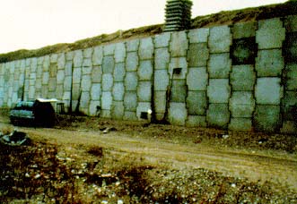
FIGURE 27. Reinforced soil test wall.
The manual has become a valuable tool to assist highway engineers and others in determining the feasibility of using reinforced soil systems for walls and embankment slopes on a specific project, evaluating different alternative reinforcement systems, and performing preliminary design of simple systems. The manual also provides a basis for evaluation and preliminary design of new earth reinforcement systems that may be proposed in the future.
3.5.3 Reinforced Soil Foundations (RSF) -
A staff study at TFHRC investigated the use of geosynthetic reinforcing elements beneath
spread footings to create a composite material with improved performance characteristics
to determine if this method of ground improvement is applicable to bridge support.
Information was obtained on how to quantify the improvements and optimize the location
of the reinforcement in the soil below the footing. The results of this study proposed
an optimal size of an RSF using soil strain signatures and normalized settlement criteria.
Model load test results on 34 footings describe the optimal depth and reinforcement layering
within an RSF.
One of the first tests conducted was on a spread footing placed at the surface on an
unreinforced compacted sand that was load tested to failure (figure 28). Both the footing
and surrounding soil were fully instrumented to map the distribution of soil strain beneath
the footing. The map was used to describe the complete mode of soil failure, and clearly
defines the zone of maximum soil displacement. The identity of this zone within the engineered
fill pin pointed where the geogrid should be placed for optimum reinforcement in the next
series of tests.
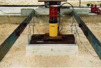
FIGURE 28. Spread footing load test on reinforced soil foundation.
The next series of tests was conducted to evaluate the
relationships between the layering of the reinforcement to the width (B) of the spread
footing. Two series of load tests were performed on four different sizes of square
footings (0.3 m, 0.45 m, 0.6 m and 0.9 m) on the sand surface to measure the settlement(s)
of the footing at various loads.
The next tests were performed to compare the performance of Reinforced Soil Foundations
(RSF's) to the unreinforced footings with various embedment depths (D) to determine the
best features of each approach to increase bearing capacity. For example, a spread
footing embedded 0.5 B was compared with a one-layer RSF placed at 0.375B beneath the
base of a surface footing. An embedded footing with a D/B of 1.0 was compared with a
three-layer RSF placed at 0.25B, 0.5B and 0.75B below the surface footing. The test
results were used to calculate bearing capacities at various D/B ratios.
Vertical displacements within the sand below the footings were measured by telltales
located at various depths below the four corners of each footing. Horizontal strains
were measured by inclinometers located at 0.25B and 1.0B outside the footing footprints.
Linear Variable Differential Transducers (LVDT's) were used to measure settlement at the
top of each footing for each load increment that was measured by load cells between the
footing and loading jacks. Footing settlement, vertical soil displacements below the
footing, and horizontal displacements to the side of each footing were measured at each
load increment.
As expected, the data show that soil deformation occurs first in the upper layer of
sand just below the footing and propagates to deeper areas with increasing load,
following a pattern that can be clearly seen in any standard soil mechanics text.
What is not shown anywhere else besides these tests, is the well-defined strain
signature that clearly shows that almost all soil deformation occurs within a zone
of 0.5B beneath the footing, rather than 1.0 to 2.0B, as proposed by previous researchers.
Because the data show that the upper layer undergoes the highest strain during the
early part of the load test, it is recommended to place a layer of reinforcement in
this zone of initial strain, and a second layer in the lower zone of maximum strain.
The telltale measurements clearly identified the higher zone to be at 0.125B, and
the maximum zone at 0.375B. Placing a layer of reinforcement at these levels will
significantly improve the load settlement performance of surface or shallow depth
footings on sand. If only one layer is required, it should be placed at the point
of maximum strain, which is approximately at the 0.375B level. It was also noted
that, when the reinforcement was placed in the zone of maximum soil shear, it acted
to significantly inhibit the development of a classical bearing capacity failure.
The zone of horizontal displacement is mostly within a distance of 0.5B beyond the
edge of the spread footing. This means that the reinforcement doesn't need to extend
more than 0.5B past the edge of the footing on all sides. The imprint area of the
reinforcement is therefore required to be four times the size of the footing imprint.
In many tests comparing surface footings on sand to surface footings on an RSF, the
ultimate bearing capacity of the RSF was twice the value of the conventional footing.
The performance of an RSF was shown to be very comparable to the positive effects of
footing embedment. The knowledge gained during these experiments was put to immediate
use for design of the RSF to support the geosynthetic reinforced soil bridge pier
described in section 3.5.4.1 of this chapter.
A review of the literature indicates that this study was the largest of its kind, both in
terms of number of footing load tests performed and size of footings tested. The results
clearly demonstrate that geosynthetic reinforcement can substantially increase the bearing
capacity of shallow spread footings on sand and can reduce the amount of settlement,
especially differential settlement of the four corners of footings. The footings
resting on unreinforced sand settled unevenly, while those on reinforced foundations
settled very evenly with no tipping of the corners. Additionally, the footings on a
RSF were more likely to experience a gradual failure curve rather than a plunging
failure (30).
3.5.4 Geosynthetic Reinforced Soil Structures -
The use of geosynthetic grids and sheet materials to reinforce soil layers in walls, abutments,
and piers to support highway structures has increased significantly in the 1990's due to cost
advantages and freedom from worry about corrosion and durability issues. Similar to the
rapid increase of other ground improvement technologies, expanded usage has preceded the
development of rational technical guidelines and fostered significant debate over several
technical issues, such as vertical spacing of reinforcement layers, connection issues,
compaction details, facing cracks, soil fill specifications, seismic response, scour
protection, pre-straining requirements, and optimal applications. It is also necessary
to determine optimum base to height ratios, including appropriate limitations and design
criteria, plus lateral load resistance factors.
FHWA developed an in-house staff project to answer these unanswered questions. The first
phase of the study involved the construction of a full-scale bridge support pier out of
polymer based fabric sheets, road base gravel, and regular home building cinder blocks
(figure 29). The pier was constructed at the TFHRC campus to facilitate construction
supervision and monitoring of the research testing. It was built on a reinforced soil
foundation platform that was placed approximately one meter below natural grade.
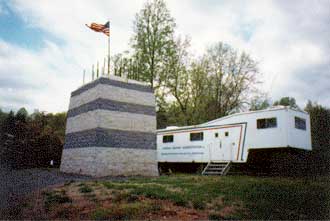
FIGURE 29. Geosynthetic reinforced soil support pier.
A series of model piers was also built and tested to supplement the results of the full-scale tests. These smaller piers were much faster to construct and easier to test to failure than the prototype, which permitted the researchers to vary different parameters to evaluate the effects of certain changes on overall performance. Another series of full-scale tests on the prototype and several larger full-scale structures is planned for the 1999 construction season.
3.5.4.1 Full-Scale Pier Project -
The bridge support pier was built to a height of 5.4 m and was 3.6 m x 4.8 m at its base,
with a slightly smaller top area due to an inward tapering effect for aesthetic purposes.
The pier was fully instrumented to monitor load, vertical settlement, lateral deformation,
and internal creep and strain in the reinforcing fabric.
A thin concrete leveling pad was used beneath the facing blocks to ensure a proper start
and level rows of blocks throughout the entire height of the pier. Six concrete reaction
pads were placed on top of the support base and inside the facing block perimeter. Four
steel rods were anchored in each reaction pad. They were designed to be extended through
the full height of the pier and attached to a similar set of six reaction pads to be placed
at the top of the pier and matched to the bottom pads. The steel rods were isolated from
the internal soil mass to preclude any vertical reinforcement contribution from the rods.
The reaction pads and connecting steel rods were needed to apply squeezing loads for testing
purposes, and were designed not to interfere with normal functioning of the pier.
A high-strength, woven polypropylene geosynthetic made by Amoco (#2044) was used to
reinforce a well-graded gravel material that is routinely used beneath highway pavements
in Virginia. The cinder blocks were dry stacked and served as a construction form as
well as a facing block for the gravel during compaction operations. The fabric was
placed at each layer of block and gravel, with no special connection features except
to overlap the fabric between each layer of blocks. No gluing or pinning was used to
secure the fabric to the blocks.
At the mid-height of construction, the top reaction pads were placed and reaction beams
were attached to the steel rods to squeeze or pre-strain the composite soil mass using
heavy duty loading jacks. Load cells, LVDT's on top and on the sides, and a laser
measurement system were used to monitor stress and strain responses to the squeezing
process. The pre-straining operation served to eliminate most of the expected
post-construction settlements, and enhanced the composite nature of the reinforced
soil mass because the key to the composite feature is the denseness of the soil
and the bond connection between the fabric and the compacted soil.
The vertical spacing between reinforcement sheets plays a major role because the
composite feature is greatly diminished when separation distances between reinforcement
layers become too large. The optimum spacing issue was further studied under the model
test investigation. The contribution of the facing blocks is also under investigation.
In addition to the facing aesthetics, soil raveling and erosion control, and construction
form work during compaction, there is a good possibility that the blocks make a
significant contribution to the composite feature of the reinforced mass.
The size of the reaction pads and the number of steel rods were far greater than
necessary to provide sufficient pre-straining during the construction process at
the mid-point (or one-third point if deemed appropriate) and completion of the
full-height pier. The extra reaction capacity was installed to provide sufficient
capacity for research load testing purposes. No rods or pads would be needed if
pre-straining was not considered important to ensure bearing capacity and settlement
control. For this design, only about half the available capacity would have been
required if load testing to failure was not in the plans, and pre-straining only
was desired.
At full-height construction, the pier was again subjected to pre-straining. The same
stress and strain type measurements were taken, plus creep and strain measurements were
made on four layers of fabric installed in the top half of the pier. A total of 21
strain gauges was installed on each of the four layers. The measured strain along
each fabric layer was uniform, indicating the load was applied evenly over the pier area.
The pier was later load tested to a much higher level than the pre-straining levels
(but less than complete failure load) to determine near upper bounds on bearing
capacity and settlement values for this particular composite mass. The loading was
stopped when severe cracking, bulging, and displacement of the facing blocks occurred,
but not before load and displacement measurements demonstrated how strong and capable
this system is for support of heavy bridge loads without significant deformations
resulting. Maximum loading conditions were not applied in order to preserve the
structure for additional testing; however, total collapse failure loads were imposed
on the smaller scale models discussed later.
The FHWA manual, Mechanically Stabilized Earth Walls and Reinforced Soil Slopes
Design and Construction Guidelines, recommends that bridge loads on this type of
structure not exceed 200 kPa (2.1 tsf). At this loading level the performance of the
pier was very good. Lateral deformation and vertical settlement were very small and
no cracks or other signs of distress occurred in the blocks. Performance also
remained good at much higher levels than the not to exceed limit specified in
the manual.
The connection strength issue did not seem to be a problem in this situation.
The connection consisted of a frictional bond between the blocks and the fabric,
with no glue or fasteners used to enhance the connection. Results show that none
was needed. The vertical squeezing forces that were applied to the soil and fabric
mass seemed to cause a "drag" type of force to be applied to the blocks
as the reinforced soil mass was forced to consolidate. Compression cracks occurred
as the drag forces reached higher levels; however, the connection issue was not
adversely affected.
The overall experiment was very successful and served to increase our knowledge of
how this type of structure can best be utilized to provide safe and efficient support
for highway bridges, especially in remote areas where concrete and steel are expensive
to haul to the bridge site, and heavy equipment is hard to mobilize. This concept may
also be a good alternative in seismic areas because each layer of gravel and
reinforcement may serve as a force-dampening shock absorber between the
earthquake-generated ground motions and the bridge superstructure (33).
3.5.4.2 Model Studies - At another site on the TFHRC campus, a series of smaller scale models of the prototype pier were built and tested to failure. The same type of block was used to build the models except that the fabric was not placed to overlap the blocks, and the blocks were removed before testing. A base height ratio of 0.5 was used to provide similitude with the prototype. The same gravel material was used; however, the same geosynthetic reinforcement material was used in only a few of the models at various vertical spacing distances to investigate the effect of distance on the composite mass performance under extreme loads. A lesser strength fabric was also tested at varying spacing distances (33).
3.5.5 Corrosion and Durability -
One of the major design concerns for reinforced soil structures has been the corrosion
or durability of the reinforcing elements in the soil/water environment in which they
are placed. In the early days of building reinforced soil structures in the United
States, the material of choice was almost exclusively metallic, either in strip or
grid configuration. Galvanized steel worked best, and after a short trial period
the use of aluminum and stainless steel was discontinued due to very poor performance.
Concern about corrosion of the galvanized steel prompted some engineers to try geosynthetic
polymer materials as a reinforcement alternative; however, similar durability concerns
soon became apparent because of the lack of information on degradation factors, such
as hydrolysis and oxidation phenomena, that might occur in the soil/air/water
environment below ground.
To assist engineers in designing new projects and evaluating existing walls,
FHWA performed a series of comprehensive research studies to investigate the
corrosion potential of metallic reinforcing elements and polymer degradation
as related to the design life of the reinforced soil structures. The durability
research included an analysis of the principal aging factors to determine the
extent of decomposition that typically occurs in a soil environment. Other topics,
such as installation damage, biological and environmental attacks, and creep damage,
were also investigated.
 Two reports were issued that describe the corrosion process and provide guidance
and criteria for evaluating potential corrosion losses when using coated or
uncoated steel reinforcing elements. Remote electrochemical measurement equipment
called a PR Monitor was also developed to monitor corrosion potential and in-situ
corrosion rates of base or galvanized steel reinforcements on both new construction
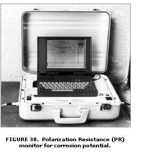
or existing walls. The PR Monitor (figure 30) measures the polarization resistance
(PR) of a corroding interface because the corrosion rate is inversely proportional
to the PR (34,35).
Two reports were issued that describe the corrosion process and provide guidance
and criteria for evaluating potential corrosion losses when using coated or
uncoated steel reinforcing elements. Remote electrochemical measurement equipment
called a PR Monitor was also developed to monitor corrosion potential and in-situ
corrosion rates of base or galvanized steel reinforcements on both new construction
or existing walls. The PR Monitor (figure 30) measures the polarization resistance
(PR) of a corroding interface because the corrosion rate is inversely proportional
to the PR (34,35).
Several reports were also disseminated under the study,
"Durability of Geosynthetics for Highway Applications", that describe the
hydrolytic and oxidative degradation processes, installation damage patterns, and
creep concerns of polymer reinforcements. These reports, plus others in the
publishing process at the time of print for this summary report, provide guidelines
and testing protocols for calculating the appropriate strength reduction factors for
use in design life predictions (36,37,38). Some of the important findings are
discussed next.
On the basis of the data thus far, it appears that most geosynthetic products have
the durability needed for critical reinforcement applications, especially in
relatively neutral soil environments. In severe environmental conditions, results
indicate a fairly wide range of degradation rates. A test protocol for long-term
durability performance testing of geosynthetics (i.e., oven aging and immersion testing)
has been developed, along with an analytical model for service life prediction of geosynthetics.
Variations in the test protocols used to chemically characterize polymers, with
specific reference to geosynthetics, which could significantly affect test results
or make test results difficult to interpret, have been identified and corrections
to the protocols were made. These protocol variations help to explain why comparison
and use of data provided in the literature are difficult.
From the effort to better define the testing protocols, preliminary standardized
test and QC/QA procedures to be applied industry-wide have been developed. This
has set into motion the ability of the industry to perform the tests that will
likely be recommended for future evaluation of geosynthetic durability, and the
ability to develop a consensus on how those tests should be performed and quality
control maintained.
The polymer and soil environmental factors that affect the geosynthetic degradation
rate have been identified as well as tests that can be used to assess and quantify
these factors. The study has also identified the issues that must be addressed to
develop life prediction models for geosynthetics, especially with regard to relating
the laboratory environment to the in-soil environment. A technology transfer report
was developed by FHWA's Office of Technology Applications to assist practitioners in
implementing the new guidelines (39).
A separate but parallel effort by Transportation Research Board (TRB) committee A2K07
has been initiated to develop the framework necessary for rapid implementation of the
results of this study. This effort has also helped to identify just where the real
needs in terms of geosynthetic durability knowledge are so that a coherent recommended
practice to determine the long-term strength of geosynthetics can be developed.
The study has created an environment that has promoted improved communications within
the industry, in particular their polymer experts and suppliers, and with the portion
of the engineering community that routinely uses geosynthetics. This has allowed the
geosynthetic industry to better understand the needs of those who use geosynthetics
regarding durability issues, and has helped geosynthetic users to know what questions
to ask and what can be realistically expected from the industry. A team spirit
between the industry and geosynthetic users, which was not present before the study
began, has begun to develop.
3.5.6 Permanent Ground Anchors (Tiebacks) -
Permanent ground anchored wall systems, often called tieback walls, use tensile elements
anchored in the ground to support earth retaining structures or stabilize landslides.
These walls are built in excavated cuts from the top down. Other highway applications
include bridge abutment underpinning when an end slope under an existing bridge is
removed to permit widening of the roadway; and the strengthening of existing earth
retention structures that have deteriorated because of corrosion or require additional
support for increased loading situations.
Temporary ground anchors were the first system to be introduced in the United States to
support excavations while the permanent facility was being constructed. Soon, however,
these temporary measures gained wide acceptance because of economic and safety aspects,
and they gradually became attractive as permanent solutions. The economy results from
elimination of temporary support systems and reduced right-of-way considerations; safety
is improved by eliminating cramped excavation work areas that are cluttered with
delicate bracing.
Permanent ground anchors are relatively new geotechnical elements that were developed to
a large extent by specialty contractors who had developed their own methods of design and
installation. Many of these methods were proprietary or closely guarded family secrets.
SHA design provisions were viewed by ground anchor contractors as unnecessarily
conservative and restrictive, which increases construction costs.
At first there was much concern on the part of highway engineers because of a perceived
lack of rational design procedures, construction methods, and documented performance
experience. In response to this need, FHWA researchers initiated a contract research
study to investigate this technology under experimental conditions to examine stresses
and deformations occurring under typical loading conditions. Results were then used to
develop a comprehensive manual of engineering guidelines and a computerized design
procedure (40).
A series of four model test walls (2 m high and 5 m wide) were instrumented and tested to
failure (figure 31) at the University of Illinois to verify and refine the preliminary
guidelines established in the early stages of the study on the basis of a literature
search and analytical trials. A full-scale wall (10 m high and 60 m long) was also
built to further refine and validate the new guidelines. The full-scale wall
(figure 32) was built at the NGES facility at Texas A&M University. One
section of the wall had only one row of anchors with heavy soldier beams, and
the other had two rows of anchors with smaller soldier beams. Pullout tests of
full-scale, vertically installed ground anchors were also conducted in an adjacent
area at the TAMU clay site (41).
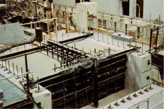
FIGURE 31. Large model ground anchor test wall.
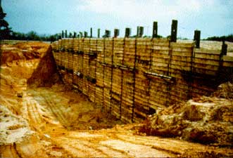
FIGURE 32. Full-scale ground anchor test wall at TAMU NGES.
3.5.7 Soil Nailing -
Soil nailing is an earth retention system that combines short in-situ reinforcements and
shotcrete to support excavations, hillside cuts, depressed cuts, and embankment steepening.
Soil nailing structures are built from the top down in a minimum of space, without temporary
support, without soldier beams, without disruption behind the wall, and less disruption
to traffic and adjacent construction activities. Soil nailing structures can be built
in cohesive and granular soils or in relatively heterogeneous soils with small, easily
mobilized equipment, with less start-up time, and in remote sites. Soil nailing walls
are often the most effective solution to the problems associated with emergency repairs,
vertical cuts close to property lines, projects where drilling costs are high, and
projects with limited access. When used in the proper application, a soil nail wall
can be constructed faster and more economically than most other retaining wall systems.
An in-situ reinforcement technique that improves the soil's overall stability, soil
nailing is constructed with steel reinforcing bars (soil nails) that are usually drilled
and grouted into the ground. Sometimes, other metal tubes or rods are used instead of
bars to resist tensile, compressive, and shear stresses. A relatively large number of
soil nails are installed in a designed pattern that reinforces the earth into a stable
block, which supports the unreinforced soil behind it in a way that is similar to that
of a gravity wall. Soil nailing structures are designed to be both externally and
internally stable. External stability requires that the structural mass be designed
with an adequate factor of safety against sliding, overturning, and bearing failures.
To check a structure's internal stability, most engineers use a method of limit equilibrium
analysis that computes the driving and resisting forces at the critical failure surface.
To further the development and use of soil nailing, FHWA has instrumented many soil nailing
structures, conducted extensive model testing, and thoroughly analyzed prototype walls.
As a result, current designs are more economical and provide for better control of movement.
Construction of a vertical excavation begins with a shallow cut. The height of this cut is
determined by the soil's ability to temporarily stand unsupported, normally about 2 m.
The next step consists of shotcreting the cut and installing the soil nails. Once these
steps are completed, another lift is constructed below the first, and the process is repeated
until the desired level is reached. Drainage is provided to remove water from behind the
shotcrete wall. When soil nailing projects are constructed as retaining walls, construction
follows the same sequence, with the addition of better drainage details and possibly corrosion
protection for the nails.
In nonaggressive ground environments, grout alone provides satisfactory corrosion protection.
When used in more aggressive soils, the steel nail can be epoxy coated to increase its
resistance to corrosion. In most soil nailing applications, the construction of a separate
concrete face is reasonably economical, as well as aesthetically and structurally superior
to the use of shotcrete facing.
Although soil nailing was imported to the United States from Europe with reasonably good
engineering guidelines, there were some major questions concerning the general behavior
mechanisms, failure modes, durability aspects, facing design, and seismic behavior.
A series of research studies was initiated to develop comprehensive technical guidelines
for using soil nailing techniques to stabilize highway slopes and excavations.
The development of a computerized design program was also an important associated
objective of this research.
Analytical studies and physical experiments were conducted to evaluate design parameters
such as type of soil and noncompetent rock suitable for nailed reinforcement; type, size,
and location of reinforcing nails; and design equations for checking stability, internal
pullout resistance, and deformations. Durability aspects were also to be identified and
procedures developed to provide assurances for corrosion protection and structural permanence.
Laboratory tests were conducted to verify the choice of appropriate parameters for
prediction and design. Field tests were then performed on full-scale structures to
verify laboratory and analytical results (42). Figure 33 shows an instrumented nail
being installed on a test wall at the Cumberland Gap tunnel project.
During the course of the soil nailing research project, a partnership with French
researchers was developed to coordinate investigative efforts. The cooperative project
was called "Clouterre", which is French for "soil nail." As part
of the Clouterre agreement, FHWA agreed to focus major efforts on seismic behavior,
field performance monitoring, development of a research quality data base, and facing
design investigations. France placed most of its emphasis on the analysis of the
engineering behavior of soil-nailed structures in different types of soils, including
system behavior and structural displacements. The French researchers
were also responsible for making a critical assessment of available design methods
and special loading conditions, such as frost effects and surcharge loadings, that
occur at bridge abutments.
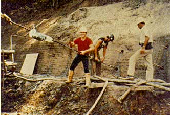
FIGURE 33. Installation of instrumented soil nail at Cumberland Gap site.
A study entitled "Seismic Analysis of Soil-Nailed Retaining Structures"
was initiated under joint sponsorship with the National Science
Foundation (NSF) to evaluate the response and possible failure mechanisms
of soil-nailed walls under dynamic loads. A finite element analysis
and evaluation of the dynamic loading behavior of these walls was
performed using an integral approach consisting of post-earthquake
observations, centrifuge testing, and numerical analysis. The researchers
developed testing procedures to establish reliable design parameters
for characterizing the dynamic soil-nail interaction and formulated
an analysis procedure for the computation of dynamic loading effects
on the location and magnitude of maximum nail forces.
A series of laboratory model tests and full-scale field tests was
previously completed for FHWA to evaluate soil and reinforcement
parameters that are involved in the design and construction procedures
for soil nailing. Data analysis and evaluation of existing procedures
were used to develop interim design and construction guidelines
for using soil nailing techniques to stabilize soil cutslopes.
In a separate research study, FHWA funded a project for "Testing
of Soil Nail Wall Facings" to determine ultimate and service
capacities for developing an appropriate facing/connection design,
especially in regions of high seismic activity. At the time of this
research, the design methods for facings were quite conservative.
Therefore, it was hoped that this research would allow thinner facings
to be used, resulting in construction cost savings. Also at that
time, there was not a consensus regarding which of the available
design methods should be used, because none of the methods were
found to directly apply to soil nail wall facings. The new procedures
are described in the FHWA manual (43).
Another FHWA study investigated the use of soil nails for cohesive
soil Stabilization. A specialized direct shear apparatus was used
to test specimens of the clay reinforced with small-diameter steel
bars (nails) to examine the engineering effectiveness of using soil
nails to stabilize excavations and slopes in clay soils. Proof tests
were conducted initially using sand to verify the performance of
the shear test apparatus, measurement instrumentation, and data
acquisition system. Direct shear tests were then performed on unreinforced
clay specimens to obtain reference data under constant strain rate
loadings before the soil-nail reinforced tests were done. Stresses
in the nails during soil shearing were measured to determine the
nature of nail loading. Existing stability analysis methods for
nail reinforced soil masses were verified and modified to account
for the measured behavior.
A full-scale wall was constructed at the UMASS NGES facility in
Amherst within the varved clay layers of soil in a remote section
of the site. Two rows of nails were installed and readings were
taken from the strain gauges and tip load cells on the nails, plus
the vertical and horizontal inclinometers and piezometers in the
soil behind the wall face. The wall was then induced to fail (figure
34) by excavating below the reinforced portion of the wall to undercut
its stability. Instrumentation readings were taken during the excavation
operations, and at failure when the wall was undercut a total of
2.5 m below the reinforced face of the wall. The field work was
funded by FHWA and ADSC.
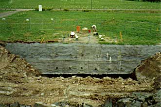
FIGURE 34. Failed soil nail wall due to undercutting.
FHWA and the Washington State Department of Transportation cooperatively funded a study to collect and develop a world-wide data base of instrumented soil nail wall projects. The study also involved using the data base to evaluate existing soil nailing design methods. The data collection and evaluation/validation of the available limit-equilibrium methods provided an improved understanding of the stress-deformation mechanisms in soil-nailed walls, which in turn led to the development of an improved and well-substantiated design procedure for soil-nailed walls.
3.6 Soil Treatment
The primary concern in soil support for structures is
volume stability, strength and durability. However, adequate support is highly variable
and is more case specific than site specific. In the proper state, virtually any soil
type, except highly organic materials, may be adequate for foundation support.
Conversely, any soil type, in its natural state, may be inadequate for foundation
support. Adequate soil support depends more on the loadings and performance
requirements than it does on the soil itself.
The history of soil treatment techniques can also be traced back to ancient times,
like reinforcement technology. During the 1970's and 1980's, several promising
technologies were imported from Europe along with the previously described reinforcement
methods, except that they did not require the insertion of reinforcing elements into
the soil mass. Four of these special methods were selected by FHWA for detailed study
and evaluation to better understand the basic mechanisms underlying each technique;
however, subsequent funding limitations caused the elimination of one of these
technologies (grouting) from the overall program. Research studies were initiated
and completed on dynamic compaction, prefabricated vertical drains, and stone
columns.
3.6.1 Stone Columns - As in most new ground improvement techniques that were developed in foreign countries, experience has preceded the development of theory and comprehensive guidelines. Stone columns have been used since the 1950's as a technique for improving both cohesive soils and silty sands. Potential applications include (1) stabilizing foundation soils, (2) supporting structures, (3) landslide Stabilization, and (4) reducing liquefaction potential of clean sands. The high potential for beneficial use in highway applications prompted a comprehensive investigation to determine how and why the system works so well, and to develop appropriate design and construction guidelines. The guidelines report describes construction, field inspection, and design aspects of stone columns. Also, several case histories are described. Bearing capacity, settlement, and stability design examples are given in the design appendices (44).
3.6.2 Dynamic Compaction -
Dynamic compaction is also a very cost-effective soil treatment technique that can be
used to improve poor subgrade support conditions at a roadway or bridge site. This
is particularly true in or near urban areas where land with good support conditions
has already been developed or set aside for commercial purposes other than highways.
Much of the remaining space is undeveloped land because of poor soil conditions.
In many cases new roads and streets are forced to traverse old landfill deposits,
strip mine spoil areas, or building rubble and construction debris deposits.
Naturally occurring loose sands and collapsible soils such as loess can also present
difficult construction problems for highway engineers. Dynamic compaction techniques
have proven to be ideally suited to handle these problems where other techniques have
failed. Another important application is for densifying loose sands to reduce
liquefaction potential in high-risk seismic zones. Dynamic compaction techniques
have been found to produce densification in natural and manmade deposits to depths
varying from 3 to 12 m below grade.
Dynamic compaction is defined as the densification of loose soil deposits or
miscellaneous fill materials by means of repeatedly raising and dropping a heavy
weight from varying heights to impact the ground (figure 35). This process has
also been called by other names, including impact densification, heavy tamping,
dynamic consolidation, pounding, and dynamic precompression. The energy is generally
applied in phases on a grid pattern over the entire loose or soft area using either
single or multiple passes. Following each pass the craters are either leveled with
a dozer or filled with granular fill material before the next pass of energy is
applied.
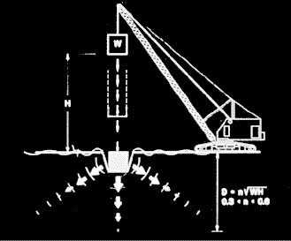
FIGURE 35. Schematic of dynamic compaction methodology.
All of the energy is applied from existing grade, and
the degree of improvement is a function of the energy applied through the mass of the
tamper, the drop height, the grid spacing, and the number of drops at each grid location.
Lighter tampers and smaller drop heights result in shallower improvements. For greater
depths and higher relative density improvements, heavier tampers and higher drop heights
must be used.
When the technology was first imported from Europe, little was known about how to
plan a project or complete a preliminary evaluation to determine if dynamic compaction
is appropriate for the specific site and subsurface conditions. Design details and
construction monitoring guidelines were nonexistent. There were no sample specifications
to guide designers, and no procedures were available to measure the degree of improvement
achieved with each pass. Not knowing when enough is enough can reduce the cost advantages
rather quickly.
To gain more insight, FHWA initiated a contract research study to conduct tests and
evaluation studies of the improvement mechanism to better understand how the technique
worked. A series of field experiments was conducted to investigate soil and tamping
parameters involved in the dynamic compaction process. Instrumentation was installed
to monitor ground vibrations, horizontal and vertical displacements, pore pressures,
acceleration and speed of the tamping weight, penetration of the weight into the ground,
and degree of treatment achieved.
The results of the field tests were used to develop generic specifications and a
manual that describes in detail all of the design and construction issues, plus
all of the non-technical issues previously mentioned (45). The manual was recently
updated by FHWA's Office of Technology Applications and reissued as Geotechnical
Engineering Circular No. 1 to provide this new information to assist SHA's with a
user-friendly engineering document. A slide tape show was also developed to provide
a visual rendering of the manual for instructional purposes.
3.6.3 Prefabricated Vertical Drains -
The need for proper drainage in highway projects is well established. Sand and /or gravel
layers (or other geometric shapes) have been used for decades to provide the appropriate
drainage vehicle. One of the most cost-effective methods of soft ground improvement is
through drainage, especially the use of radial drainage and manmade vertical drains
working in tandem. When heavy embankments are placed on soft depositional type soils,
the loading will tend to squeeze the water out of the soil in a vertical upward
direction to a drainage blanket placed at the bottom of the embankment, and possibly
downward to a natural drainage layer (of sand) that might exist below the soft and
low permeability layer that is being squeezed.
In a soil that has been deposited in layers in ancient times, the boundaries between
layers tend to impede the water flow vertically. Therefore, the horizontal permeability
is significantly faster, and can be as much as 10 times faster if there are intermittent
granular layers in the deposited soil. By installing artificial vertical drains, the
drainage path is greatly reduced and horizontal permeability will control the time of
drainage.
When water is drained, the soil consolidates and gains strength, which increases its
ability to safely carry more embankment loading, which will cause more consolidation
and so forth. Very high embankments can thus be constructed in stages with time delays
to allow for consolidation and strength gain.
Until recently, sand drains have traditionally been used for this purpose with success;
there are, however, a number of practical constraints associated with installing sand drains,
namely, the disturbance of soil (smear) around the sand drain, the need for a large quantity of
water when jetting is used, the availability of quality sand to fill the drains, and the
relatively high cost of installation.
 Because of these disadvantages, engineers searched for a better way to create
these artificial drainage paths that would be cheaper, faster, and environmentally
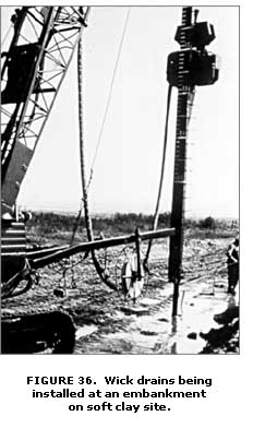
less disruptive. The most popular alternative was called a "wick drain"
and consisted of a prefabricated plastic band that had a geosynthetic filter
fabric wrapped around a central plastic core that the water moved through after
it was filtered through the wrapping (figure 36). Although these wick drains
had many significant advantages over sand drains, there were many unanswered
questions regarding design assumptions, laboratory screening tests, quality
control, installation methods, durability, and generic acceptance specifications.
Because of these disadvantages, engineers searched for a better way to create
these artificial drainage paths that would be cheaper, faster, and environmentally
less disruptive. The most popular alternative was called a "wick drain"
and consisted of a prefabricated plastic band that had a geosynthetic filter
fabric wrapped around a central plastic core that the water moved through after
it was filtered through the wrapping (figure 36). Although these wick drains
had many significant advantages over sand drains, there were many unanswered
questions regarding design assumptions, laboratory screening tests, quality
control, installation methods, durability, and generic acceptance specifications.
Recognizing the huge potential of prefabricated vertical
drains, industry responded with the development of a large number of different and mostly
proprietary models; some good, others not so good. Engineers soon discovered the need for
generic testing protocols to help them select and approve satisfactory drains.
A comprehensive FHWA research study was initiated to develop generic testing procedures
and sample specifications, as well as complete descriptions and helpful guidance for
design and construction. The study also included a parallel investigation of
prefabricated drainage sheets and boards that were becoming popular for use behind
retaining walls.
For more detailed descriptions of types and physical characteristics of these
drainage materials, the best source is FHWA-RD-86-169 for wick drains, and
FHWA-RD-86-171 for sheet drains (46,47). These reports also provide a
discussion of design considerations, recommended design procedures, guideline
specifications, and advice on construction installation, control, and
performance evaluation.
3.7 Publications and Implementation Items
Research and development activities for ground improvement techniques were very successful. Numerous quality reports and manuals were generated from this project, which is by far the most comprehensive research investigation of this topic by any single organization in the world. Numerous technology transfer items were disseminated to accelerate the implementation of this new information to highway practitioners. Many changes were made to the AASHTO Specifications (see chapter 7) and several FHWA training courses and technical circulars were developed on the basis of the research results.

