U.S. Department of Transportation
Federal Highway Administration
1200 New Jersey Avenue, SE
Washington, DC 20590
202-366-4000
Federal Highway Administration Research and Technology
Coordinating, Developing, and Delivering Highway Transportation Innovations
 |
| This report is an archived publication and may contain dated technical, contact, and link information |
|
Publication Number:
FHWA-RD-98-139
|
No less important than the categories of foundations, ground improvement, and soil behavior, a group
of studies were conducted on individual topics that didn't fit under the three major projects of the geotechnology research program.
For lack of an appropriate category title, these topics are herein referred to as stand-alone studies.
Rock mechanics and rock slope engineering were at one time considered for project status, but budget and staffing constraints reduced
the amount of effort that could be expended in this area. This is not to take away from the importance of the research that was done,
or the topics that didn't get initiated, but merely goes to show that there were a number of important issues to be addressed that
didn't have an official home or umbrella to be placed under. It was decided to include rock fall and shale research under Task 5
of the Soil Behavior project and rename the project "Soil and Rock Behavior."
5.1 Background
Two good examples of stand-alone studies are the computer-aided design system for geotechnical
engineering and the National Geotechnical Experimentation Sites program, which transcend all the boundaries of geotechnical
engineering research and practice. As discussed in chapter one, these two current assets were missing during most of the program,
and can be directly blamed for the slow advancement and difficulties that were faced in attempting to improve the state of the art
in geotechnology. Now that these assets are firmly in place, advancements should come faster and easier.
The remaining topics also helped stretch the upper bounds of the present technology limits in their own right. Some of them
contributed to more than one area of geotechnology, and a couple of them touched all the bases, not to the same extent as the
NGES or the geotechnical databases, but important nonetheless.
5.2 Automated Geotechnical Information and Design System
FHWA recently initiated a major effort to develop an Automated Geotechnical Information and Design System (AGIDS) to integrate all of the FHWA research quality technical data bases, plus the information data bases in geotechnology into a comprehensive design aid system. AGIDS (figure 43) will allow geotechnical and structural engineers to quickly and economically obtain information and evaluate design alternatives from a centralized computer source of databases. These databases will be connected by developing commonality features and the design of a user interface application for performing cross queries, correlations, and engineering analyses.
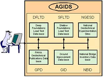
FIGURE 43. Automated Geotechnical Information and Design System.
Several of the data bases already contain modules for performing correlations, predictions,
and analyses; however, they need to be linked through a multi-user workstation that contains an interactive system for
automatically generating design solutions based on interactive user input. Such a system will take most of the guesswork
out of geotechnical design, and replace it with an objective, quantitative system that supports sound management decisions.
A wealth of research-quality geotechnical data have been gathered from the literature, SHA files, other agencies, and
foreign organizations for placement in a series of FHWA geotechnical data bases to increase the effectiveness of
current and future research efforts to improve design and prediction methods. These tools are also an effective
way for practitioners to improve their state of the practice on routine design work.
Each data base can be utilized as a stand-alone information source with its own information management and analysis
modules, plus user interface applications. Each has a statistically meaningful source of high-quality data that
can be used for the development and verification of new or improved analysis methods or simple design checks by
providing a fast, convenient, and economical source of project specific or generic information for inclusion in
reports in minutes instead of days or weeks. The data base also allows users to:
Regardless of the project stage, the needed information can be obtained rapidly, reducing time and costs to formulate plans and evaluate design alternatives, which in turn will lead to reduced uncertainty in the project development phases. A more confident design process will reduce overall geotechnical and foundation costs. A detailed description of each of the data bases follows this section.
5.2.1 Deep Foundations Load Test Data Base -
This data base provides a centrally located source of technical information on piles and drilled shafts,
including soil data, load test results, instrumentation data, and driving records that can be used to
verify and refine deep foundation theories. It can also be used to develop new theories or assist
practitioners to perform routine design projects. In addition to basic search and retrieval functions,
a correlations module and several static analysis programs have been incorporated into the data base to
facilitate the performance of a comparative analysis.
Test data and well-defined soils information from thousands of pile and drilled shaft load tests have been
collected and evaluated for inclusion in the data base. New data were also generated by making funds available
for installing instrumentation and conducting load tests on active bridge construction projects at appropriate
sites. The data base serves as a "standard" against which new and existing design procedures can be
compared. Statistical correlations can be developed from the data base and used to develop new design aids
(charts, curves, and tables) for pile and drilled shaft design procedures. The data base has been distributed
for beta testing.
The data base was developed using SYBASE System 10 tools and resides on a UNIX platform on a RISC 6000 Geotech
Server at FHWA's TFHRC. The data base operates in a Windows environment, and utilizes Menu bars, drop down lists,
icons, and message boxes to make it more user-friendly. It also allows the user to directly print results to a
local printer or be downloaded through a file transfer protocol and stored.
By entering the available choices in the menu, the user can obtain information on soils, piles, drilled shafts,
instrumentation setup, construction method, driving records, and load test data. The user can also perform design
predictions, analysis, and correlations, and obtain frequency distributions on the data available. From the
statistics menu, the user can obtain data and statistical graphs from a selection of relationships, such as the
number and types of deep foundations in a selected State, country, or in the entire data base. Statistical data
can also be obtained for load tests, soil tests, and construction methods.
5.2.2 Shallow Foundations Data Base -
The Shallow Foundations Data Base (SHALDB) is divided into two main parts: the user interface and the data base
files. The user interface is a program that enables the user to easily add, access, and modify the data files
that describe the many case histories stored in the data base. The data base files are grouped into five
categories: general information, footing data, footing behavior, soil data, and settlement predictions.
The user-friendly program was written in Visual Basic and runs under Windows 3.1. The program is in three
parts: maintenance, inquiry, and analysis. With the inquiry option, the user can select and view the footings
from the data base that satisfy a set of criteria chosen by the user. The analysis option consists of making
plots of one variable against another, such as predicted vs. measured behavior; or it can predict the settlement
of footings on sand according to 13 different methods. There are more than 150 spread footing case histories in
the data base for which either a load test was performed or the behavior was observed during and after construction.
The data base will also provide a standard format for the reporting of new tests.
The SHALDB is a valuable tool that allows the user to observe the performance of actual case histories for spread
footings of various sizes on sands with varying parameters under different loading conditions. This organized
data base can be used to evaluate existing prediction methods or to develop and/or check a new method. It will
also be useful to point out what kind of test information is missing from the data, and therefore what kind of
tests need to be performed to fill the gaps. It will be useful to practitioners as well as other researchers (28).
5.2.3 Ground Improvement Data Base -
FHWA recently joined forces with the International Center for Ground Improvement Technology in Brooklyn, New York,
to develop an International Knowledge Data Base for Ground Improvement Technology (IKDGIT). The comprehensive,
user-friendly data base provides access to experiences from many parts of the world specific to a selected
technology, application, or location. It allows the user to retrieve information on possible technologies for a
project under design by viewing similar case histories, problems encountered, possible remedial action schemes,
comparative cost data, specifications and codes, and QA/QC. The engineer is able to supplement local experience
with that of others with similar projects.
As discussed in chapter 3, ground improvement technologies have recently played a very important role in solving
major geotechnical problems in highway construction and in other civil engineering fields as well. While recent
research and development efforts have increased our knowledge base, many of the concepts have not been made fully
accessible to many in the professional world. This requires a reliable, efficient, and interactive technology
transfer process and geographical expansion of locally based experiences. The IKDGIT is a good tool that can be
used to help expedite the technology transfer process.
The data base was formed in three parts. Part One is a compendium of national and international codes of practice.
Part Two is a collection of monitored case histories that includes site observations, design methods, construction
details, and performance monitoring data. Part Three contains information on instrumented structures plus data and
analysis records on models and full-scale experimental studies.
The data base currently contains more than 200 documented records of ground improvement case histories from 15
countries. As with other technical data bases in the FHWA suite, the work is never finished. There is much more
input expected from the participating countries in the near future that will increase the value of IKDGIT in its
role as part of AGIDS.
5.2.4 Supplemental Data Bases - In addition to the three main data bases previously discussed, AGIDS will have access to the NGES and FHWA publications data bases to provide necessary technical and administrative information to assist engineers in planning, design, and construction of highway projects. The NGES data base is described in section 5.3 of this chapter. The FHWA publications data base is not described in this report; however, most of the references contained in that data base are listed in this report.
5.3 National Geotechnical Experimentation Sites (NGES)
A major focus of the FHWA geotechnology research program was the development
of a designated system of national geotechnical experimentation sites to improve our ability to find and
evaluate new techniques for constructing safer and more economical highways and bridges. With this objective
in mind, FHWA teamed up with the National Science Foundation to establish such a system with a national
management board and individual site managers. This section of the report describes the system that was
developed to help investigators accelerate geotechnical research to solve many serious geotechnical engineering
problems facing the highway community.
During the last two decades the geotechnical profession has witnessed major changes in the approach to site
characterization and quantification of soil behavior. New in-situ testing methods and improved field
instrumentation have provided valuable new tools to complement and/or create testing alternatives to laboratory
procedures. These new techniques are leading to a better understanding of the static and dynamic properties of
soils.
Although the evolution of new techniques has been relatively rapid, duplication of effort and lack of cooperative
work among the various research groups has made progress slower and more costly than might otherwise have been possible.
A lack of well-characterized, well-documented, reference sites has impeded the development and evaluation of new in-situ
testing methods.
Such sites would allow ready comparison of new methods against known soil conditions and past testing programs. In the
past, most researchers had to spend a considerable portion of their budget on creating a well-characterized site at which
to conduct their studies. Unfortunately, in many cases, these previously studied sites are no longer available or are
unknown to other researchers. As a result, the originators of a new method must perform their own extensive site investigation
before reaching the initial objectives of the research. This increases the total project cost and wastes valuable time and
effort.
Benefits from well-characterized and well-documented sites are not solely restricted to evaluation of new in-situ testing methods.
A prime objective of geotechnical engineering is to predict the performance of constructed facilities--with or without soil
and site improvement. The geotechnical profession needs to be able to evaluate its predictive capabilities by making comparisons
with records of actual field performance. Thus, new geotechnical design and construction methods may be developed and tested at
these sites, addressing not only the more conventional earthwork and design problems, but also environmental problems such as hazardous
waste containment.
To quantify ground response and ground failure potential, geotechnical earthquake engineers badly needed sites that were
well-characterized and permanently instrumented to record earthquakes. The development and verification of new tools to
assess site-specific liquefaction potential, for example, require access to cohesionless soil sites where liquefaction has
been observed during earthquakes and where soil characteristics are well-documented. Instrumentation of such sites could
provide field records for the solution of several important problems, including the quantification of pore pressure response
and deformations that develop during liquefaction. Analogous sites in clay deposits are also necessary to improve our understanding
of how such deposits amplify detrimental earthquake motions.
A workshop was sponsored by NSF and FHWA at Orlando, Florida, in October 1991 to initiate the implementation of the NGES. Participants
selected a small number of sites from a list of 40 candidate sites to form the core of the national system. The group selected the original
40 sites because they had reasonably good documentation of the soil conditions and previous experimentation results, a reasonable probability
of continued access for at least 10 years, and a soil type of sufficient interest to geotechnical researchers. An initial screening prior to
the workshop identified the nine most promising candidates for the designation of "national geotechnical experimentation site."
The evaluators decided that none of the sites met all of the criteria for selection and recommended establishing a national system of multiple
sites according to a hierarchy of graded levels that could fluctuate as conditions changed. Texas A&M University and Treasure Island, California,
the two sites that came closest to meeting all of the selection criteria, were named as Level I sites. Three sites--located at the University of
Houston, Northwestern University, and the University of Massachusetts--were found to have some limitation that dropped them into Level II. The
remaining four finalists were designated as Level III sites, and all others were grouped in Level IV. Each site will be reviewed periodically to
determine if conditions warrant upgrading to a higher level. Loss of access or other negative circumstances may also result in downgrading a
site.
The Orlando workshop participants also founded a System Management Board to set policies for the use and operation of the
sites and to ensure continuity. They also established positions for a system director and for individual site managers at
each of the top five sites--Levels I and II--that form the central core of the system. A draft plan and suggested
budget for managing the system and funding improvements to the core sites were prepared for submission to FHWA and NSF. In
1997, it was decided to add a fourth Level II site to the NGES system. The site is located near Opelika, Alabama, on property
owned by Auburn University. It has been officially designated as the Spring Villa NGES test facility.
Following the workshop, FHWA awarded a contract to develop a computerized central repository for all the data contained
in the NGES catalog, plus any future data generated at the individual test sites. The cost of this project was shared
by nine state departments of transportation--Iowa, Louisiana, Massachusetts, Minnesota, Nebraska, New York, Texas,
Washington, and Wisconsin (62).
FHWA and NSF later awarded a large system-support contract in 1992 to provide for the overall management of the program
and to operate and maintain a Central Data Repository (CDR). They awarded subcontracts to each of the five site managers
and a part-time system director. The board approved improvements to each site on the basis of proposals submitted by the
site managers.
The data base of the CDR includes graphs of representative profiles and typical plots of data for each site. Modem hookups
provide remote access to allow users to review the quality and numerical details of the results. An electronic bulletin
board provides late-breaking news about various sites and programs available within the system. The CDR is a user-friendly
system shell with online computer search and data retrieval capabilities that enable geotechnical researchers to select the
most appropriate site for their work. It can accommodate all essential information about each site, such as generalized soil
conditions, listing of all available test data, site logistics and limitations, published references, and other site
information (63).
The availability of a national system of geotechnical test sites that are already well-characterized and permanently
instrumented will serve to accelerate innovative research on soil behavior and foundation engineering. Future research
performed at these sites will be less individually oriented, with greater documentation maintained for the benefit of
other investigators.
Researchers and practitioners can exchange information and ideas through the NGES system to focus their thought
processes into more definable channels because they will be comparing theories and testing procedures against the
same reality. This, in turn, should lead to better communication of the effects of geotechnical phenomena to the
geotechnical community, thereby reducing the misunderstandings, inconsistencies, empiricism, and untested theories
that pervade geotechnical practice today.
The NGES program will foster more cooperation between public agencies, universities, and private sector groups--
something that has been missing from geotechnical engineering. In addition to providing a standardized base upon
which to judge the results of new research, NGES will provide research sponsors like FHWA, NSF, and SHA's with more
accountability than in the past, because investigators will know that others can come to the same site and repeat the
experiment.
In summary, the development of well-characterized sites that are readily available to geotechnical engineering will
encourage a variety of experimental activities, which will lead to techniques for constructing safer and more economical
structures. As an additional benefit, these improvements will make U.S. geotechnical design and construction firms more
competitive in the international arena. More information can be obtained from the references and/or the NGES web site
at "http://www.unh.edu/nges."
5.4 Evaluation and Improvement of Bridge Foundations
Various bridge components wear out or deteriorate faster than others. The deck,
in general, deteriorates faster than the superstructure and the latter in turn deteriorates faster than the
substructure, which includes the piers, abutments, and foundations. It is therefore not surprising that, in
the majority of bridge rehabilitation jobs, the substructure usually can be salvaged with relatively minor or
cosmetic repairs. Since the cost of the substructure represents a substantial portion of the overall cost of
the bridge, evaluation of the condition of the existing substructure must be considered in any bridge rehabilitation
or replacement project.
In certain instances, such as when a major change in the alignment is required to upgrade the existing structure or
hydraulic requirements dictate the removal or relocation of the substructure components within the waterway, replacement
of the substructure may be necessary. However, for widening, upgrading for increase in live loading, or replacement
with a different type deck and/or superstructure, a thorough evaluation of the substructure (including the foundations)
will be required. Correcting a deficiency to restore the integrity of an existing substructure or foundation may be
many times more difficult and expensive than correcting a deficiency either in the deck or in the superstructure.
Maintenance costs for a restored substructure may be higher than corresponding costs for a new substructure on a
bridge replacement project.
5.4.1 FHWA Research Study -
Because of potential savings, more than just cursory effort should be made to determine the feasibility of reusing
existing substructures and foundations. At the beginning of the major emphasis period for the national bridge
replacement program, it was discovered that rational guidelines for evaluating existing foundations did not
exist, nor were there useful guides on how to make improvements to restore marginally acceptable foundations
to an acceptable level of performance. In recognition of this need, FHWA initiated a contract research study
to develop the engineering guidelines for making these evaluations, and to provide guidance for improving the
soundness and bearing capacity of those units that needed upgrading to meet current standards.
It was first determined that there are many evaluation techniques and repair or construction methods that are
applicable for the deck and the superstructure of existing bridges. The same thing, however, could not be
said for the substructure, especially for those elements below the waterline or the ground line. The
decision process for the repair or replacement of a bridge can be quite subjective. The purpose of
the study, therefore, was to develop recommended guidelines for: (1) techniques for evaluating, and
(2) design guides and construction methods for improving existing bridge substructures for replacement
or rehabilitated bridges.
Part I of the guidelines report deals with deterioration of bridge substructures, effects of loading and
unloading on the foundations, time effects on soil properties, and bearing capacity and settlement of
foundations. Part II deals with current methods of inspection, substructure analysis, new methods for
evaluating soundness and bearing capacity of foundations, and instrumenting foundations for future
performance. Repair methods and techniques to increase the capacity of existing foundations by
strengthening the foundation and/or soil and methods for reducing loads on the substructure are
covered in Part III. Case histories of bridge substructures and recommendations for research in
the subject area comprise Part IV of the report (64).
Valuable contributions were made by numerous materials experts in the concrete, steel, and timber
industries pertaining to reuse and repair of bridge substructure elements. Many bridge and staff
engineers from the departments of transportation of California, Illinois, Massachusetts, New York,
Pennsylvania, and Virginia also contributed valuable information on current practices in this topic
area in their respective States that will help designers evaluate existing foundations for upgrade
studies.
5.4.2 Unknown Bridge Foundations -
During the 1980's numerous bridge collapses occurred due to scour failures of the foundation
systems, causing significant injuries, loss of life, and property damage. These events
prompted the U.S. Congress to revise the National Bridge Inspection Standards to include
an item (#113) on Scour Critical Bridges, which requires that all bridges be evaluated
for their vulnerability to scour damage. The FHWA Technical Advisory on
"Evaluating Scour at Bridges," October 21, 1991, is the implementing
document. FHWA Hydraulic Engineering Circular #18 recommends a process to
perform the scour evaluations to determine the vulnerability of existing bridges
to scour-induced collapse.
The process described in HEC-18 requires that specific knowledge of foundation
type, size, and depth be available to make the evaluations. SHA's have plans
and records on their bridge foundations for most bridges on the Federal-aid
system, except some of the older bridges and many of the off-system bridges.
A survey was completed in 1990 that included a preliminary assessment of all
bridges in categories of low scour risk, scour susceptible, or with unknown
foundations. It was recommended that a strategy be developed to help manage
the risk of not knowing the type, size, depth, configuration, or condition of
a bridge foundation. It was also necessary to develop procedures for SHA's
to use in ascertaining these unknown characteristics.
In 1991, FHWA contracted to develop the required strategy and procedures. The
study began by developing a statistical profile from the FHWA and SHA data bases
to define the extent and severity of the problem. Next, a risk-based strategy
was developed to assess and manage the risk of not knowing the foundation particulars
and help SHA's determine which bridges most urgently need these data for scour
evaluations. Finally, a method guide is presented in the final report that describes
measures that can be used to determine foundation characteristics such as type, size,
depth, and service condition.
The guidelines cover deterioration of bridge substructures, effects of loading and
unloading on the foundations, time-effects on soil properties, current methods of inspection,
and substructure analysis. Repair methods and techniques to increase the capacity of existing
foundations by strengthening the foundation and/or soil, methods for reducing loads on the
substructure, new methods for evaluating soundness and bearing capacity of foundations, and
instrumenting foundations for future performance are also covered in the report (65).
5.5 Geotechnical Risk and Reliability
Most engineers design under the condition of uncertainty with
regard to material properties, service requirements, and engineering models to name just a few.
Geotechnical engineers have a very pronounced problem with uncertainty because of the highly
variable nature of soil and rock properties. In the past, geotechnical engineers have dealt
with the high level of uncertainty by conservatively assigning or specifying much larger
capacities than the projected demand. This ratio of capacity to predicted demand is the
classical safety factor approach, which requires significant experience levels to be done right.
Risk-based design can be used to reduce some of the conservatism inherent in the factor of safety
approach by attempting to quantify these uncertainties and deal with them in a more rational manner.
Uncertainties in the data need to be identified and then quantified with statistical methods that are
easy to use. Mathematical modeling techniques can be used to estimate the effect of these quantified
uncertainties on performance predictions. This will result in a quantified measure of confidence that
the engineered structure will perform adequately.
A reliability index can be calculated to give a measure of the relative error contained in a prediction
of performance behavior with respect to the margin of safety desired in a particular structure. Although
geotechnical engineers routinely design for a "probability of failure," it is much more prudent to
use the term "reliability index" or "geotechnical reliability assessment," especially in
a court of law where an aggressive attorney would have a career day in front of a lay jury.
To assist highway engineers to make better geotechnical predictions of performance, FHWA contracted to
evaluate the state of the art and develop a Geotechnical Risk Analysis User's Guide. A report was prepared
that surveys the available literature at that time and presents a large bibliography of references to explain
the information contained in the guidelines manual. The manual shows how to quantify uncertainties and adjust
design conservatism accordingly in a simple-to-use approach. Design problems from engineering practice are
presented to illustrate the approach (66,67).
5.6 In-Situ Soil Testing
In-situ soil testing is an important method for determining geotechnical design parameters, especially for hard-to-sample soils needed for laboratory testing. Most of the current techniques in use were developed in the United States and Europe without FHWA funding; however, a few guidelines type manuals were developed by FHWA as user-friendly informational documents for U.S. highway engineer practitioners (68,69,70). In some other separate instances, FHWA spent considerable resources developing special in-situ tools to obtain soil design parameters. These efforts are described in the following sections.
5.6.1 Stepped Bladed Vane - Lateral soil pressure is an important element in soil mechanics theory and practice, but it is very sensitive to disturbance and difficult to measure. A step-tapered blade was developed to compensate for disturbance by measuring soil and pore-water pressures on three thicknesses of blades, and extrapolating for the hypothetical soil pressure at zero blade thickness. The three-bladed vane (figure 44) contains nine teflon-diaphragm pneumatic stress cells to measure soil pressure. The equipment has been shown to provide reproducible, reliable, and economic measurements of lateral stress in sands, silts, and clays.
FIGURE 44. Close-up view of step bladed vane.
The device measures quickly, accurately, and inexpensively the total and effective lateral stress in soils, which is a property that is fundamental to virtually all soil mechanics, including foundation-bearing capacity, pressure on retaining walls, and slope stability. The device and test procedures were used in a number of case histories where the design predictions were compared with measured performance. A detailed description of the equipment and sample design problems can be found in the final report (71).
5.6.2 Simplified Torsional Cylindrical Impulse Shear Test -
This device was developed in 1994 for FHWA to predict the behavior of soil deposits during earthquakes. It
provides detailed information for soil deposits on in-situ nonlinear shear stress vs. strain characteristics that
is needed for commonly used computer analysis procedures for earthquake engineering. Predictions can be made for
large ground motions and soil liquefaction that may occur during future earthquakes to prevent the source of immense losses
such as those of past earthquakes.
The impulse shear test device addresses the major problem of obtaining the required information without disturbing in-situ
conditions excessively. Disturbances can create considerable uncertainty in behavior predictions, which can lead to costly
over-design or worse unconservative designs that fail in seismically active areas. Improving our ability to estimate the soil
characteristics of interest will allow us to realize more fully the potential of dynamic geotechnical computer analysis
procedures used, for example, by the California Department of Transportation. This will lead to more effective earthquake
engineering and, in turn, to greater safety, economy, and reliability in the earthquake- resistant design of highway structures.
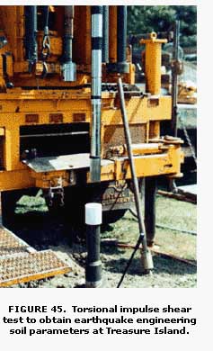 The device consists of a single cylinder with a diameter of 7 cm located at
the end of a probe that penetrates the soil below the base of a borehole. An
impulsive torque is applied to the cylinder by an excitation system to induce
shear stresses and strains in the surrounding soil. The applied torque and resulting
rotation are measured by sensors mounted in an instrumented head attached to
the top of the cylinder. Figure 45 shows the device being lowered into a soil
borehole at a seismic site on the Treasure Island NGES.
The device consists of a single cylinder with a diameter of 7 cm located at
the end of a probe that penetrates the soil below the base of a borehole. An
impulsive torque is applied to the cylinder by an excitation system to induce
shear stresses and strains in the surrounding soil. The applied torque and resulting
rotation are measured by sensors mounted in an instrumented head attached to
the top of the cylinder. Figure 45 shows the device being lowered into a soil
borehole at a seismic site on the Treasure Island NGES.
The device has been tested at several NGES facilities and at TFHRC to establish the operability of the testing system and to develop test procedures. It was found to be a promising technique from a technical and practical standpoint. Current efforts are attempting to improve the existing prototype with respect to efficiency, usability, economy, and reliability.
5.6.3 Controlled Source Spectral Analysis of Surface Waves (CSSASW) -
In addition to the two previous methods, which involve the insertion of a probe into the underlying soil, FHWA also
funded a study to investigate the use of CSSASW techniques for nonintrusive shear wave velocity profiling of soils with
high liquefaction potential. The results were compared with the results of direct measurements made at a test site with
extensive subsurface data and seismic instrumentation. FHWA has also evaluated this technique for determining the
thickness or depth of unknown bridge abutments and foundation systems.
The CSSASW system is a rapid and cost-effective technique that can accurately determine the apparent dispersion of
Rayleigh surface waves at a site, which can be correlated with shear velocity profiles to produce essential data
to analyze site response during earthquake loading. This is especially important in hard-to-sample soils. The device
(Figure 46) uses a powerful electromagnetic vibration source powered by a generator and two data receivers that pick
up the soil vibrations generated by the exciter. The Rayleigh waves are measured by the two vertically oriented
accelerometers positioned at a known distance from the exciter.
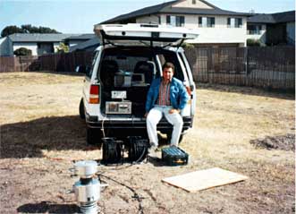
FIGURE 46. Controlled source spectral analysis of
surface waves (CSSASW) testing at Treasure Island.
5.6.4 Multiple Deployment Model Pile -
The installation of full-scale test piles to obtain pile design parameters during the design phase is sometimes used on
large projects to save money on construction costs by reducing the conservatism that generally occurs due to unknown or
unsure conditions. Conservatism leads to higher safety factors, which means higher costs. Full-scale test piles are an
expensive and inconvenient way to obtain the desired information. Geotechnical engineers have long searched for an accurate
model pile test that can properly simulate the field behavior of full-scale piles.
Many model piles have been developed during this quest. Examples include the In-Situ Model Pile (IMP) developed at Oxford
University, the MIT Piezo Lateral Stress Cell (PLSC), the Norwegian Geotechnical Institute (NGI) model pile, and many others
that are available, but none of which are quite up to par for highway bridge standards. These model piles are calibrated
tools that are equipped with instrumentation to monitor the pile-soil interaction during pile driving, soil setup with time,
and subsequent loading to failure. This behavior is measured by strain gauges, load cells, and pore pressure transducers
attached to the model pile. Some also have accelerometers and displacement transducers.
FHWA recently sponsored the development of the Multiple Development Model Pile (MDMP) for use as an in-situ soil testing
device for site investigations to obtain essential pile design parameters. The main purpose of the MDMP is to duplicate
the driving and after driving conditions that full-scale piles experience. The instrumentation must therefore be rugged
enough to withstand driving stresses and maintain the required standard of accuracy. Restrike of the model piles in clay
soils can be used to assess load transfer during pore pressure dissipation with time; thus, the pile's capacity gain from
"setup or freeze" can be accurately quantified.
The MDMP was successfully used at two sites in Newbury, Massachusetts, on a SHA bridge construction project. The results
compared very well with full-scale data from instrumented pile load tests to failure. The model results show that the
MDMP is capable of providing very accurate soil-structure interaction relations during static load testing. These
findings were used to predict the time-dependent behavior of the full-scale instrumented piles, and to reevaluate the
pile capacity gain phenomenon. These results helped to explain some unanswered questions and facilitated the development
of new procedures that incorporate pile capacity gain in design and construction.
5.7 Seismic Design of Highway Bridge Foundations
In a recent letter from Mr. James Roberts, Chief Engineer of Caltrans, to the FHWA, special emphasis was made on the need for additional research on the seismic behavior of foundation soils during major earthquakes. An excerpt from this letter follows:
"It has often been said that the October, 1989 Loma Prieta earthquake in California was the Geotechnical Engineer's earthquake because of the major impact the deep soft soils had on the bridge and roadway damage. This was the United States warning to pay more attention to the importance of soil-structure interaction and the disastrous effects of not properly designing structures constructed over these types of foundation materials. We had a warning from the damage patterns in the 1985 Mexico City earthquake and the geotechnical engineers began to alert the structural engineering community about the importance of geotechnical input to structure design. The recent Kobe earthquake reinforced the importance of foundation response to the seismic performance of structures."
The loss of life and extensive property damage suffered during recent earthquakes in California (Figure 47) and some foreign countries have emphasized the need for research to provide improved procedures and specifications for constructing highways and bridges with better earthquake resistance. FHWA increased its Seismic Research Program to evaluate the seismic vulnerability of bridges, tunnels, retaining structures, slopes, and embankments shortly after the Loma Prieta and Northridge earthquakes in the early 1990's. Much of this research is being conducted by the National Center for Earthquake Engineering Research (NCEER) in cooperation with other agencies participating in the Federally-sponsored National Earthquake Hazards Reduction Program.
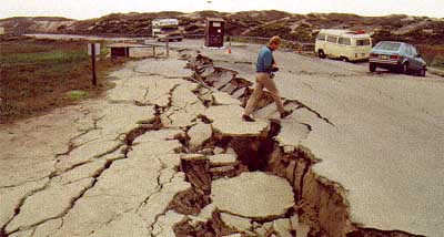
FIGURE 47. Liquefaction damage due to Loma Prieta earthquake.
NCEER is presently conducting two separate FHWA-sponsored contracts. One contract is focused on the seismic vulnerability of new highway construction, and the other is concerned with the seismic vulnerability analysis and retrofitting of existing highway structures. Revised seismic design and construction guidelines will be developed through a synthesis of existing knowledge and the development of new information from analytical and experimental research activities being conducted under the NCEER and other FHWA projects.

