U.S. Department of Transportation
Federal Highway Administration
1200 New Jersey Avenue, SE
Washington, DC 20590
202-366-4000
Federal Highway Administration Research and Technology
Coordinating, Developing, and Delivering Highway Transportation Innovations
 |
| This report is an archived publication and may contain dated technical, contact, and link information |
|
Publication Number:
FHWA-RD-98-139
|
Previous | Table of Contents | Next
The Geotechnical Laboratory at the TFHRC includes soil
mechanics, soil behavior, and foundations testing facilities. The primary functions
of the laboratory are to determine mechanical properties of ground materials and to
evaluate soil-structure interaction for bridge foundations and retaining walls. In
addition, the laboratory can perform rock mechanics, geophysical, and in-situ testing
of various ground materials.
The GT laboratory facilities are capable of conducting all of the standard tests for
characterizing ground materials. In addition, model tests of piles, drilled shafts,
spread footings, and reinforced soil retaining systems can be conducted in large
laboratory tanks and test pits. Automatic pile drivers, an overhead crane, and
load testing reaction frames are available to conduct evaluations of load/settlement
relationships of instrumented foundation systems.
The indoor facility houses a below grade, 2-m cubical test pit, plus several
1.5-m-diameter by 1.5-m-deep steel tanks for testing smaller scale models in
both sand and clay. Loading is provided by a 16,250-kg reaction frame and a
specially designed jacking system that allows for the precise measurement of
extremely small loads in both compression and tension (extraction tests).
An overhead, 5-ton capacity crane is available for loading and unloading
equipment and materials in the sunken pit and test tanks. A small model
automatic pile driver is also available to drive 250-mm- to 1-m-long model
piles into sand or clay test tanks or pits. The driving weights can be
varied in small increments and adjustments can be made in the number of
blows per minute.
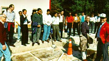
The GT outdoor facility (figure 48) consists of two, 7.0 x 5.5 x 6.0 m test
pits with concrete walls and drilled shafts anchored in bedrock for reaction
loads up to 255,000 kg. The pits are filled with sand or clay to support
either shallow or deep foundation systems for the experimental test programs.
In one corner of each pit is a sump pump that is used to control the water level.
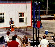
The pits are served by a test control building that houses the data acquisition
system, the load testing equipment, and a larger model pile driving rig (figure 49)
that operates much the same as a prototype pile driver by releasing heavy weights
from a certain height to free fall and develop up to 2,000 ft-lbs of driving energy
(maximum 500-lb weight falling a maximum of 4 ft (1.3 m) to top of pile).
 |
 |
|
|
FIGURE 48. Tour group at the GT outdoor facility. |
FIGURE 49. Pile driving of model piles at TFHRC. |
A recent acquisition includes a 4 MN Statnamic device with a catch mechanism, which was the first American-owned Statnamic device. The first project was a series of load tests on model groups of piles at TFHRC (figure 50). The second project was a group load test of stone columns in cooperation with the Hayward Baker Co. and the University of South Florida. The third project was a series of lateral and vertical load tests on drilled shafts at the Auburn University, NGES facility. A total of 10 axial and 4 vertical Statnamic tests were performed at Auburn. The results will be compared with static testing at the site.
The GT outdoor facility also includes a mobile pile testing tractor and trailer that was originally developed for the FHWA Demonstration Projects Division under Demonstration Project No. 66 on Pile Foundations. At the conclusion of the project, the trailer was transferred to the Geotechnical Research Unit at TFHRC. The trailer includes a large, 1,000-ton (890-MN) load frame with air compressor, generator, four 300-ton jacks, load cells, LVDT's, and instrumentation readout devices. The reaction system must be provided at the test site. The FHWA trailer comes with four high-strength (A514) plates to provide connection between the load frame and the anchorage system.
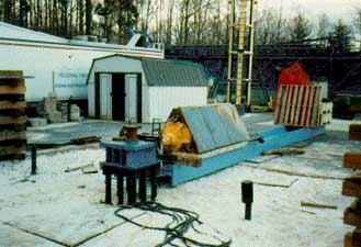
FIGURE 50. Lateral statnamic load test on
model pile group at TFHRC.
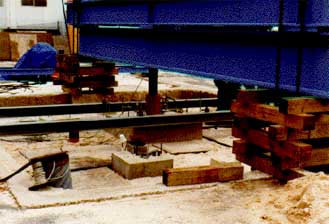
FIGURE 51. Spread footing load test.
Researchers from the GT laboratory perform comprehensive load-testing studies on deep and shallow foundation systems (figures 51 and 52) to observe performance and to obtain load settlement behavioral data for analytical studies to improve foundation design procedures. Data are stored in recently developed geotechnical data bases for future analysis by staff using a number of new computer modeling techniques. The data bases will provide a valuable standard against which new and existing design procedures can be compared.
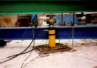
FIGURE 52. Plate load test.

