Junction Loss Experiments: Laboratory Report
APPENDIX A. VELOCITY PROFILES AT 5 MM INCREMENTS
The following images show examples of the velocity profile in the outflow pipe from one of the miniculvert experiments. Blue indicates low velocity, while the spectrum toward red reflects increasing magnitudes of local velocity.

Figure 25. Image. Example velocity profile at the outlet.

Figure 26. Image. Example velocity profile 5 mm (0.19 inch) from the outlet.
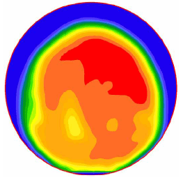
Figure 27. Image. Example velocity profile 10 mm (0.39 inch) from the outlet.
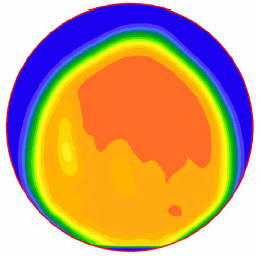
Figure 28. Image. Example velocity profile 15 mm (0.59 inch) from the outlet.
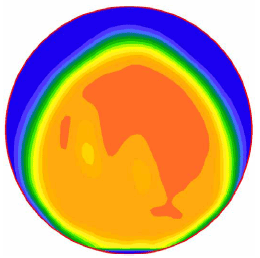
Figure 29. Image. Example velocity profile 20 mm (0.79 inch) from the outlet.
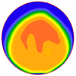
Figure 30. Image. Example velocity profile 25 mm (0.98 inch) from the outlet.
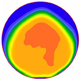
Figure 31. Image. Example velocity profile 30 mm (1.18 inches) from the outlet.
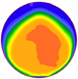
Figure 32. Image. Example velocity profile 35 mm (1.38 inches) from the outlet.

Figure 33. Image. Example velocity profile 40 mm (1.57 inches) from the outlet.
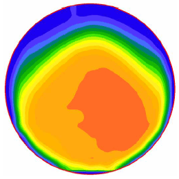
Figure 34. Image. Example velocity profile 45 mm (1.77 inches) from the outlet.
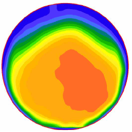
Figure 35. Image. Example velocity profile 50 mm (1.97 inches) from the outlet.
Previous | Contents | Next
| 