U.S. Department of Transportation
Federal Highway Administration
1200 New Jersey Avenue, SE
Washington, DC 20590
202-366-4000
Federal Highway Administration Research and Technology
Coordinating, Developing, and Delivering Highway Transportation Innovations
 |
| This report is an archived publication and may contain dated technical, contact, and link information |
|
Publication Number: FHWA-HRT-06-106 Date: September 2009 |
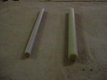
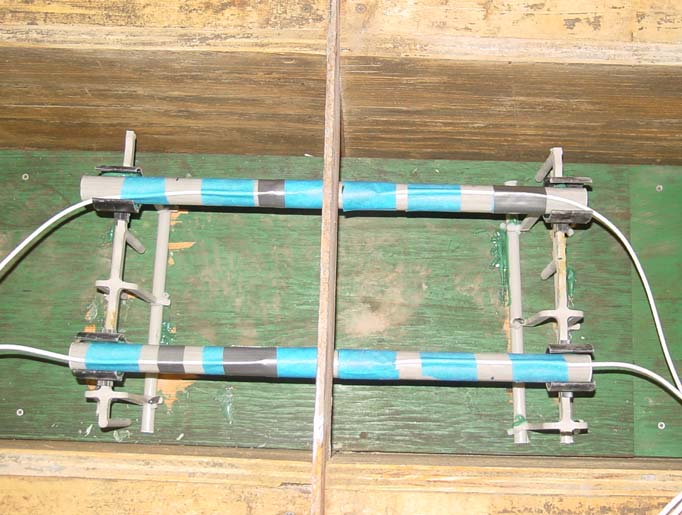
CHAPTER 3. MATERIALS, EQUIPMENT, AND LABORATORY TESTING PROCEDURESINTRODUCTIONMechanical properties of dowel bars affect the behavior and performance of JPCP provided with FRP and steel dowels. This chapter discusses mechanical properties of FRP and steel dowels and test setup in the Major Units Laboratory of WVU. Seven full-scale JPCPs (two with a dimension of 30.48 by 30.48 by 304.8 cm (12 by 12 by 120 inches) and five with a dimension of 30.48 by 27.94 by 304.8 cm (12 by 11 by 120 inches) were cast with simulated contraction or sawcut joints. The specimens were subjected to both static load and fatigue load with a frequency of about 4.0 Hz. MATERIAL PROPERTIESClass K concrete (25.856 and 31.026 MPa (3,750 and 4,500 psi) and two different diameters (3.81 and 2.54 cm (1.5 and 1.0 inch)) of GFRP dowel and epoxy-coated steel dowels were used for casting the concrete pavements in the structural laboratory. Relevant material properties are provided in this section. The two slabs that were used for preliminary testing consisted of fc ′ of 25.856 MPa (3,750 psi); the remainder of the five slabs consisted of fc ′ of 31.026 MPa (4,500 psi), as found through cylinder tests. GFRP DowelsGFRP dowels provided by independent manufacturers are pultruded with continuous E glass filaments and polyester resin. Typically, filaments are drawn through a resin bath, sized by an appropriate die, to form the dowel bar. An ultraviolet inhibitor is added to the resin to resist effects of sunlight. Dowels with 3.81- and 2.54-cm (1.5- and 1.0-inch) diameters were used in this project. Other researchers have commented on using 4.45-cm (1.75-inch)-diameter FRP dowel bars instead of 3.81-cm (1.5-inch)-diameter dowel bars. However, researchers have noted that increased bar diameter result in larger RD. Hence, it was decided to use lower diameter bars in this research.(9) Figure 3 shows two types of GFRP dowels used in this research. Table 1 and table 2 show properties of FRP bars listed by the manufacturer.
Table 1. Modulus of elasticity (MOE) test results of FRP rod specimens—ASTM D3916
1 inch = 2.54 cm Table 2. Shear test results of FRP rod specimens—single-shear fixture.
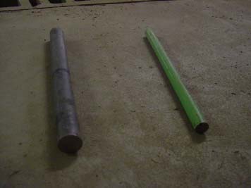
1 inch = 2.54 cm Steel DowelsThe steel dowels used in this research, shown in figure 4, were grade 40 plain uncoated steel or epoxy-coated steel. Dowels with 3.81- and 2.54-cm (1.5- and 1.0-inch) diameters were used for laboratory experiments and field installation.
ConcreteClass K ready-mixed concrete was used for laboratory slab casting. The compressive strength of the concrete was 25.856 MPa (3,750 psi) for 30.48-cm (12-inch)-thick slabs and 31.026 MPa (4,500 psi) for 27.94-cm (11-inch)-thick slabs. Concrete was poured in formwork, and forms were removed after 24 hours. The concrete beams were cured 28 days by wet burlap and plastic sheet covering. BaseTo simulate a stiff subgrade used in the field, a base layer of limestone aggregates was prepared and compacted to a depth of 40.64 cm (16 inches) in a wood-framed bin shown in figure 5. The modulus of subgrade reaction k was determined from plate loading tests in the laboratory. Based on the measured values, an average of 11.072 kg/cm3 (400 lbs/pci) was used for all tests employing aggregate base. The value was also applied to the theoretical calculations. FORMWORKFigure 5 and figure 6 show wood formworks made for casting concrete slabs in the laboratory. TEST SETUPSpecimen FabricationSeven different slabs were cast with FRP and steel dowels using different spacing and diameters.
1 inch = 2.54 cm Material PreparationsFRP and steel dowels were prepared with slots at locations where strain gauges were going to be placed. Uniaxial strain gauges were bonded to dowels at the slot position shown in figure 7. Strain gauges were protected using M-Coat-J (polysulfide liquid polymer). 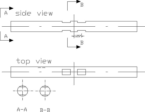
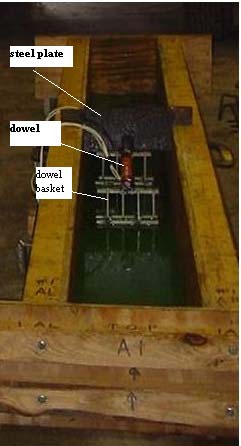
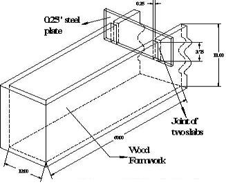
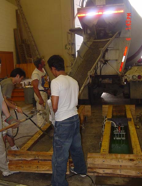
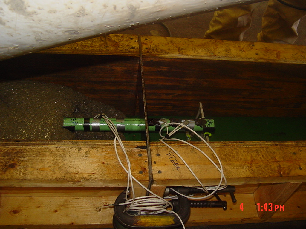
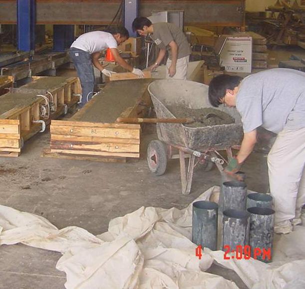
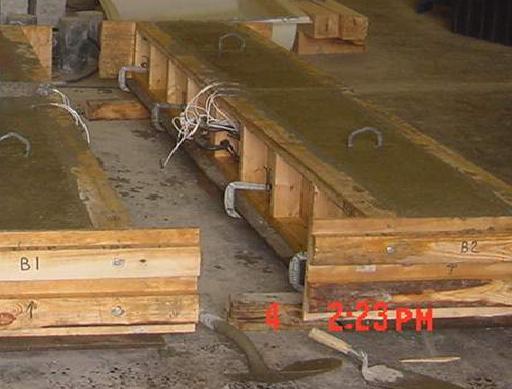
1 inch = 2.54 cm Pavement Slab CastingThe inside walls of the wood formworks were oiled so that the concrete pavement slabs could be easily demolded. Strain gauge instrumented dowels were then placed in dowel baskets to properly center them in the joint (figure 8). A steel plate with 0.635-cm (0.25-inch) thickness was placed in the middle to simulate a contraction or sawcut joint in the concrete pavement (figure 5, figure 6, and figure 8). Figure 9 through figure 12 show the slab casting. Class K concrete conforming to the West Virginia Department of Transportation (WVDOT), Department of Highway (DOH) specification was used for casting (figure 11). Concrete cylinders were cast simultaneously to obtain concrete compressive strength. Twenty-four hours after casting the beams and cylinders, curing was carried out using wet burlaps.
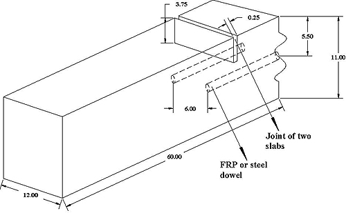
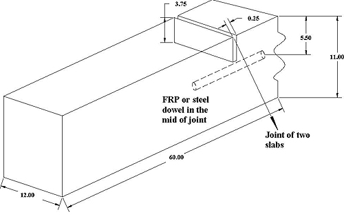
Test SpecimensTwo specimens with dimensions of 30.48 by 30.48 by 304.8 cm (12 by 12 by 120 inches) (figure 13) were cast for preliminary tests. Only FRP dowels were used as load transfer devices in these two specimens. 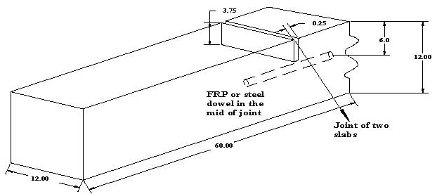
1 inch = 2.54 cm Five different concrete slabs were cast with FRP and steel dowels with different spacings and diameters (table 3). Two embeddable strain gauges were positioned vertically on both sides of a dowel across the joint to measure concrete strain at loaded side and unloaded side. Details of concrete specimens and dowels are provided in figure 14, figure 15, and table 3. Table 3. Dowel details in specimens.
c/c = Center to center
specimen is symmetrical about the joint plan (unit: inch)
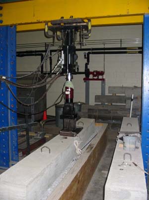
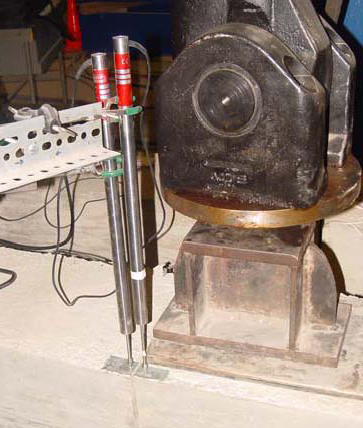
Test Setup and InstrumentationJointed concrete slabs were placed on an aggregate base inside a wooden box to simulate field conditions. The base was 15.24 cm (6 inches) high, 45.72 cm (18 inches) wide, and 304.8 cm (120 inches) in length. The modulus of subgrade reaction k was obtained from tests on this base through load application on a standard steel plate.(10) Pavement load was applied on one side of the joint (figure 16 and figure 17) using a 244.65-kN (55-kip) hydraulic actuator system through a controller. A 0.635-cm (0.25-inch)-thick steel plate 25.4 by 40.64 cm (10 by 16 inches) was connected to the actuator to simulate the load from a dual tire wheel load. An additional neoprene pad was used between the steel plate and the concrete surface to prevent any local damage during the test. Two calibrated linear variable differential transformers (LVDTs) were used to measure joint deflections at the loaded and unloaded sides of the joint. Strain gauges, LVDTs, and the load cell from the actuator were connected to a data acquisition system to automatically record data during the tests.
Static TestingLoad was applied at different increments to simulate an HS25 wheel load and/or higher load. Deflections and strains were recorded automatically by the data acquisition system. Details of the load applied on different concrete slabs are shown in table 4. Table 4. Details of static testing.
1 kip = 4.448 kN Fatigue TestingThe load from the hydraulic actuator system was set at the required range of fatigue cycles (table 5) and was applied using a sine wave. After every 1 million cycles, a static test was conducted on the pavement system to measure strain and deflections. Details of fatigue tests are provided in table 5. Table 5. Details of fatigue testing.
— No loading at corresponding cycles. It should be noted that slabs number 1 through 3 had 55.60 kN (12.5 kips), and slabs number 4 and 5 had 48.93 kN (11 kips) of loading corresponding to HS25 loading as described in chapter 6 of this report. |
|||||||||||||||||||||||||||||||||||||||||||||||||||||||||||||||||||||||||||||||||||||||||||||||||||||||||||||||||||||||||||||||||||||||||||||||||||||||||||||||||||||||||||||||||||||||||||||||||||||||||
| Page Owner: Office of Research, Development, and Technology, Office of Infrastructure, RDT Page Contact: Feedback Form Scheduled Update: Archive - No Update Technical Issues: TFHRC.WebMaster@dot.gov Topics: research, infrastructure, pavements, concrete, design, jointed, fiber-reinforced polymer, FRP, dowels Keywords: research, infrastructure, pavements, concrete, design, GFRP, glass fiber-reinforced polymer, FRP dowel, JPCP, jointed plain concrete pavement, relative deflection, joint efficiency, dowel TRT Terms: |
United States Department of Transportation - Federal Highway Administration
|