CHAPTER 6. ANALYTICAL EVALUATION
INTRODUCTION
Pavement performance (RD and LTE) in JPCP with the FRP dowel as the load transfer device depends on many design parameters such as dowel diameter, dowel spacing, joint width between adjacent slabs, pavement thickness, concrete strength, base and sub-base properties, and environmental conditions including temperature variation. In this chapter, analytical evaluation is carried out for pavement slabs with FRP dowels.
Several examples provided in this chapter illustrate computations for group action of dowels, maximum bending and shear deflection of dowels, pavement RD, and bearing stresses. Both steel and FRP dowels are used for Comparison.
The expansion joint model is used as the analytical model; the contraction joint model is also discussed and compared.
ANALYTICAL MODEL
Computations for a JPCP are carried out by assuming the dowel to be a beam and the concrete to be a Winkler foundation. Based on the original solution by Timoshenko and Lessels for the analysis of beams on an elastic foundation, the differential equation of the deflection of a beam on an elastic foundation is given as follows:(11)

(4)
In equation 4, k is the modulus of foundation, a constant, and y is the deflection. The modulus of foundation denotes the reaction due to load per unit length when the deflection is equal to unity. Timoshenko and Lessels gave a solution to the differential equation as follows (equation 5):(13)
Equation 5. y equals the sum. y equals the sum of the exponent of the product of beta times x, multiplied by that exponent with the sum of uppercase A times cosine of beta times x plus uppercase B times sine of beta times x, end of sum, adding the exponent of product of negative beta times x, multiplied by that exponent with the sum of uppercase C times cosine of beta times x plus uppercase D times sine of beta times x.
y = e (Acos βx + Bsin βx)+ e (C cos βx + Dsin βx)
(5)
Where beta is defined as the following (equation 6):

(6)
With relative stiffness of a dowel embedded in concrete, where:
k = Modulus of foundation (MPa (psi)).
E = Modulus of elasticity of the beam (MPa (psi)).
I = Moment of inertia of the beam (cm4 (inches4)).
A, B, C, and D are constants determined from the boundary conditions for a particular beam on
an elastic foundation. For a semi-infinite beam on an elastic foundation subject to a point load and moment applied at its end, as shown in figure 95, constants A and B are equal to zero and C and D are equal to the following (equation 7):

(7)
After substituting A, B, C, and D (equation 8), equation 5 becomes the following:

(8)
Loads P and M0 are positive in figure 95. By considering downward deflection as positive and the differentiating equation in equation 8 with respect to x gives slope, dy/dx, of the beam along its axis, as follows (equation 9):

(9)

Figure 95. Diagram. Semi-infinite beam on an elastic foundation.
Applying the solution for a semi-infinite beam on an elastic foundation to dowel bars, Friberg developed equations for determining the slope and deflection of a dowel at the face of a joint as shown in figure 96.(14)
Figure 96. Diagram. Slope and deflection of dowel at joint face.
Substituting –Ptz/2 for M0 (equation 10) and setting x equal to zero in equation 8, slope dy0/dx and the maximum deflection, y0, of the dowel at the face of the joint are given by equation 11 and equation 12, respectively.(14)

(10)

(11)

(12)
Where:
β = Relative stiffness of the dowel bar encased in concrete (cm-1 (inch-1)).
K0 = Modulus of dowel support (kg/cm3 (pci)).
Ed = Modulus of elasticity of the dowel bar (MPa (psi)).
Id = Moment of inertia of the dowel bar (cm4 (inch4)).
Pt = Load transferred through the dowel (metric ton (lb)).
d = Diameter of dowel bar (cm (inch)).
z = Joint width (cm (inch)).
Friberg replaced the modulus of foundation k with the expression K0d. The modulus of dowel support, K0, denotes the reaction per unit area due to applied load when the deflection is equal to unity. Thus, relative stiffness of a dowel embedded in concrete, β , is given by (equation 13):(14)

(13)
K0 is an important parameter in Friberg’s design equation. K0 is determined empirically because of the difficulty in establishing it theoretically.(14) Literature reviews indicate a wide range of values for the modulus of dowel support. Modulus of dowel support K0 increases with increased concrete strength (fc ′), decreases with increased concrete depth below the dowel, and decreases with increased dowel bar diameter. Yoder and Witczak found that K0 ranges between 300,000 and 1.5 million pci (8,303.972 and 41,519.858 kg/cm3). For analytical calculations in this chapter, a value of 1.5 million pci (41,519.858 kg/cm3) is used as suggested by Yoder and Witczak to simulate the worst scenario.(15)
Friberg’s equations were derived assuming a dowel bar of semi-infinite length.(14) Dowel bars used in practice are of finite length (typically a total length of 45.72 cm (18 inches)); therefore, this equation would not apply. However, Albertson and others have shown that this equation can still be applied to dowel bars with a β L value greater than or equal to 2 with little or no error, where the length of the dowel bar embedded in one side of the slab is denoted as L.(16)
Load Transfer Across a Joint
If 100 percent LTE is achieved by the dowel bars, about 50 percent of the wheel load would be transferred to the subgrade while the other 50 percent would be transferred through the dowels to the adjacent slab. However, repetitive loading of the joint results in the creation of a void directly above or beneath the dowel at the face of the joint. According to Yoder and Witczak, a 5–10 percent reduction in load transfer occurs upon formation of this void; therefore, a design load transfer of 45 percent of the applied wheel load is recommended (equation 14).(15)
Equation 14. Uppercase P subscript t. Uppercase P subscript t equals the product of 0.45 times uppercase P subscript w.
Pt = 0.45Pw
(14)
(Uppercase P subscript t equals the product of 0.45 times uppercase P subscript w )
Where:
Pt = Load transferred across the joint (metric ton (lb))
Pw = Applied wheel load (metric ton (lb)).
Based on Westergaard’s solutions, Friberg found that only the dowels contained within a distance of 1.8 lr from the load carried the applied load, where lr is the radius of relative stiffness, defined as the stiffness of the slab relative to the stiffness of the foundation.(17) Radius of relative stiffness (lr) is determined by the following formula (equation 15):

(15)
Where:
Ec = Modulus of elasticity of the pavement concrete (MPa (psi)).
Ec = 57,000(fc ′)05.
h = Pavement thickness (cm (inch)).
ν = Poisson’s ratio for the pavement concrete.
k = Modulus of subgrade reaction (g/cm3 (pci)).
The modulus of subgrade reaction k is a measure of the strength of the supporting soil (equation 16), which may be the sub-base or the subgrade. Its value is given in kilograms per cubic centimeter (kg/cm3) (pounds per square inch per inch (pci)) deflection as shown in 1 pci = 0.02768 kg/cm3.

(16)
A linear distribution of the load transferred across the joint is typically used, as shown in figure 97:
Pw
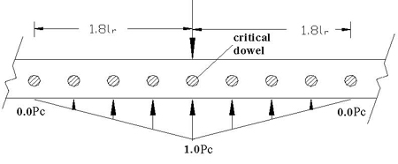
Figure 97. Diagram. Load transfer distribution proposed by Friberg.(14)
However, Tabatabaie et al. found that an effective length of 1.0 lr from the applied wheel load is more appropriate for dowels used in practice today (figure 98). A linear approximation was also shown to exist with the maximum dowel shear occurring directly beneath the load and decreasing to a value of zero at a distance 1.0 lr from the load.(18)
Pw
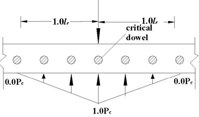
Figure 98. Diagram. Load transfer distribution proposed by Tabatabaie et al.(18)
From figure 99, the most critical case is that of the critical dowel being located at the edge of a slab.
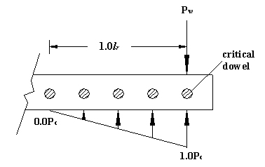
Figure 99. Diagram. Most critical dowel at the edge of a slab.
If the force transferred by a critical dowel, which is located directly beneath the wheel load, is designated as Pc, then the shear force in any other dowel within lr is determined by multiplying the height of the triangle below that particular dowel by Pc. A value of 1.0 is assumed for the height of the triangle directly below the load, as shown in figure 98. The shear force in the dowel directly under the load is obtained by piding the transferred load, Pt, by the number of effective dowels, as shown in equation 17. The sum of the heights of the triangle under each dowel within lr gives the number of effective dowels.

(17)
The bending moment (equation 18) and shear force (equation 19) along the dowel from the face of the joint can be expressed as follows:

(18)

(19)
Where:
x = Distance along dowel from face of concrete (cm (inch)).
M0= Bending moment on dowel at face of concrete (see equation 10).
Pt = Transferred load.
Ed Id = Flexural rigidity of dowel.
The RD between slabs is shown in figure 100, and the expression of  is shown in equation 20. is shown in equation 20.
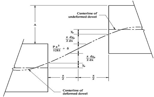
Figure 100. Diagram. RD between concrete slabs (Porter and Guinn).(19)

(20)
Where:
y0 = Dowel deflection (from equation 12).
 = Deflection due to the slope of dowel = Deflection due to the slope of dowel

(21)
Where:
 = Form factor, equal to 10/9 for solid circular section. = Form factor, equal to 10/9 for solid circular section.
A = Cross-sectional area of the dowel bar.
G = Shear modulus.
Pt = Load transferred by critical dowel.
z = Joint width.
 = Flexural deflection. = Flexural deflection.
For small joint width, deflections due to slope and flexure are very small, thus neglecting those terms in equation 20 and obtaining equation 22, as follows:

(22)
Bearing Stress Between Dowel/Concrete Interfaces
The load acting on a dowel is transferred to the supporting/embedding concrete through bearing. Assuming the dowel behaves as a beam on an elastic foundation, the bearing stress at the face of the joint  bis proportional to the deformation as shown in equation 23, as follows: bis proportional to the deformation as shown in equation 23, as follows:

(23)
The bearing stress defined by equation 23 should not exceed the allowable value. The following equation 24 was given by American Concrete Institute’s (ACI) Committee 325.(20)

(24)
Where:
fb = Allowable bearing stress (MPa (psi)).
d = Dowel diameter (cm (inch)).
fc′ = Ultimate compressive strength of concrete slab (MPa (psi)).
Joint efficiency is determined by the pavement’s ability to transfer part of an applied load across the joint to the adjacent slab. AASHTO and ACPA use deflection measurements to determine the efficiency of a joint. Equation 25 is given by ACPA as a means of rating joint effectiveness.(11)

(25)
Where:
E = Joint effectiveness (percent).
dU = Deflection of the unloaded side of a joint (cm (inch)).
dL = Deflection of the loaded side of a joint (cm (inch)).
A joint effectiveness of 75 percent or more is considered adequate for medium to heavy truck loadings. AASHTO adopts the 75 percent criteria and gives equation 26 for determining joint effectiveness associated with a 4.082-metric ton (9,000-lb) wheel load, as follows:(1)
 (26) (26)
Where:
LTE = Load transfer efficiency (percent).
AASHTO also suggests that a LTE value between 70 and 100 percent is very good load transfer; the joint provides sufficient load transfer.(1) Deflection measurements for use in equations 25 and 26 should be taken at the location of the outside wheel path.
However, LTE and E are related by equation 27:
 (27) (27)
According to equation 3, an LTE of 60 percent corresponds to an E of 75 percent. When the value of LTE is between 60 and 100 percent, the joint still provides sufficient load transfer for heavy load.
In this research, the joint LTE defined by AASHTO will be used to evaluate the performance of jointed pavements containing dowels.
Calculations have been carried out for two dowel diameters (3.81 m (1.5 inches) and 2.54 cm (1.0 inch) for both FRP and steel dowels. Other parameters considered for calculation are listed in examples 1 through 4.
Theoretical calculations for concrete pavement joints having FRP and steel dowels with 3.81-cm (1.5-inch) diameter (figure 101) are provided in examples 1 through 4.

Figure 101. Diagram. Expansion joint model used for theoretical calculation.
Example 1
Example 1 calculates the following items for concrete pavement having 3.81-cm (1.5-inch)-diameter FRP dowels:
- Radius of relative stiffness.
- Number of effective dowels.
- Load carried by the critical dowel.
- RD
 between joints. between joints.
- Bearing stress on dowel-concrete interface.
Note that parameters listed below correspond to actual laboratory setup and/or field values that provide with useful Comparisons.
FRP dowel.
Diameter, d = 3.81 cm (1.5 inches).
Length, L= 45.92 cm (18 inches).
Spacing between each dowel, b = 30.48 cm (12.0 inches).
Modulus of elasticity, Ed = 37.921 MPa (5.5 × 10⁶ psi).
Shear modulus of dowel, G = 2.8 × 10⁴ MPa (0.4 × 10⁶ psi).
Moment of inertia of the dowel (equation 28),

(28)
Cross-sectional area of dowel, A = 4.496 cm2 (1.77 inches2).
Concrete pavement.
Compressive strength, fc′ = 31.026 MPa (4,500 psi).
Modulus of elasticity (equation 29),
Ec = 57,000 × (fc′)0.5
(29)
Pavement thickness, h = 27.94 cm (11 inches).
Joint width, z = 0.635 mm (0.25 inch).
Poisson’s ratio of concrete,  = 0.2. = 0.2.
Modulus of dowel support, K0 = 41,519.858 kg/cm3 (1.5 million) pci.
Base.
Modulus of subgrade reaction, k = 11.072 kg/cm3 (400 pci).
Load.
Design traffic load HS25, applied wheel load Pw = 9.071 metric tons (20,000 lbs).
Design load transfer by joint = 45 percent.
Pt = load transferred across the joint = Pw × 0.45 = 4.082 metric tons (9,000 lbs).
Calculation steps are shown in the following flow chart with equations (figure 102).
Figure 102. Diagram. Steps for calculating critical dowel load, joint RD, and bearing stress in JPCP.
Details of the calculations are given below from step 1 to step 5.
Step 1. Calculation for radius of relative stiffness (equation 30):

(30)
Step 2. Calculation for number of effective dowels:
The dowels within 1.0 lr distance are effective in load distribution (see figure 98). Number of dowels in 1.0 lr distance (equation 31):

(31)
Where:
lr = Radius of relative stiffness.
b = Dowel spacing.
The critical dowel in this dowel group, which is the dowel directly under the load, has an effect of 1.0 (figure 98 and figure 99), and other dowel contributions were calculated according to the triangular ratio. Load was distributed on five dowels (one critical dowel plus two effective dowels on each side) by a triangular variation with due consideration to the available pavement width (see figure 103).
Figure 103. Diagram. Generalized effective dowels for load distribution.
In order to obtain the most critical load condition, it is assumed that the critical dowel is located on the edge of the pavement. Thus, the effective dowel number is reduced to three (one critical dowel and two effective dowels on one side) (see figure 104).
Figure 104. Diagram. Most critical load distribution on effective dowels.
From calculations, the number of effective dowels = 1.0 + 0.6298 + 0.2597 = 18,895.
Step 3. Calculation for load carried by the critical dowel:
When wheel load is applied at the edge of the pavement, the critical dowel has to carry most of the transferred load as shown in equation 32 (from equation 17 and figure 97):

(32)
Note, that to obtain the same critical load for lab experiments, the following is necessary at the loaded side of the pavement:
 = 4.802 metric tons (10,584.7716 lb) = 4.802 metric tons (10,584.7716 lb)
Step 4. Calculation for RD  between joints (from equation 12): between joints (from equation 12):
Maximum dowel deflection, as follows:

(33)
Where (from equation 13):

(34)
Dowel shear deflection (from equation 21), as follows:

(35)
Where:
 = Form factor, equal to 10/9 for solid circular section. = Form factor, equal to 10/9 for solid circular section.
So, total RD between pavement joints is (from equation 22) is shown in equation 36:

(36)
Step 5. Calculation for bearing stress on dowel-concrete interface:
Maximum bearing stress occurs at the place where deflection is maximum (from equation 23) as calculated in equation 37.

(37)
The allowable bearing stress is (from equation 24) as calculated in equation 38:

(38)
Thus,  b > fb (5,596.05 > 3,750); the bearing stress limit is not satisfied. b > fb (5,596.05 > 3,750); the bearing stress limit is not satisfied.
Theoretical equations derived for dowels from the expansion joint model include the shear deflection term (equation 39) due to the presence of joints with a width of 0.635 cm (0.25 inch).

(39)
However, depth of contraction and construction joint model (figure 105) (typically ¼ to ⅓ of the pavement thickness) will not reach the dowel surface because the dowel is always surrounded by concrete. To calculate these types of concrete pavement joints, the effective joint width z used for theoretical calculation will be much smaller than 0.635 cm (0.25 inch), say 0.0793 cm (0.0313 inch). This will result in less maximum bending deflection ( y0) and much smaller shear deflection (equation 21) (see table 32 for detailed calculations).
Figure 105. Diagram. Pavement contraction joint model.
Example 2
Example 2 calculates the following items for concrete pavement having 3.81-cm (1.5-inch) steel dowels:
- Radius of relative stiffness.
- Number of effective dowels.
- Load carried by the critical dowel.
- RD
 between joints. between joints.
- Bearing stress on dowel-concrete interface.
Parameters used for calculation in example 2 are similar to those in example 1, except that the dowel parameters have been changed to steel dowel properties.
Note that parameters listed below correspond to actual laboratory setup and/or field values that provide useful Comparisons.
Steel dowel.
Diameter, d = 3.81 cm (1.5 inches).
Length, L = 45.72 cm (18 inches).
Spacing between each dowel, b = 30.48 cm (12.0 inches).
Modulus of elasticity, Ed = 20.0 × 10⁴ MPa (29 × 106 psi).
Shear modulus of dowel, G = 7.58 × 10⁴ MPa (11 × 106 psi).
Moment of inertia of the dowel bar,

(40)
Cross-sectional area of dowel, A = 4.496 cm2 (1.77 inches2).
Calculation steps are the same as those for FRP dowel and are shown in figure 102.
Step 1. Calculation for radius of relative stiffness (from example 1):
lr = 82.342 cm (32.418 inches).
Step 2. Calculation for number of effective dowels (from example 1):

(41)
Step 3. Calculation for load carried by the critical dowel (from example 1) as shown in
equation 42:

(42)
Note, that to obtain the same critical load for lab experiments, the calculation shown in
equation 43 is necessary (from example 1) at the loaded side of the pavements.

(43)
Step 4. Calculation for RD  between joints is done by using equations 44 through equation 46, as follows: between joints is done by using equations 44 through equation 46, as follows:
Maximum dowel deflection,

(44)
Where:

(45)
Dowel shear deflection,

(46)
Step 5. Calculation for the bearing stress on dowel-concrete interface (from equation 23) is given by equation 47, as follows:
 (47) (47)
The allowable bearing stress is (from equation 24) calculated from equation 48, as follows:

(48)
Thus,  b < fb, 24.674 < 25.855 MPa (3,578.62 < 3,750 psi); the bearing stress limit is
satisfied. b < fb, 24.674 < 25.855 MPa (3,578.62 < 3,750 psi); the bearing stress limit is
satisfied.
Theoretical calculations for concrete pavement joints having FRP and steel dowels with 2.54-cm (1.5-inch) diameter (figure 101) are provided in examples 3 and 4. The expansion joint model (figure 101) is used for calculations. For convenience, figure 101 is shown here again, as
figure 106.
Figure 106. Diagram. Expansion joint model used for theoretical calculation.
Example 3
Example 3 calculates the following items for concrete pavement having 2.54-cm (1.0-inch) FRP dowels:
- Radius of relative stiffness.
- Number of effective dowels.
- Load carried by the critical dowel.
- RD
 between joints. between joints.
- Bearing stress on dowel-concrete interface.
Note that parameters listed below correspond to actual laboratory setup and/or field values that provide useful Comparisons:
- FRP dowel.
- Diameter, d = 2.54 cm (1.0 inch).
- Length, L = 45.72 cm (18 inches).
- Dowel spacing, b = 15.24 cm (6.0 inches).
- Modulus of elasticity, Ed = 4.14 × 10⁴ MPa (6.0 × 10⁶ psi).
- Shear modulus of dowel, G = 0.28 × 10⁴ (0.4 × 10⁶ psi).
- Moment of inertia (equation 49),

(49)
- Cross-sectional area, A = 1.995 cm2 (0.7854 inch2).
- Concrete pavement.
- Compressive strength, fc′ = 31.026 MPa (4,500 psi).
- Modulus of elasticity (equation 50),

(50)
- Pavement thickness, h = 27.74 cm (11 inches).
- Joint width, z = 0.635 cm (0.25 inch).
- Poisson’s ratio of concrete, = 0.2.
- Modulus of dowel support, K0 = 41,519.858 kg/cm3 (1.5 million pci).
- Base.
- Modulus of subgrade reaction, k = 11.072 kg/cm3 (400 pci).
- Load.
- Design traffic load HS25, applied wheel load, Pw = 9.071 metric tons (20,000 lbs).
- Design load transfer of 45 percent.
- Pt = load transferred across the joint =
 = 4.082 metric tons (9,000 lb). = 4.082 metric tons (9,000 lb).
Calculation steps are the same as examples 1 and 2 and are shown in figure 102. Details of the calculations are given below from step 1 to step 5.
Step 1. Calculation for radius of relative stiffness (from equation 15):

(51)
Step 2. Calculation for number of effective dowels:
The dowels within 1.0 lr distance are effective in load distribution. For the case-critical dowel at slab edge (figure 107), the dowels number in 1.0 lr distance:

(52)
Where:
lr = Radius of relative stiffness.
b = Dowel spacing.
Figure 107. Diagram. Most critical load distribution on effective dowels.
From calculations, the number of effective dowels follows:
= 1 + 0.8149 + 0.6298 + 0.4448 + 0.2597 + 0.0746
= 3.2237
Step 3. Calculation for the load carried by the critical dowel:
When wheel load is applied at the edge of the pavement, the critical dowel has to carry most of the transferred load (from equation 17):

(53)
Note that for slabs only containing two 2.54-cm (1.0-inch) FRP dowels, in order to obtain the same critical load for lab experiments, it is necessary to apply the following:

At loaded side of pavements in lab tests, two dowels are considered.
Step 4. Calculation for the RD  between joints (from equation 12) is carried out in equation 54 through equation 56, as follows: between joints (from equation 12) is carried out in equation 54 through equation 56, as follows:
Maximum dowel deflection,

(54)
Where (from equation 13):

(55)
Dowel shear deflection (from equation 21):

(56)
Where:
 = Form factor, equal to 10/9 for solid circular section. = Form factor, equal to 10/9 for solid circular section.
So, total RD (equation 57) between pavement joints is as follows (from equation 22):

(57)
Step 5. Calculation for the bearing stress on dowel-concrete interface:
The maximum bearing stress (equation 58) happens at the place where the deflection is the maximum (from equation 23),

(58)
The allowable bearing stress (equation 59) is as follows (from equation 24):

(59)
Thus,  > fb, (46.324 > 31.026 MPa (6,718.66 > 4,500 psi)); the bearing stress limit is not satisfied. > fb, (46.324 > 31.026 MPa (6,718.66 > 4,500 psi)); the bearing stress limit is not satisfied.
In order to meet the bearing stress limit by adjusting dowel spacing only, FRP dowel spacing should not exceed 9.144 cm (3.6 inches). See the detailed data in table 34.
Detailed data of calculations for the contraction joint model (figure 105) are shown in table 34, where joint width z is used as 0.079 cm (0.03125 inches).
Example 4
Example 4 calculates the following items for concrete pavement having 2.54 cm (1.0 inch) steel dowels:
- Radius of relative stiffness.
- Number of effective dowels.
- Load carried by the critical dowel.
- RD
 between joints. between joints.
- Bearing stress on dowel-concrete interface.
Parameters used for calculation in example 4 are similar to those in example 3, except dowel parameters have been changed to steel dowel properties.
Parameters listed below correspond to actual laboratory setup and/or field values that provide useful comparisons.
Steel dowel.
Diameter, d = 2.54 cm (1.0 inch).
Length, L= 45.72 cm (18 inches).
Spacing between each dowel, b = 30.48 cm (12.0 inches).
Modulus of elasticity, Ed = 20 × 104 MPa (29 × 106 psi).
Shear modulus of dowel, G = 7.58 × 10⁴ MPa (11 × 106 psi).
Moment of inertia of the dowel bar (equation 60):

(60)
Cross-sectional area of dowel, A = 1.995 cm2 (0.7854 in2).
Calculation steps are same as those in example 3, which are for FRP dowels.
Step 1. Calculation for the radius of relative stiffness:
lr = 82.342 cm (32.4180 inches).
Step 2. Calculation for the number of effective dowels:
The number of dowels = 6
Number of effective dowels = 3.2237.
Step 3. Calculation for the load carried by the critical dowel (equation 61):

(61)
Step 4. Calculation for the RD between joints (equation 62 through equation 65): between joints (equation 62 through equation 65):
Maximum dowel deflection,

(62)
Where:

(63)
Dowel shear deflection,

(64)
So, total RD between pavement joints follows:

(65)
Step 5. Calculation for the bearing stress (equation 66) on dowel-concrete interface (from equation 23):

(66)
The allowable bearing stress (equation 67) in this case according to ACI is (from equation 24):

(67)
Thus,  < fb, (30.04981 MPa< 31.026 MPa (4,358.3564 psi < 4,500 psi)); the bearing stress limit is satisfied. < fb, (30.04981 MPa< 31.026 MPa (4,358.3564 psi < 4,500 psi)); the bearing stress limit is satisfied.
Additional calculations were conducted, and it was found that in order to meet the bearing stress criteria by adjusting dowel spacing only, FRP dowel spacing should not exceed 17.78 cm
(7.0 inches). Detailed data are shown in table 32. Other calculation results are also summarized in table 33.
Table 33. Calculation summaries for 3.81-cm (1.5-inch)-diameter dowel
(k = 11.072 kg/cm3 (400 pci), fc′ = 31.026 MPa (4,500 psi)).
Dowel Material |
Spacing (inches) |
Radius of Relative Stiffness
lr (inches) |
Load Carried by Critical Dowel (lbs) |
Effective Dowel Number |
Maximum Deflection
y0
(10-3 inch) |
Shear Deflection
(10-3 inch) |
Relative Deflection
(10-3 inch) |
Bearing Stress

(psi) |
FRP |
12 |
32.4180 |
4,763.15 |
1.8895 |
3.731 |
1.872 |
9.33 |
5,596.05 |
Steel |
12 |
32.4180 |
4,763.15 |
1.8895 |
2.386 |
0.007 |
4.78 |
3,578.62 |
FRP |
6 |
32.4180 |
2,791.76 |
3.2238 |
2.187 |
1.097 |
5.47 |
3,279.92 |
FRP |
7 |
32.4180 |
3,168.22 |
2.8407 |
2.481 |
1.245 |
6.21 |
3,722.21 |
FRP* |
12 |
32.4180 |
4,763.15 |
1.8895 |
3.434 |
0.234 |
7.10 |
5,150.39 |
FRP** |
7.5 |
32.4180 |
3,350.12 |
2.6865 |
2.415 |
0.165 |
4.99 |
3,622.48 |
Note: Cases FRP* and FRP** are dowel groups in the contraction joint model with joint width z = 0.079375 cm (0.03125 inch). Shaded data indicate that bearing stress limit of 28.855 MPa (3,750 psi) in this case is satisfied.
1 inch = 2.54 cm
1 lb = 0.0004536 metric ton
1 psi = 0.006895 MPa
Peak bearing stress at one location does not take into account the stiffness match between FRP dowel and concrete, which allows better distribution of bearing stress leading to reduced bearing stress concentration. Table 34 and table 35 describe the detailed data.
Table 34. Peak bearing stress and average bearing stress in dowel (3.81-cm (1.5-inch)
diameter at 30.48 cm (12 inches) c/c) downward area.
|
Maximum Deflection
y0
(10-3 inch) |
Modulus of Dowel Support (pci) |
Peak Bearing Stress (psi) |
Average Deflection in Dowel Downward Bending Area
(10-3 inch) |
Modulus of Dowel Support (pci) |
Average Bearing Stress (psi) |
Average/ Peak Bearing Stress (percent) |
FRP |
3.731 |
300,000 |
1,119.3 |
1.321 |
300,000 |
396.3 |
35.40 |
1,500,000 |
5,596.5 |
1,500,000 |
1,981.5 |
Steel |
2.386 |
300,000 |
715.8 |
0.871 |
300,000 |
261.3 |
36.50 |
1,500,000 |
3,578.6 |
1,500,000 |
1,307.1 |
Note: In table 34, the downward dowel length of FRP and steel dowels ranges from 0 to 5.08 cm (0 to 2 inches) and 0 to 7.62 cm (0 to 3 inches) (figure 108), respectively. The value of the modulus of dowel support ranges from 8303.972 kg/cm3 to 4,159,858 kg/cm3 (300,000 to 1.5 million pci).(15)
1 inch = 2.54 cm
1 pci = 0.02768 kg/cm3
1 psi = 0.006895 MPa
Table 35. Peak bearing stress and average bearing stress within 2.54-cm (1-inch) dowel (3.81-cm
(1.5-inch) diameter at 30.48 cm (12 inches) c/c) length from joint face.
|
Maximum Deflection
y0
(10-3 inch) |
Modulus of Dowel Support (pci) |
Peak Bearing Stress (psi) |
Average Deflection Within 1.0- inch Distance (10-3 inch) |
Modulus of Dowel Support (pci) |
Average Bearing Stress (psi) |
Average/ Peak Bearing Stress (percent) |
FRP |
3.731 |
300,000 |
1,119.3 |
2.275 |
300,000 |
682.5 |
60.98 |
1,500,000 |
5,596.5 |
1,500,000 |
3,412.5 |
Steel |
2.386 |
300,000 |
715.8 |
1.752 |
300,000 |
525.6 |
73.43 |
1,500,000 |
3,578.6 |
1,500,000 |
2,628.0 |
Note: In table 35, average bearing stresses were calculated for dowel with 2.54-cm (1.0-inch) distance from the face of joint.
1 inch = 2.54 cm
1 pci = 0.02768 kg/cm3
1 psi = 0.006895 MPa
1 inch = 2.54 cm
Figure 108. Chart. Dowel deflected shape (2.54-cm (1.5-inch) diameter).
The following can be found for a dowel with 2.54-cm (1.5-inch) diameter:
Effect of Dowel Material
- Equation 4 through equation 24 are developed primarily for concrete pavement with steel dowels. These equations do not take into account better stress distribution and stiffness match between FRP and concrete. For dowels with the same spacing, currently used equations provide a lower value of maximum dowel deflection ( y 0 ), dowel shear deflection (
 ), and RD ( ), and RD ( ) for slabs with steel dowels as compared to those with FRP dowels. The bearing stress ( ) for slabs with steel dowels as compared to those with FRP dowels. The bearing stress ( ) obtained from analytical evaluation needs to be modified to apply it to FRP dowels because of the lower stiffness of FRP over steel, thus leading to better stress distribution. ) obtained from analytical evaluation needs to be modified to apply it to FRP dowels because of the lower stiffness of FRP over steel, thus leading to better stress distribution.
- For same-design spacing (30.48 cm (12 inches)), the maximum bending deflection ( y 0 ) of FRP dowels is 56 percent more than that from steel dowels (0.00948 cm versus 0.00606 cm (0.003731 versus 0.002386 inches)). Due to larger shear deflection, the total RD of FRP dowels is 1.95 times the value from steel dowels (0.0236982 versus 0.012141 cm (0.00933 versus 0.00478 milli-inches)). However, the total effective dowel number and load carried by corresponding dowels are the same (refer to table 33).
Effect of Dowel Spacing
- As per currently used equations to evaluate JPCP response to wheel load, FRP and steel dowels have identical values for radius of relative stiffness, number of effective dowels, and critical dowel load for a particular spacing. For example, pavement with 30.48-cm (12-inch)- c/c FRP and steel dowels having fc′ = 31.026 MPa (4,500 psi) and joint width of 0.635 cm (0.25 inches) will have identical lr (82.342 cm (32.4180 inches)), number of effective dowels (1.89), and critical dowel load (2.161 metric tons (4763.15 lbs)).
- To evaluate the wheel load response of JPCP, smaller dowel spacing design will result in the same values for radius of relative stiffness, larger value for number of effective dowels, and lower value for critical dowel load as compared to larger dowel spacing. For example, pavement with 15.24-cm (6-inch)-c/c FRP and steel dowels having fc′ = 31.026 MPa
(4,500 psi) and joint width of 0.635 cm (0.25 inches) will have identical lr (82.342 versus 82.342 cm (32.42 versus 32.42 inches)), a larger number of effective dowels (3.22 versus 1.89), and a lower critical dowel load (1.266 versus 2.161 metric tons (2791.76 versus 4763.15 lb)) as compared to dowels with 30.48-cm (12-inch)-c/c spacing.
- Only when spacings between FRP dowels (2.54-cm (1.5-inch) diameter) are reduced to less than 17.78 cm (7 inches) (refer to table 33) would dowel maximum bending deflection ( y 0 )
(6.269 × 10⁻³ cm (2.481 × 10⁻³ inch)) be close to the value (6.060 × 10⁻³ cm (2.386 ×
10-3 inch)) of steel dowels (3.81-cm (1.5-inch) diameter) with 30.48 cm (12-inch) spacing.
Effect of Joint Width
- Shear deflection depends on joint width and is significant for FRP dowels. For example, when joint width z = 0.635 cm (0.25 inches) with 30.48-cm (12-inch) dowel spacing, shear deflection of FRP dowel (
 ) is 1.872/9.33 = 20.06 percent of the total RD. Shear deflection of steel dowel with 0.635-cm (0.25-inch) joint width is only 0.15 percent (0.007/4.78) of its total RD. When joint width is reduced to 0.079375 cm (0.03125 inch) (FRP* case in
table 33), the shear deflection of FRP dowels is only 3.30 percent (0.234/7.10) as compared to 20.06 percent (refer to table 33). ) is 1.872/9.33 = 20.06 percent of the total RD. Shear deflection of steel dowel with 0.635-cm (0.25-inch) joint width is only 0.15 percent (0.007/4.78) of its total RD. When joint width is reduced to 0.079375 cm (0.03125 inch) (FRP* case in
table 33), the shear deflection of FRP dowels is only 3.30 percent (0.234/7.10) as compared to 20.06 percent (refer to table 33).
- For same-diameter (3.81-cm (1.5-inch)) FRP dowels, use of the contraction joint model will greatly reduce the shear effect of dowels. For example, RD for joints with FRP dowel bars is greatly reduced (0.0389636 versus 0.019812 cm (0.015 34 versus 0.007 80 inch)) with the joint width of 0.635 cm (0.25 inches) reduced to 0.079375 cm (0.03125 inches).
Effect of Dowel Length
- Based on inflection points (from figure 108 and figure 109), the minimum total length needed for steel dowels is 43.18 cm (17 inches) (2 × 21.59 cm (8.5 inches)), whereas FRP dowel bars need a minimum length of 27.94 cm (11 inches) (2 × 13.97 cm (5.5 inches)). The required FRP dowel length is only 64.7 percent (11/17) of that of the steel dowel.
Effect on Bearing Stress
- For a given set of pavement properties in terms of fc′, thickness, joint width, dowel diameter, and spacing, pavement with FRP and steel dowels shows significant differences in deflection and bearing stress value.
- Bearing stress around the dowel-concrete interface (3.81-cm (1.5-inch) diameter) is only associated with maximum bending deflection. In order to meet the bearing stress limit (25.856 MPa (3,750 psi) in this case), spacings for steel dowels (3.81-cm (1.5-inch) diameter) cannot exceed 30.48 cm (12 inches), whereas spacing for FRP dowels (3.81-cm (1.5-inch) diameter) should not be more than 17.78 cm (7 inches) (expansion joint) or 19.05 cm
(7.5 inches) (contraction joint).
- Peak bearing stress at the joint location does not take into account the stiffness match between FRP dowels and concrete, which allows better distribution of bearing stress leading to reduced bearing stress concentration (table 34 and table 35). Theoretical calculations indicate allowable stress is exceeded. However, for 3.81-cm (1.5-inch)-diameter FRP dowel bars with 30.48-cm (12-inch)-c/c spacing, the average bearing stress is only 35.4 percent (the distance from the joint face to the first reflection point) and 0.98 percent (within 2.54 cm
(1 inch) distance from the joint face) of the peak bearing stress.
After additional calculations, it is found that in order to meet the bearing stress criteria by adjusting dowel spacing only, FRP dowel spacing should not exceed 9.398 cm (3.7 inches). For practical purposes, it will be adopted as 8.89 cm (3.5 inches). Detailed data are shown in table 34. Other calculation results are summarized in table 36.
Table 36. Calculation summaries for 2.54-cm (1.0-inch)-diameter dowel
(k = 11.0719 kg/cm3 (400 pci), fc′ = 31.026 MPa (4,500 psi)).
Dowel Material |
Spacing (inches) |
Radius of Relative Stiffness
lr (inches) |
Load Carried by Critical Dowel (lbs) |
Effective Dowel Number |
Maximum Deflection
y0
(10-3 inch) |
Shear Deflection
(10-3 inch) |
Relative Deflection 
(10-3 inch) |
Bearing Stress  (psi) (psi) |
FRP |
6 |
32.4180 |
2,791.76 |
3.2237 |
4.479 |
2.468 |
11.43 |
6,718.66 |
Steel |
6 |
32.4180 |
2,791.76 |
3.2237 |
2.906 |
0.009 |
5.82 |
4,358.36 |
FRP |
3.5 |
32.4180 |
1,750.43 |
5.1416 |
2.808 |
1.548 |
7.16 |
4,212.58 |
FRP* |
6 |
32.4180 |
2,791.76 |
3.2237 |
4.020 |
0.309 |
8.35 |
6,029.56 |
FRP** |
4 |
32.4180 |
1,974.54 |
4.5580 |
2.843 |
0.218 |
5.90 |
4,264.54 |
Note: Cases FRP* and FRP** are the calculations for dowel groups in the contraction joint model with joint width
z = 0.079375 cm (0.03125 inch). Shaded data indicate that bearing stress limit (31.026 MPa (4,500 psi) in this case) is satisfied.
1 inch = 2.54 cm
1 lb = 0.0004536 metric ton
1 psi = 0.006895 MPa
Peak bearing stress at one location does not take into account the stiffness match between FRP dowel and concrete, which allows better distribution of bearing stress, leading to reduced bearing stress concentration. Table 37 and table 38 describe the detailed data.
Table 37. Peak bearing stress and average bearing stress in dowel ((2.54-cm (1.0-inch)
diameter at 15.24 cm (6 inches) c/c) downward area.
Material |
Maximum Deflection
y0
(10-3 inch) |
Modulus of Dowel Support (pci) |
Peak Bearing Stress (psi) |
Average Deflection in Dowel Downward Bending Area
(10-3 inch) |
Modulus of Dowel Support (pci) |
Average Bearing Stress (psi) |
Average/ Peak Bearing Stress (percent) |
FRP |
4.479 |
300,000 |
1,343.7 |
1.565 |
300,000 |
469.5 |
34.94 |
1,500,000 |
6,718.5 |
1,500,000 |
2,347.5 |
Steel |
2.906 |
300,000 |
871.8 |
1.159 |
300,000 |
347.7 |
39.88 |
1,500,000 |
4,358.4 |
1,500,000 |
1,739.1 |
Note: In table 37, the downward dowel length of FRP and steel dowels ranges from 0 to 3.81 cm (0 to 1.5 inches) and 0 to 7.62 cm (0 to 2 inches)(figure 134), respectively. Values of modulus of dowel support range from 8,303.972 to 4,159.858 kg/cm3 (300,000 to 1.5 million pci).(15).
1 inch = 2.54 cm
1 pci = 0.02768 kg/cm3
1 psi = 0.006895 MPa
Table 38. Peak bearing stress and average bearing stress within 2.54-cm (1-inch) dowel (2.54-cm (1.0-inch)
diameter at 15.24 cm (6 inches) c/c) length from joint face.
Material |
Maximum Deflection
y0
(10-3 inch) |
Modulus of Dowel Support (pci) |
Peak Bearing Stress (psi) |
Average Deflection Within
1.0-inch Distance (10-3 inch) |
Modulus of Dowel Support (pci) |
Average Bearing Stress (psi) |
Average/ Peak Bearing Stress (percent) |
FRP |
4.479 |
300,000 |
1,343.7 |
2.259 |
300,000 |
677.7 |
50.44 |
1,500,000 |
6,718.5 |
1,500,000 |
3,388.5 |
Steel |
2.906 |
300,000 |
871.8 |
1.879 |
300,000 |
563.7 |
64.66 |
1,500,000 |
4,358.4 |
1,500,000 |
2,818.5 |
Note: In table 37, average bearing stresses were calculated for dowels with 2.54 cm (1-inch) distance from the face of joint.
1 inch = 2.54 cm
1 pci = 0.02768 kg/cm3
1 psi = 0.006895 MPa
1 inch = 2.54 cm
Figure 109. Chart. Dowel deflected shape.
The following can be found for dowel with 2.54-cm (1.0-inch) diameter:
Effect of Dowel Material
- Based on equation 4 through equation 24, for dowels with the same spacing, steel dowels provide a lower value of maximum dowel deflection ( y 0 ), dowel shear deflection (
 ), RD ( ) and bearing stress ( ), RD ( ) and bearing stress (  ). ).
- For the same-design spacing (15.24 cm (6 inches)), the maximum bending deflection ( y 0 ) of FRP dowels is 54.03 percent more than those from steel dowels (0.01137666 versus
0.00738124 cm (4.479 versus 2.906 milli-inches)). Due to larger shear deflection, the total RD of FRP dowels is 1.96 times the value from steel dowels (0.0290322 versus 0.0147828 cm (11.43 versus 5.82 milli-inches)).
Effect of Dowel Spacing
- As per currently used equations (equation 4 through equation 24) to evaluate JPCP response to wheel load, FRP and steel dowels have identical values for radius of relative stiffness, number of effective dowels, and critical dowel load for a particular spacing. For example, pavement with 15.24-cm (6-inch)-c/c FRP and steel dowels having fc′ = 31.026 MPa
(4,500 psi) and joint width of 0.635 cm (0.25 inches) will have an identical lr (82.342 cm (32.4180 inches)), number of effective dowels (3.2237), and critical dowel load (1.266 metric tons (2,791.76 lb)).
- To evaluate wheel load response of JPCP, a smaller dowel spacing design will result in the same value for radius of relative stiffness, a larger value for number of effective dowels, and a lower value for critical dowel load as compared to larger dowel spacing. For example, pavement with 8.89-cm (3.5-inch)-c/c FRP and steel dowels having fc′ = 31.026 MPa (4,500psi) and joint width of 0.635 cm (0.25 inch) will have identical lr (82.342 cm (32.4180inches) versus 82.342 cm (32.4180 inches)), a larger number of effective dowels (5.1416 versus 3.2237) and a lower critical dowel load (0.7940 versus 1.266 metric tons (1,750.43 lb versus 2,791.76 lb)) as compared to dowels with 15.24-cm (6-inch)-c/c spacing.
- Only when spacings between FRP dowels (2.54-cm (1.0-inch) diameter) are reduced to less than 8.89 cm (3.5 inches) (refer to table 36), dowel maximum bending deflection ( y 0 )
(7.132 × 10⁻³ cm (2.808 × 10⁻³ inch)) is close to the value (7.381 × 10⁻³ cm (2.906 ×
10-3 inch)) of steel dowels (3.81-cm (1.5-inch) diameter) with 15.24-cm (6-inch) spacing.
Effect of Joint Width
- Shear deflection depends on joint width and is significant for FRP dowels. For example, when joint width z = 0.0635 cm (0.25 inches) with 15.24-cm (6-inch) dowel spacing, shear deflection of FRP dowel ( ) was 2.468/11.43 = 21.59 percent of the total RD. Shear deflection of steel dowel with 0.635-cm (0.25-inch) joint width was only 0.15 percent (0.009/5.82) of its total RD. When joint width was reduced to 0.079 375 cm (0.03125 inch) (FRP* case in table 33), the shear deflection of FRP dowels is only 3.70 percent (0.309/8.35) as compared to 21.59 percent (refer to table 34).
- For same diameter (2.54-cm (1.0-inch)) FRP dowels, the contraction joint model will greatly reduce the shear effect of dowels. For example, RD for joints with FRP dowel bars are greatly reduced (0.029032 versus 0.021209 cm (11.43 versus 8.35 milli-inches)) with joint width of 0.0635 cm (0.25 inches) reduced to 0.079375 cm (0.03125 inch).
Effect of Dowel Length
- Based on inflection points (from figure 109), the minimum total length for steel dowels is 33.02 cm (13 inches) (2 × 16.51 cm (2 × 6.5 inches)), but, for FRP dowel bars, the minimum length is 22.86 cm (9 inches) (2 × 11.43 cm (2 × 4.5 inches)). The required FRP dowel length is only 69.23 percent (9/13) of the required length of the steel dowel.
Effect on Bearing Stress
- For a given set of pavement properties in terms of fc′, thickness, joint width, dowel diameter, and spacing, pavement with FRP and steel dowels shows significant differences in deflection and bearing stress value.
- Bearing stress around the dowel-concrete interface (2.54-cm (1.0-inch) diameter) is only associated with the maximum bending deflection. In order to meet the bearing stress limit (31.026MPa (4,500 psi) in this case), spacings for steel dowels (2.54-cm (1.0-inch) diameter) cannot exceed 30.48 cm (12 inches), whereas spacing for FRP dowels (2.54-cm (1.0-inch) diameter) should not be more than 8.89 cm (3.5 inches) (expansion joint) or 10.16 cm (4.0 inches) (contraction joint).
- For 2.54-cm (1.0-inch)-diameter FRP dowel bars with 15.24-cm (6-inch)-c/c spacing, the average bearing stress is only 34.94 percent (distance from the joint face to the first reflection point) and 50.44 percent (within 2.54 cm (1 inch) of the distance from the joint face) of the peak bearing stress (table 37 and table 38).
COMPARISON OF EXPERIMENTAL VERSUS THEORETICAL DATA
Experimental test results from slabs having normal crack formation were compared with theoretical calculations in table 39. As per the equations (equation 4 through equation 24) used in this chapter, only RDs from static testing were compared.
Table 39. Comparison of experiments versus theory for slab RD in static testing under HS25 loading.
Slab |
Experimental Data (10-3 inch) |
Theoretical Data (10-3 inch) |
Static |
Fatigue at
2 million cycles |
K = 1.5 million pci |
K = 300,000 pci |
Number 1 (FRP dowel, 1.0 inch at
6 inches c/c) |
2.27 |
12.8 |
11.43 |
31.26 |
Number 4 (FRP dowel, 1.5 inch at
12 inches c/c) |
29 |
25 |
9.33 |
26.07 |
Number 5 (steel dowel, 1.5 inch at
12 inches c/c) |
11 |
11 |
4.78 |
15.7 |
1 inch = 2.54 cm
1 pci = 0.027679905 kg/cm3
The following was found:
- For static testing, RDs obtained in concrete slabs (number 4) with large FRP dowel spacing (30.48 cm (12 inches)) in laboratory tests were larger than those from theoretical calculations. Slab number 1 with two FRP dowel bars and small spacing (15.24 cm (6 inches)) had a smaller RD than that from the theory (refer to table 39).
- After 2 million fatigue load cycles, RD of all three slabs were within the theoretical RD range calculated by using modulus of dowel support K from 8,303.972 to 41,519.857 kg/m3 (300,000 to 1.5 million pci).
- The assumption of analytical models does not consider the boundary condition of elastic foundation; in laboratory tests, both ends of concrete slabs were not constrained. Thus, during the testing, both ends were slightly lifted up. Also, the assumed "s" shape (figure 100) for deformation of dowel bars under loading may be more like the "v" shape for unrestrained slabs. Additional tests are necessary to correlate laboratory deflection to analytical evaluations.
More extensive analytical investigation for FRP dowel-concrete bearing stress was conducted. More parameters were considered for analysis by using constant values of FRP dowel material properties, as follows:
- Concrete strength fc: 20.684, 24.132, 27.579, and 31.026 MPa (3,000, 3,500, 4,000, and 4,500 psi).
- Concrete pavement thickness h: 25.4, 27.94, and 30.48 cm (10, 11, and 12 inches).
- Concrete joint width z: 0.635 and 0.3175 (0.25 and 0.125 inches).
- Dowel length: 30.48, 45.72, and 60.96 cm (12, 18, and 24 inches).
- Dowel diameter d: 2.54, 4.45, 3.81, 4.45, and 5.08 cm (1, 1.25, 1.5, 1.75, and 2 inches).
- Elasticity modulus of Dowel Ed: 3.79 × 10⁴ and 4.14 × 10⁴ MPa (5.5 ´ 106 and 6 ´ 106 psi).
- Shear Modulus of Dowel G: 2.8 × 10⁴ MPa (0.4 × 10⁶ psi).
- Dowel spacing b: 15.24, 20.32, 25.4, and 30.48 cm (6, 8, 10, and 12 inches).
- Modulus of subgrade reaction k: 2.768, 11.072, and 22.144 kg/cm3 (100, 400, and 800 pci).
- Modulus of subgrade reaction is a measure of the strength of the supporting soil, which may be the sub-base or the subgrade. Its value is given in kg/cm3 (lb/inch3) of deflection.
- Modulus of dowel supports K: 41,519.878 kg/cm3 (1.5 million pci).
Following are some of the simplified conclusions drawn based on the theoretical analysis using the above parameters:
Bearing stress (σb) can be reduced as follows:
By increasing the following:
- Dowel diameter (d).
- Pavement slab thickness (h).
- Concrete strength (fc).
By decreasing the following:
- Dowel spacing (b).
- Joint width (z).
- Modulus of subgrade reaction (k).
- Modulus of dowel support (K).
Bearing stress (σb) cannot be significantly affected by the dowel length beyond a certain length; for FRP dowels, this length is 64.7 percent and 69.23 percent of steel dowels for 3.81- and
2.54-cm (1.5- and 1.0-inch)-diameter dowels, respectively.
Allowable bearing stress (fb) can be increased by the following:
- Decreasing the dowel diameter (d).
- Increasing the concrete strength (fc).
|


