U.S. Department of Transportation
Federal Highway Administration
1200 New Jersey Avenue, SE
Washington, DC 20590
202-366-4000


Skip to content
Facebook iconYouTube iconTwitter iconFlickr iconLinkedInInstagram

Federal Highway Administration Research and Technology
Coordinating, Developing, and Delivering Highway Transportation Innovations

Report
This report is an archived publication and may contain dated technical, contact, and link information
Publication Number: FHWA-RD-03-093
Date: August 2006

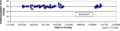
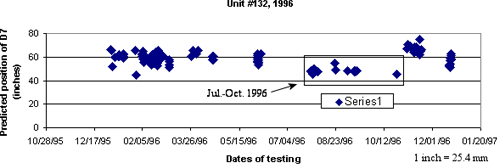
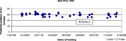
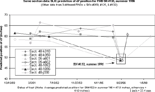
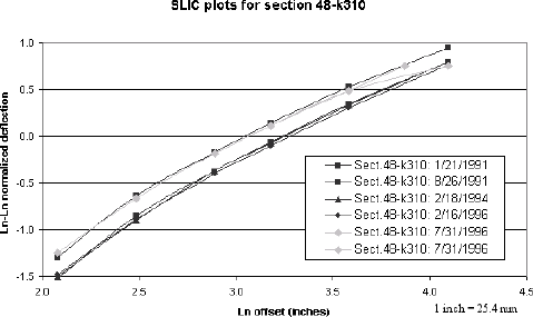
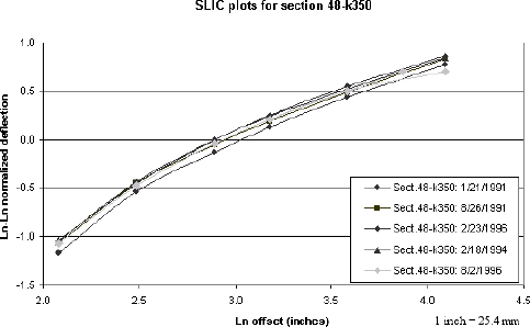
Study of Long-Term Pavement Performance (LTPP): Pavement Deflections

Appendix I. FWD SN 132, July 29, 1996–October 25, 1996

This previously reported sensor position error was located in the database using an automated screening version of SLIC. This screening version is tailored for sensor 7 (among others), with a close to zero overall bias and the best possible precision (see appendix B). The first three graphs shown in this appendix (see figures 38, 39, and 40) are plots of all the SN #132 d7 sensor position predictions during 1995 to 1997 for lane 1, drop height 4 FWD tests. In these graphs, it can be seen that the average prediction for this 3-year period, excepting the data for the dates in question, was around 152.4 cm (60 inches), as expected. However, during the period of time in question (July 29, 1996 to October 25, 1996), the average predicted position of d7 is clearly around 121.9 cm (48 inches) (average SLIC prediction for all flagged test dates = 122.2 cm (48.1 inches)). In fact, an empty sensor holder is generally positioned at 121.9 cm (48 inches).

In the fourth figure in this appendix, figure 41, it clearly can be seen that the SN #132 predicted positions for sensor 7 in mid-1996 are outliers relative to the predicted positions for sensor 7 when other (correctly configured) FWDs are used. For the seven test sections shown (from three different FWDs), on average the predicted position of d7 was 154.9 cm (61 inches) while the same prediction for SN #132 during the period of time in question was 121.4 cm (47.8 inches).

In the two figures that follow, figures 42 and 43, the same results are shown graphically, with the gray lines and data points showing the SLIC plots for d7 in both its actual (121.9 cm (48 inches)) and protocol but incorrect (152.4 cm (60 inches)) offset positions. The gray lines that are parallel to the rest of the lines are the correct plots, with d7 set to 121.9 cm (48 inches).

Because of this information, and the previous information supplied to FHWA, it can be concluded with certainty that d7 was positioned at 121.9 cm (48 inches) (or very close to 121.9 cm (48 inches)) on FWD SN #132 between July 29, 1996 and October 25, 1996. These dates correspond to the dates when lane 1 tests were conducted at drop height 4. This period of time may need to be extended slightly, if other tests were conducted along different lanes or at different drop heights. In any case, FWD tests conducted on or before June 6, 1996, and on or after November 5, 1996, clearly show d7 positioned at 152.4 cm (60 inches) (per protocol).

Figure 38. Graph. Predicted position of D7, unit 132, 1995. The figure is a scatter plot showing all serial number 132 D7 sensor position predictions for 1995. The X-axis is the date of testing and ranges from November 12, 1994, to February 5, 1996. The Y-axis is the predicted position of sensor D7 in inches and ranges from 0 to 80 inches parenthesis 0 to 203.2 centimeters end parenthesis. The sensor predictions in 1995 are mostly between 50 and 70 inches parenthesis 127 and 177.8 centimeters end parenthesis, with the average being approximately 60 inches parenthesis 152.4 centimeters end parenthesis. There is a gap with no data points between July and September.

Figure 38. Graph. Predicted position of d7, unit #132, 1995.

Figure 39. Graph. Predicted position of D7, unit 132, 1996. The figure is a scatter plot showing all serial number 132 D7 sensor position predictions for 1996. The X-axis is the date of testing and ranges from October 28, 1995, to January 20, 1997. The Y-axis is the predicted position of sensor D7 in inches and ranges from 0 to 80 inches parenthesis 0 to 203.2 centimeters end parenthesis. With the exception of the July to October timeframe, the sensor predictions in 1996 are mostly between 50 and 70 inches parenthesis 127 and 177.8 centimeters end parenthesis, with the average being approximately 60 inches parenthesis 152.4 centimeters end parenthesis. For the period July to October 1996, the average prediction is approximately 48 inches parenthesis 121.9 centimeters end parenthesis.

Figure 39. Graph. Predicted position of d7, unit #132, 1996.

Figure 40. Graph. Predicted position of D7, unit 132, 1997. The figure is a scatter plot showing all serial number 132 D7 sensor position predictions for 1997. The X-axis is the date of testing and ranges from December 1, 1996, to January 5, 1998. The Y-axis is the predicted position of sensor D7 in inches and ranges from 0 to 80 inches parenthesis 0 to 203.2 centimeters end parenthesis. The sensor predictions in 1997 are mostly between 50 and 70 inches parenthesis 127 and 177.8 centimeters end parenthesis, with the average being approximately 60 inches parenthesis 152.4 centimeters end parenthesis.

Figure 40. Graph. Predicted position of d7, unit #132, 1997.

Figure 41. Graph. Same section data for D7 position, three different falling weight deflectometers. The figure is a scatter plot illustrating predictions of D7 for three falling weight deflectometers, including serial number 132. The X-axis is the date of testing and ranges from October 19, 1989, to January 5, 1998. The Y-axis is the predicted position of sensor D7 in inches and ranges from 40 to 70 inches parenthesis 101.6 to 177.8 centimeters end parenthesis. With the exception of the testing by FWD serial number 132 around August 23, 1996, the predictions for the period ranged from 57 to 67 inches parenthesis 144.78 to 170.18 centimeters end parenthesis. The average prediction for the testing by FWD serial number 132 around August 23, 1996, was approximately 48 inches parenthesis 121.9 centimeters end parenthesis.

Figure 41. Graph. Same section data for d7 position, three different FWDs.

Figure 42. Graph. SLIC plots for section 48–k310 including unit number 132, July 1996.The figure is a line graph showing the SLIC plots for falling weight deflectometer testing on section 48–k310 on five different test dates. The X-axis is the natural logarithm of the offset in inches and ranges from 2.0 to 4.5 inches parenthesis 5.2 to 11.4 centimeters end parenthesis. The Y-axis is the natural logarithm, positive or negative, of the normalized deflection, and ranges from minus 1.5 to 1.0. With the exception of the testing by FWD serial number 132 on July 31, 1996, the plots are close to linear, almost parallel to each other, and rise from left to right. The plot for the testing by FWD serial number 132 on July 31, 1996, is divided into two parts. One part, which plots the correct data, is parallel to the other plots. The other part, which plots the incorrect data, is identical to the first part for most of the first part’s length but then flattens.

Figure 42. Graph. SLIC plots for section 48–k310 including unit #132, July 1996.

Figure 43. Graph. SLIC plots for Section 48–k350 including unit number 132, August 1996. The figure is a line graph showing the SLIC plots for falling weight deflectometer testing on section 48–k350 on five different test dates. The X-axis is the natural logarithm of the offset in inches and ranges from 2.0 to 4.5 inches parenthesis 5.2 to 11.4 centimeters end parenthesis. The Y-axis is the natural logarithm, positive or negative, of the normalized deflection, and ranges from minus 1.5 to 1.0. With the exception of the testing by FWD serial number 132 on August 2, 1996, the plots are close to linear, almost parallel to each other, and rise from left to right. The plot for the testing by FWD serial number 132 on August 2, 1996, is divided into two parts. One part, which plots the correct data, is parallel to the other plots. The other part, which plots the incorrect data, is identical to the first part for most of the first part’s length but then flattens.

Figure 43. Graph. SLIC plots for section 48–k350 including unit #132, August 1996.

Previous | Table of Contents | Next


Federal Highway Administration | 1200 New Jersey Avenue, SE | Washington, DC 20590 | 202-366-4000
Turner-Fairbank Highway Research Center | 6300 Georgetown Pike | McLean, VA | 22101