U.S. Department of Transportation
Federal Highway Administration
1200 New Jersey Avenue, SE
Washington, DC 20590
202-366-4000
Federal Highway Administration Research and Technology
Coordinating, Developing, and Delivering Highway Transportation Innovations
 |
| This report is an archived publication and may contain dated technical, contact, and link information |
|
Publication Number: FHWA-HRT-05-150
Date: February 2006 |
|||||||||||||||||||||||||||||||||||||||||||||||||||||||||||||||||||||||||||||||||||||||||||||||||||||||||||||||||||||||||||||||||||||||||||||||||||||||||||||||||||||||||||||||||||||||||||||||||||||||||||||||||||||||||||||||||||||||||||||||
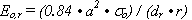
Review of The Long-Term Pavement Performance (LTPP) Backcalculation ResultsChapter 3. Forwardcalculation MethodologyBACKGROUND AND PREVIOUS DEVELOPMENTSClosed-form solutions for determining select layered-elastic properties of pavement systems have been used extensively in the past. In 1884, Boussinesq developed a set of closed-form equations for a semi-infinite, linear elastic median half-space, including the modulus of elasticity of the median, based on a point load. Subsequent study has shown that the apparent or composite subgrade modulus derived from any FWD sensor at offset "r" can be calculated from the equation in Figure 1:(5)
Figure 1. Equation. Composite subgrade modulus at an offset.
The suggested constant of 0.84 assumes that Poisson’s ratio is
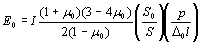
0.4 (from the calculation 1- Subsequent developments have allowed the use of the shape of the deflection basin to estimate various layered elastic (or slab-on-dense-liquid) moduli from FWD deflection readings. CENTERLINE SUBGRADE MODULUS BASED ON THE HOGG MODELOne method to ascertain the approximate subgrade stiffness, or elastic modulus, directly under an imposed surface load is the Hogg model. The Hogg model is based on a hypothetical two-layer system consisting of a relatively thin plate on an elastic foundation. The method in effect simplifies the typical multilayered elastic system with an equivalent two-layer stiff-layer-on-elastic foundation model. Depending on the choice of values along the deflection basin used to calculate subgrade stiffness, the tendency exists to either over- or underestimate the subgrade modulus. The Hogg model uses the deflection at the center of the load and one of the offset deflections. Hogg showed that the offset distance where the deflection is approximately one-half of that under the center of the load plate was effective at removing estimation bias. His calculations consider variations in pavement thickness and the ratio of pavement stiffness to subgrade stiffness, since the distance to where the deflection is one-half of the deflection under the load plate is controlled by these factors. The underlying model development for a finite subgrade was first published in 1944.(6) The implementation of the model used in this study was published in 1983.(7) The equations are as follows:
Figure 2. Equation. Hogg subgrade modulus.
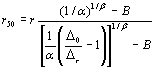
Figure 3. Equation. Offset distance where deflection is half of center deflection.
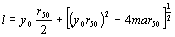
if Figure 4. Equation. Characteristic length of deflection basin.
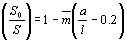
if Figure 5. Equation. Theoretical point load stiffness/pavement stiffness ratio. where:
Wiseman (7) described the implementation of the Hogg model using three cases. One is for an infinite elastic foundation, and the other two cases are for a finite elastic layer with an effective thickness that is assumed to be approximately 10 times the characteristic length, l. The two finite thickness cases are for fixed Poisson’s ratios of 0.4 and 0.5, respectively. Figure 1 shows the various constants used for the three versions of the Hogg model.
Case II of the Hogg model, used for the past 15 years, has been found to be reasonably stable on a wide variety of pavement types and locations, tending toward high correlation with backcalculated subgrade moduli but with significantly lower (and more conservative) results than the corresponding backcalculated values. This difference is because of apparent or actual subgrade nonlinearity (effectively, stress-softening) and/or a finite depth of subgrade (as calculated by Case II) to a semirigid bottom layer of subgrade material. In addition, less variation is indicated between FWD test points when the Hogg model of forwardcalculation is used, as compared to virtually any backcalculation approach. This phenomenon is examined in the subgrade screening results in chapter 4. Both as a screening tool and to derive relatively accurate, in situ subgrade stiffnesses, the Hogg model is effective and very easy to use compared to others and thus Case II is the recommended method to calculate subgrade moduli in forwardcalculation. BOUND SURFACE COURSE MODULUS BASED ON THE AREA METHODA viable method to determine the apparent surface course stiffness of the upper-most bound layer(s), under an imposed surface load is called the AREA (or quasi-radius of curvature) approach. This approach was first introduced in NCHRP Study 20-50(09), LTPP Data Analysis: Feasibility of Using FWD Deflection Data to Characterize Pavement Construction Quality.(3) More recently, the equations originally suggested have been updated and calibrated for AC and PCC pavement surfaces. For both pavement types, the radius of curvature method is based on the AREA concept (a deflection basin curvature index) and the overall composite modulus of the entire pavement structure, Eo, as the equation in Figure 6 shows.
Figure 6. Equation. Composite modulus under FWD load plate.
The equation in Figure 6 has been extensively used over the past three to four decades. A 1987 textbook by P. Ullidtz(5) gives an excellent introduction to this approach. Figure 6 is the most commonly used version of this equation. In theory, it is based on an evenly distributed and uniform FWD load and a Poisson's ratio of 0.5. Generally, Poisson's ratio will be less than 0.5 (usually thought to be between 0.15 and 0.20 for PCC layers and between 0.3 and 0.5 for most other pavement materials), while the distribution of the load under the FWD plate will not be exactly uniform (rather it will be somewhat nonuniform because of the rigidity of the loading plate). These two offsetting factors have resulted in the widely used and straightforward 1.5 times composite modulus formula, which was therefore chosen to develop the forwardcalculation spreadsheets. AREA, used for rigid pavements in this study, and as reported by AASHTO in 1993, is calculated as:(8)
Figure 7. Equation. 914-millimeter (mm) (36-inch) AREA equation for rigid pavements.
When calculating AREA36, the diameter of the loading plate must be between 300 mm (11.8 inches) and 305 mm (12 inches). An AREA36 calculation of 36 is achieved if all four deflection readings, at the 0-, 305-, 610-, and 914-mm (0-, 12-, 24-, and 36-inch) offsets are identical, which is equivalent to an infinitely stiff upper layer. While the equation in Figure 7 has been found to be well suited for rigid pavements with a large radius of curvature, flexible pavements generally have a much smaller radius of curvature (i.e., a steeper deflection basin). Accordingly, for AC pavements a new version of the AREA concept based on FWD sensors placed at 0-, 203-, and 305-mm (0-, 8-, and 12-inch) offsets was derived:
Figure 8. Equation. 305-mm (12-inch) AREA equation for flexible pavements.
An AREA12 calculation of 12 is achieved if all three deflection readings, at the 0-, 203-, and 305-mm (0-, 8-, and 12-inch) offsets, are identical, which is equivalent to an infinitely stiff upper layer (never very close to this value for flexible pavements, however). A series of calculations were made for AC and PCC pavement types to see what the AREA term becomes if all layers in a multilayered elastic system have identical stiffnesses or moduli (and Poisson’s ratios). This can be calculated using, for example, the CHEVRON, CHEVLAY2, ELSYM5, or BISAR multilayered elastic programs (CHEVLAY2 was used in this case). It turns out that, no matter which modulus value is selected, as long as all of the layers are assigned the same identical modulus of elasticity, the AREA36 term is always equal to 11.04 for rigid pavements (assuming no bedrock) and AREA12 is always equal to 6.85 if bedrock is assumed for flexible pavements. (Note: The AREA12 calculation for identical moduli with no bedrock = 6.91, close in value.) The reason that bedrock was assumed for AC and not PCC pavements is that FWD deflection readings generally reflect the presence of an underlying stiff layer for flexible pavements, but not for rigid pavements. Using either approach, however, the resulting calculations for upper layer pavement stiffness will be nearly the same, whether or not bedrock is assumed. The minimum AREA values of 11.04 and 6.85 for the 914-mm (36-inch) and 305-mm (12-inch) areas, respectively, are important in the following equations because they can now be used to ascertain whether the upper layer has a significantly higher stiffness than the underlying layer(s), and to what extent this increase affects the stiffness of the upper, bound pavement layers. For example, if the AREA36 term is much larger than 11.04, then the concrete layer is appreciably stiffer than the underlying (unbound) layer(s). The value 11.04 is therefore used in Figure 9, while Figure 10 can be considered as a radius of curvature stiffness index, based on the stiffness of the bound upper layer(s) compared to the composite stiffness of the underlying unbound layers. The calculation of Eo was previously explained in connection with the presentation of Figure 6, as a composite, effective stiffness of all the layers under the FWD loading plate. If these two terms are combined so that the boundary conditions are correct and the logic of the two AREA concepts are followed for PCC and AC pavements, the following equations result:
Figure 9. Equation. AREA factor for rigid pavements.
Figure 10. Equation. AREA factor for flexible pavements.
Figure 11. Equation. Stiffness or modulus of the upper PCC layer.
Figure 12. Equation. Stiffness or modulus of the upper AC layer.
Both Figure 11 and Figure 12 have been calibrated using a large number of trial CHEVLAY2 runs, and they work very well for typical pavement materials and moduli ratios. However, this approach is empirical rather than totally rigorous or scientific. Thus this method can be used effectively to approximate the relative stiffness of the upper (bound) layer(s) in a pavement cross section for QC, comparative, or routine testing and analysis. The advantage of using the equations in Figure 9 through Figure 12 or similar equations developed elsewhere is that forwardcalculation techniques, together with commonly used deflection-based quantities (such as AREA), can be combined. Only the composite modulus or stiffness of the pavement system, the AREA, and the pavement thickness normalized to the diameter of the loading plate are needed to calculate the relative stiffness of the bound upper layer(s) of pavement. INTERMEDIATE LAYER MODULUS CALCULATIONSForwardcalculation techniques, as discussed in chapter 3, for the subgrade and bound surface courses, can in turn be used in a pseudobackcalculation manner to derive the approximate stiffness of the intermediate layer, or layers, situated between the subgrade and bound surface course. Alternatively, the modulus relationship developed by Dorman and Metcalf between two adjacent layers of unbound materials can be used.(9) This method computes the base modulus as shown by Figure 13:
Figure 13. Equation. Modulus of the unbound base layer using the Dorman and Metcalf relationship.
Some philosophical issues exist with this quasi-backcalculation approach. The most important is that the calculations of the surface course modulus and the centerline subgrade modulus, as outlined in chapter 3, are virtually independent of one another and usually use different deflection sensors (except the center deflection) to derive the appropriate forwardcalculated values. Thus, when the center deflection is once again used to close the multilayered system by matching up the total center deflection with the pair of surface course and subgrade modulus values, the base course modulus so derived will be the least reliable of the three. Accordingly, the trial data used in phase I for the 15 flexible sections chosen for the pilot study were a matrix of forward- and backcalculated values shown in Table 2. For PCC sections, only the surface course and the subgrade were forwardcalculated by the two-layer variable method used in the backcalculation process from the LTPP database.
In summary, using forwardcalculated modulus data is not intended to replace backcalculation or any other form of modulus of elasticity measurements. Forwardcalculation, like all other methods of determining apparent, in situ stiffnesses or moduli merely gives the engineer estimates of these values. The only question is: How realistic are such estimates for pavement evaluation or design? Accordingly, forwardcalculation is designed for routine FWD-based project use and for screening purposes for moduli derived using other methods, especially backcalculation. The present study attempts to determine which of the backcalculated modulus values in the LTPP database—which are also estimates—are reasonable, since two distinctly different methods of deriving stiffnesses or moduli from the same FWD load-deflection data should not produce vastly dissimilar results.
FHWA-HRT-05-150
|
|||||||||||||||||||||||||||||||||||||||||||||||||||||||||||||||||||||||||||||||||||||||||||||||||||||||||||||||||||||||||||||||||||||||||||||||||||||||||||||||||||||||||||||||||||||||||||||||||||||||||||||||||||||||||||||||||||||||||||||||