Long-Term Pavement Performance Program Falling Weight
Deflectometer Maintenance Manual
Chapter 4. Strike Plate, Load Cell, Raise/Lower Assembly
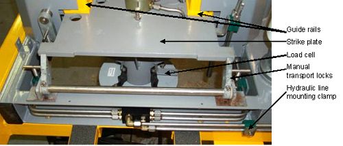
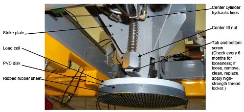
Figure 90 shows the strike plate, load cell, and the raise/lower
assembly.
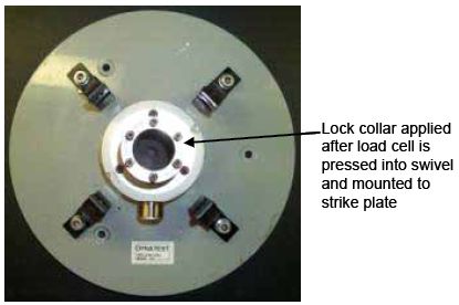
Figure 90. Load cell mounted to the
strike plate.
STRIKE PLATE
The strike plate (figure 91) requires routine cleaning and
semiannual visual inspection of the welds. The following components
should also be checked annually or as indicated:
- Load cell and mounting bracket.
- Center cylinder mounting nut.
- Hydraulic line mounting clamps.
- Rear raise/lower bar shaft and mounting bracket.
- Guide profile rails. Check cap screws every 3 to 6 months.
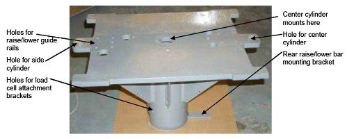
Figure 91. Strike plate.
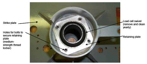
The load cell swivel and retaining plate are located on the
bottom of the strike plate (figure 92). Figure 88 shows a different
view of the raise/lower car mounting bracket. Check bolts annually
and apply medium-strength thread locker. Annually remove the load
cell swivel and clean.
Figure 92. Bottom view of load cell
swivel and retaining bracket on strike plate.
LOAD CELL
The load cell attaches to the strike plate, and the load cell
swivel is pressed in to fit in the strike plate, making a snug fit.
The following illustrations show the steps taken during a major
overhaul of a load cell:
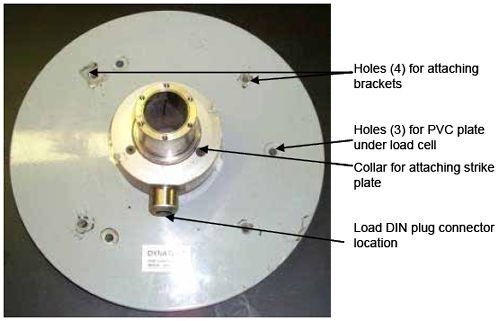
- Place the load cell base down (figure 93).
Figure 93. Load plate (base
down).
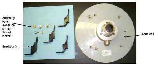
- Attach the mounting brackets (figures 94 and 95). The brackets
should be checked annually. Make sure all bolts are in place and
the rubber is not torn.
Figure 94. Load plate with mounting
brackets.
Figure 95. Load cell with brackets
mounted.
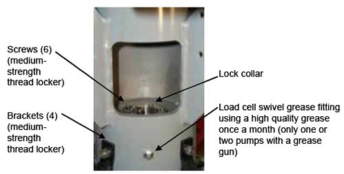
- Attach the load cell to the strike plate by using a guide tool
to center the load cell on the swivel collar, which is essential
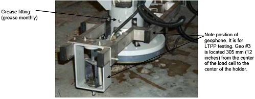
for correct alignment (figure 96). Grease the load cell swivel
monthly. It does not require a large amount of grease; one
or two pumps from a hand-held grease gun with high-grade grease are
sufficient. Failure to grease the load cell swivel can result in
load cell calibration errors.
Figure 96. Mounting brackets and lock
flange attached to strike plate.
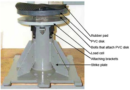
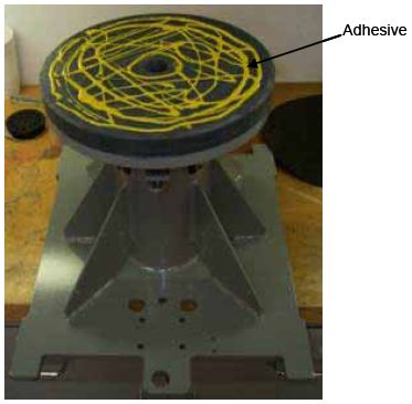
- Assemble the rubber pad and PVC disk before installing them on
the load cell (figure 97). Use a strong adhesive to secure the
rubber pad to the PVC disk before screwing the PVC disk to the load
cell. Secure the PVC disk and rubber pad to the bottom of the load
cell (figure 98).
NOTE: Photos here are part of a major overhaul. It is
recommended that if a load cell replacement is necessary that the
rubber pad and PVC disk be put together before installing on the
load cell. After replacing a load cell, conduct a full, absolute
calibration.
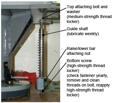
- Attach the rear raise/lower bar guide to the front of the
strike plate. The bottom screw tends to work loose; check it
annually. Use a high-strength thread locker to secure the screw.
The bottom screw can be difficult to remove. It may be necessary to
apply heat to the bolt to remove it.
Figure 97. Strike plate with attached
load cell and pad (shown inverted).
Figure 98. Adhesive applied to PVC
disk.
RAISE/LOWER BAR
The raise/lower bar guide raises and lowers the geophone rail to
the ground. The raise/lower box sleeve in the front of the trailer
guides the front end (figure 99).
Figure 99. Raise/lower bar guide location
before assembly(rear).
The rear end of the raise/lower bar attaches to the rear lift
nut (figure 100).
Figure 100. Raise/lower bar guide during
assembly.
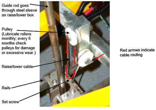
A steel cable and pulleys raise and lower the bar (figure 101).
Lubricate the front raise/lower pulleys monthly and check the cable
every 3 to 6 months for damage. Replace it if damaged.
Note: The bottom screw tends to work loose so it is a good idea to
check annually. Use high strength lock tight to secure the
screw.
Figure 101. Raise/lower bar guide in
location.
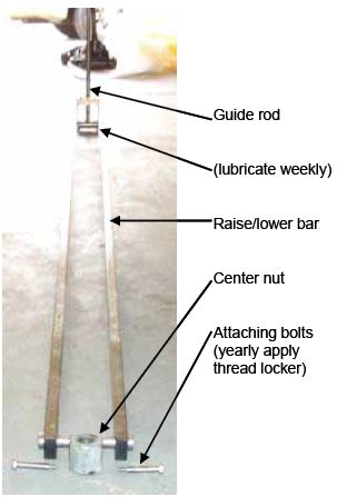
Figure 102 shows the raise/lower bar removed from the FWD, and
figure 103 shows the center lift nut and attaching bolts. Little
maintenance is required. Yearly, remove the attaching bolts on the
rear, clean, and reapply with medium-strength thread locker.
Figure 102. Raise/lower bar.
Figure 103. Center lift nut and attaching
bolts.
Following are the steps to assemble the raise/lower bar:
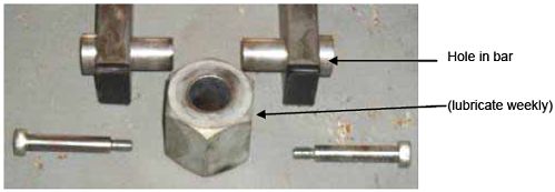
- Install the center lift nut over the guide shaft. Place the
guide shaft between the strike plate and the lower tab as seen in
figure 101. After installing this component, assemble the
raise/lower bar. Align the hole in the rear bar with the hole in
the rear lift nut. Apply medium-strength thread locker to the bolt.
Repeat on the opposite side.
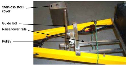
- Attach the cable-pulley configuration to the trailer frame
(figures 104). Attach a steel cable and run it through two pulleys
(figure 105). Lubricate the pulleys monthly with silicone spray.
Periodically remove the cover and inspect components for damage or
excess wear, and repair or replace as necessary.
Figure 104. Closeup of cable
connection.
Figure 105. Raise/lower bar, guide rod,
and attaching cable.
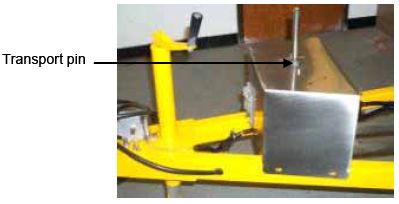
- Place stainless steel cover over guide rod (figure 106). Make
sure the pin is in place during transport.
Figure 106. Raise/lower
cover.
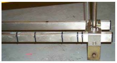
- Attach the cable to the top of the rails with straps (figure
107).
Figure 107. Attached cable.
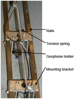
- Attach the tension spring (figure 108). The tension spring
helps take up cable slack on the top of the raise/lower bar when
the bar is fully raised.
Figure 108. Mounted geophone holders to
raise/lower bar.
- The geophone holders are screwed into specific locations along
the rails, although the locations can be adjusted. Mount the
geophone holders to the raise/lower bar and adjust position
(figures 109 and 110).
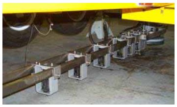
Figure 109. Completed assembly of
raise/lower bar.
Figure 110. Rear view of raise/lower
assembly.
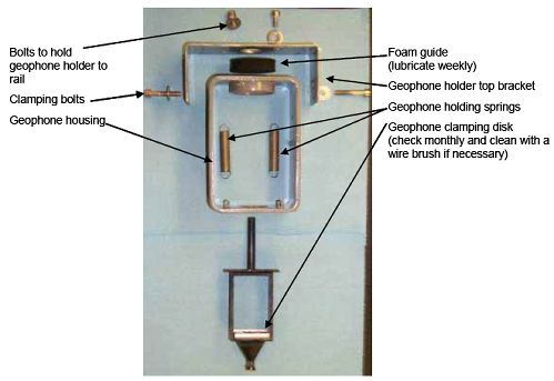
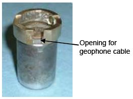
GEOPHONE HOLDER
The geophone holder attaches to the raise/lower bar on the FWD.
The purpose of the geophone holder is to provide a means of
adjusting the geophones to various distances from the load
plate.
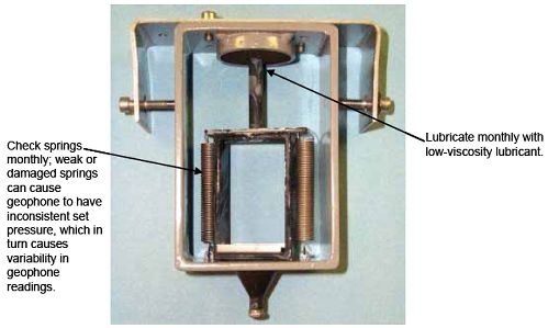
Figure 112 shows geophone holder components. Upon inspection, if
holder springs are weak or damaged replace only as a set, not
individually, to maintain proper seating pressure.
Figure 111. Geophone holder
components.
Geophones are preassembled. Figure 112 shows an assembled
geophone holder for an 80 mil (2,032 microns) standard
geophone.
Figure 112. Assembled geophone
holder.
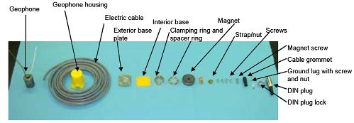
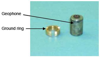
Figure 113 shows the components for the geophone.
Figure 113. Geophone
components.
Use the following steps to assemble your own geophone rather
than using a preassembled one:
- Mount the ground ring to the geophone (figures 114 and
115).
Figure 114. Ground ring and
geophone.
Figure 115. Mounted ground
ring.
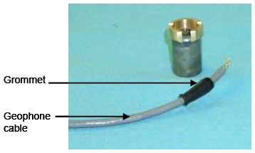
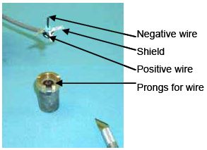
- Prepare the geophone cable for assembly. Use a sharp art knife
to split the two-strand wire and shield. Separate the wires to
solder them onto the geophone (figures 116 and 117).
Figure 116. New geophone
cable.
Figure 117. Separated wire.
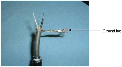
- Twist the wire shield and attach to the ground lug (figure
118).
Figure 118. Attached ground
lug.
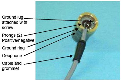
- Solder the positive and negative wires to the appropriate
prongs on the geophone (figure 119). Screw the ground lug into the
side to the ground ring.
Figure 119. Geophone cable soldered to
geophone.
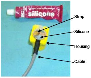
- Place the geophone in the geophone housing and fill the
internal area with electronics-grade silicone (figure 120). Install
the strap.
Figure 120. Silicone-filled
housing.
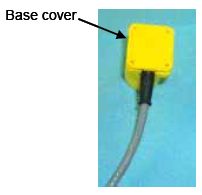
- Place the plastic base cover on the geophone (figure
121).
Figure 121. Base cover on
housing.
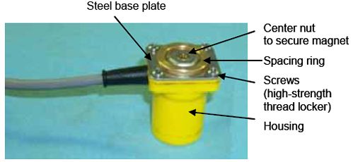
- Attach the steel base plate, which will secure the magnet to
the geophone housing (figure 122).
Figure 122. Geophone with base plate
attached.
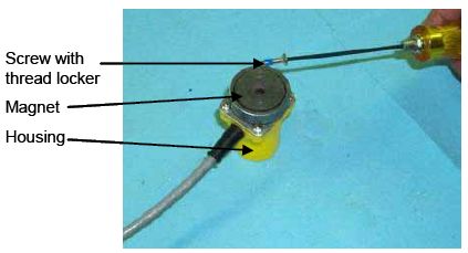
- Attach the magnet with a screw and medium-strength thread
locker (figures 123 and 124).
Figure 123. Attached magnet.
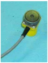
Figure 124. Completely assembled
geophone.
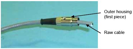
- Pay attention to the DIN (Deutsches Institut fur Normung eV)
plug connector at the other end of the geophone cable (figure 125).
Attach the DIN plug housing to the end of the cable.
Figure 125. Raw cable and DIN plug
housing.
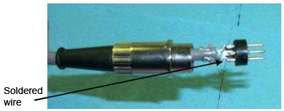
- Solder wires to the internal component of the DIN plug (figure
126).
Figure 126. Internal view of the DIN
plug.
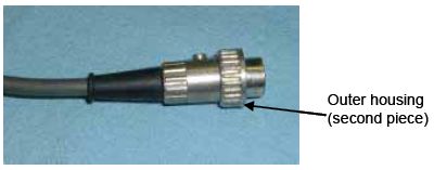
- Attach the second half of the DIN plug outer housing to the
plug (figure 127).
Figure 127. Completed DIN
plug.
After the geophone is assembled, plug the geophone into the
correct DIN connector and run a drift screen check to ensure they
are functioning properly). Follow by conducting a reference
calibration.