U.S. Department of Transportation
Federal Highway Administration
1200 New Jersey Avenue, SE
Washington, DC 20590
202-366-4000
Federal Highway Administration Research and Technology
Coordinating, Developing, and Delivering Highway Transportation Innovations
 |
| This report is an archived publication and may contain dated technical, contact, and link information |
|
Publication Number: FHWA-HRT-05-153
Date: December 2006 |
|
Long-Term Pavement Performance Program Falling Weight Deflectometer Maintenance ManualChapter 5. ElectronicsPROXIMITY SWITCHESThere are four proximity switches (figure 128):
Figure 128. Four types of proximity switches. 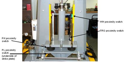 ELECTRICAL CONNECTION BOXCheck electrical connections and clean annually (figure 129). Refer to the manufacturers wiring schematics and owner’s manual for further information on the wiring diagram. Figure 129. Electronics connection box. 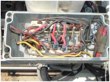 SYSTEM PROCESSORAnnually remove the system processor (figure 130) and clean all internal components. Periodically check connections in the rear of the processor (figure 131) to make sure they are secure and no strain is put on the cables. Also, check that the processor is securely mounted to the vehicle. Refer to the manufacturer’s owner’s manual for repairs and maintenance beyond the routine. Figure 130. System processor. 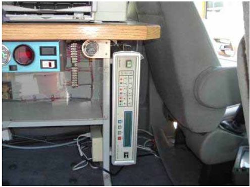 Figure 131. Rear view of vertically mounted system processor. 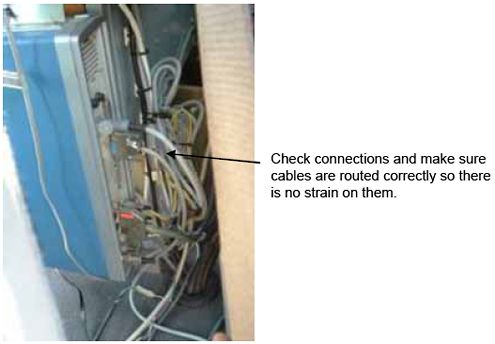 DMI PROXIMITY SWITCHThe vehicle-mounted proximity switch is a distance-measuring instrument (DMI) (figure 132). It should be checked monthly to make sure the correct air gap is used. Stainless switches can have a sensor gap of up to 8 mm (0.315 inch). The yellow plastic switches can have a gap of up to 5 mm (0.197 inch). Monthly check the wiring and switches to make sure there is no strain on the cable. Visually check the switch for damage and replace if necessary. Recalibrate after repairs are made. Figure 132. Vehicle-mounted proximity switches. 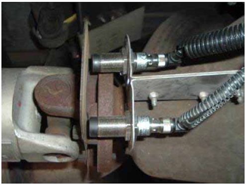 VEHICLE CHARGE PLUG CONNECTIONMonthly clean the power supply connection between the vehicle and trailer (figure 133). Also, check that the connection is snug to make good contact between the two plugs (figure 134). Figure 133. Vehicle charge plug. 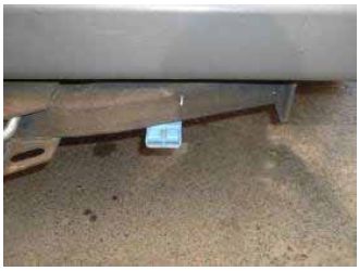 Figure 134. Trailer-to-vehicle charge plug. 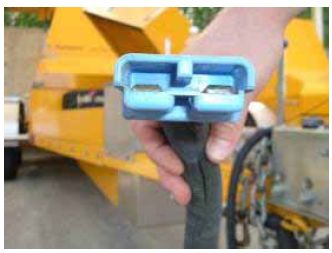 POWER CONTROL BOARDThe power control board is located behind the panel shown in figure 135. Remove the front panel and inspect all connections, making sure they are tight. Clean all connections annually. Figure 135. Power control box (board behind front panel). 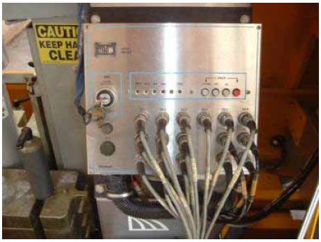 FUSE BLOCKSFigure 136 shows the trailer fuse block. Two more fuse blocks are located inside the vehicle. All three fuse blocks should be inspected and cleaned monthly. Figure 136. Trailer fuse block. 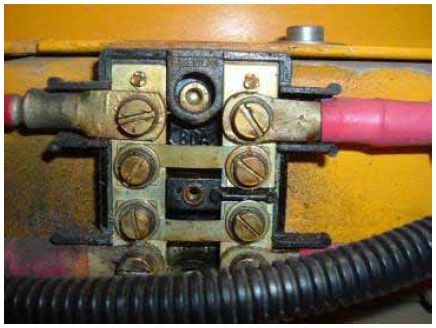 ELECTRONICS BATTERYThe electronics battery is located inside the vehicle (figure 137). Check that it is securely mounted to the vehicle floorboard, and check and clean the connections monthly. Also, check the water level inside the battery. If water needs to be added, use distilled water. Figure 137. Electronics battery inside the vehicle. 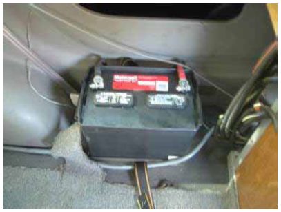
|

