Falling Weight Deflectometer Calibration Center and Operational Improvements: Redevelopment of The
Calibration Protocol and Equipment
APPENDIX E. SPECIFICATIONS AND DRAWINGS
SPECIFICATIONS
1. General specifications
1.1 Description
The FWD calibration hardware set includes one accelerometer box assembly, one geophone calibration stand assembly, one seismometer calibration stand assembly, one reference load cell assembly, and one ball-joint anchor assembly. In some cases, only one of the stands is ordered for a hardware set. Drawings of each item are included by reference as part of this specification. Table 13 shows a list of drawings for each assembly.
Table 13. Parts required for one hardware set.
| Assembly |
Drawing Number |
| Accelerometer box assembly |
CLRP-AB01 |
| Ball-joint anchor assembly |
CLRP-BJ01 |
| Geophone stand assembly1 |
CLRP-GCS01 |
| Seismometer stand assembly1 |
CLRP-SCS01 |
| Geophone adapters assembly |
CLRP-GA01 |
| Reference load cell assembly |
CLRP-LC01 |
1Indicates that in some cases, only one stand is ordered for a
hardware set. |
1.2 Materials
The required materials are described in the referenced drawings (see table 13).
1.3 Manufacturing Requirements/Conflicts
The contractor should provide all materials needed to manufacture one complete hardware set unless otherwise noted.
Additional manufacturing requirements are listed with the specifications for each individual
part or subassembly. If there is a conflict between the drawings and the specifications, the specifications should govern.
1.4 Surface Smoothness
An industrial quality surface finish is desired. All machined surfaces should have a smoothness of 63 μ-inches (0.0016 mm) or less.
1.5. Mill Surface Finish
The mill surface finish on aluminum extrusions should be inspected for nicks, cuts, and dings, and a reasonable effort should be made to smooth out the defects before anodizing. Avoid removal of excessive amounts of material in this process.
1.6 Anodizing
Where anodizing is required on aluminum parts, all parts should be thoroughly cleaned and anodized according to MIL-A-8625F Type 2 Class 2 (Black). All parts should have a cosmetically homogeneous appearance after being anodized.
If for any reason parts must be stripped to remove the anodizing, a phosphoric chromic solution should be used, followed by surface polishing to remove pitting and achieve a 63-μ-inch
(0.0016-mm) smoothness.
1.7 Loctite®
Where Loctite® is required, medium strength #242 Loctite® should be used.
1.8 Delivery/Acceptance
The contractor should provide a guaranteed delivery time. All parts should be assembled and delivered to the address provided by the purchasing agency.
The purchasing agency should have 7 days after delivery to check parts for proper alignment and fit as well as finish, as required. If the part or parts are not acceptable, the contractor should replace them at no additional charge.
1.9 Method of Payment
Payment should be authorized upon acceptance of the complete order.
2.0 Accelerometer Box Assembly Specifications (Drawing CLRP-AB01)
2.1 Description
The accelerometer box assembly is designed to house a Silicon Designs Model 2220 accelerometer as well as to provide some EMI shielding and additional physical protection. The box assembly mounts on the calibration platter, the geophone calibration stand, and the seismometer calibration stand by means of two #10-24 knurled head thumbscrews through the lip on the box.
2.2 Materials
All of the materials for the accelerometer box assembly are described in the referenced drawing and the bill of materials.
2.3 Manufacturing Requirements
The accelerometer box top and bottom, the box assembly, and calibration platter should be assembled together to ensure proper alignment prior to delivery to the customer. The accelerometer box top and bottom should also be fitted into the geophone calibration stand and the seismometer calibration stand, and the fit should be a firm coupling to both stands without any gaps or interference between mating surfaces.
Each aluminum part should be cleaned and then anodized in accordance with section 1.5. Upon delivery, the customer should finish assembly of the box by mounting the accelerometer and the Amphenol receptacle, mating the box top and bottom, mounting the bubble level, and attaching the leveling screws to the calibration platter.
3.0 Ball-joint Anchor Assembly Specifications (Drawing CLRP-BJ01)
3.1 Description
The ball-joint anchor assembly is the means by which the calibration stands are coupled to the test pad during FWD calibration. The clamp provides a solid mechanical connection to the calibration stand, and the Techno/Sommer KG60 ball-joint provides some rotational freedom, making the stands easier to use as well as providing for some moment compensation.
3.2 Materials
All of the materials for the ball-joint anchor assembly are described in the referenced drawing and the bill of materials.
3.3 Manufacturing Requirements
Upon delivery, the customer should finish assembly of the anchor by attaching the base bar and the clamp base to the ball-joint. The clamp should be attached to the clamp base, and the rest stop should be mounted to the anchor assembly.
4.0 Geophone Calibration Stand Assembly Specifications (Drawing CLRP-GCS01)
4.1 Description
The geophone calibration stand assembly is designed to hold up to 10 geophones from the Dynatest®, Carl Bro, KUAB, or JILS FWD. The accelerometer box (see section 2.0) mounts to the middle shelf in the stand. The stand is attached to the ball-joint anchor (see section 3.0) during the calibration procedure.
4.2 Materials
All of the materials for the geophone calibration stand are described in the referenced drawing and the bill of materials.
4.3 Manufacturing Requirements
Prior to welding the stand, the parts should be cleaned and dry fitted together. A qualified Tungsten inert gas (TIG) welder should perform all of the welding. After welding, the stand should be cleaned and then anodized in accordance with section 1.5.
After delivery, the customer should finish assembly by adding handles and bubble levels as needed and use Loctite® to keep the connector pin in place.
5.0 Seismometer Calibration Stand Assembly (Drawing CLRP-SCS01)
5.1 Description
The seismometer calibration stand assembly is designed to hold up to 10 KUAB seismometers in a 2-column configuration. Additionally, the accelerometer box (see section 2.0) mounts to the middle shelf in the stand. The stand is attached to the ball-joint anchor (see section 3.0) during the calibration procedure.
5.2 Materials
All materials for the seismometer calibration stand assembly are described in the referenced drawing and the bill of materials.
5.3 Manufacturing Requirements
Prior to welding the stand, the parts should be cleaned and dry fitted together. A qualified TIG welder should perform all of the welding. After welding, the stand should be cleaned and anodized in accordance with section 1.5.
After delivery, the customer should finish assembly by adding handles and bubble levels as needed and use Loctite® to keep the connector pin in place.
6.0 Geophone Adapter Specifications
6.1 Description
The geophone adapters are used to couple three different types of geophones to the geophone calibration stand (see section 4.0) and allow for ease of movement of the geophones within
the stand.
6.2 Materials
All materials for the geophone adapters are described in the referenced drawing and the bill
of materials.
6.3 Manufacturing Requirements
The geophone adapters should be dry fitted into the geophone calibration stand sensor shelves to ensure a loose sliding fit in the slotted hole on each shelf.
7.0 Reference Load Cell Assembly (Drawing CLRP-LC01)
7.1 Description
The reference load cell is a custom load cell designed specifically for FWD calibration. The load cell allows all brands of FWD to be calibrated with a 11.7-inch (300-mm) load plate.
7.2 Materials
All materials for the reference load cell assembly are described in the referenced drawings and bill of materials.
7.3 Manufacturing Requirements
Prior to welding the base to the body, the parts should be cleaned and dry fitted together. A certified TIG welder should perform all of the welding. After welding, the load cell parts should be cleaned and anodized in accordance with section 1.5, with the exception of the measuring links (Drawing CLRP-LC04), which should not be anodized.
After delivery, the customer should have the measuring links gauged by a qualified strain gauge installer. Then, the load cell should be fully assembled, conditioned, and calibrated according to AASHTO R33-03.(10)
COMPLETE DRAWING LIST
Table 14 provides a complete drawing list for the accelerometer box, ball-joint anchor, geophone calibration stand, seismometer calibration stand, geophone adapters, reference load cell, and data acquisition cables. The drawings follow in the same order in this appendix.
Table 14. Complete drawing list.
| Drawing Number |
Part Name |
| CLRP-AB01 |
Accelerometer box assembly |
| CLRP-AB02 |
Accelerometer box bottom |
| CLRP-AB03 |
Accelerometer box top |
| CLRP-AB04 |
Calibration platter |
| CLRP-AB05 |
Accelerometer wiring |
| CLRP-BJ01 |
Ball-joint anchor assembly |
| CLRP-BJ02 |
Clamp |
| CLRP-BJ03 |
Clamp base |
| CLRP-BJ04 |
Base bar |
| CLRP-BJ05 |
Rest stop |
| CLRP-GCS01 |
Geophone stand assembly |
| CLRP-GCS02 |
Geophone stand side rail |
| CLRP-GCS03 |
Geophone stand top shelf |
| CLRP-GCS04 |
Geophone stand bottom shelf |
| CLRP-GCS05 |
Geophone stand sensor shelf |
| CLRP-GCS06 |
Geophone stand accelerometer shelf |
| CLRP-GCS07 |
Geophone stand handle holder |
| CLRP-GCS08 |
Geophone stand connector pin |
| CLRP-SCS01 |
Seismometer stand assembly |
| CLRP-SCS02 |
Seismometer stand side rail |
| CLRP-SCS03 |
Seismometer stand top shelf |
| CLRP-SCS04 |
Seismometer stand sensor shelf |
| CLRP-SCS05 |
Seismometer stand standoff |
| CLRP-SCS06 |
Seismometer stand bottom shelf |
| CLRP-SCS07 |
Seismometer stand handle holder |
| CLRP-SCS08 |
Seismometer stand connector pin |
| CLRP-SCS09 |
Seismometer stand shelf subassembly |
| CLRP-SCS10 |
Seismometer stand accelerometer shelf |
| CLRP-SCS11 |
Seismometer stand accelerometer shelf subassembly |
| CLRP-GA01 |
Geophone adapter assemblies |
| CLRP-GA02 |
Carl Bro adapter |
| CLRP-GA03 |
JILS adapter |
| CLRP-GA04 |
KUAB adapter |
| CLRP-LC01 |
Load cell assembly |
| CLRP-LC02 |
Load cell body |
| CLRP-LC03 |
Base plate |
| CLRP-LC04 |
Measuring link |
| CLRP-LC05 |
Cover plate |
| CLRP-LC06 |
Foot |
| CLRP-LC07 |
Guide fingers |
| CLRP-LC08 |
Interior connector wiring |
| CLRP-LC09 |
Strain gauge layout |
| CLRP-LC10 |
Bridge wiring |
| CLRP-DAQ01 |
Vishay to DAQ cable |
| CLRP-DAQ01A |
Vishay 2310B BNC to DAQ cable |
| CLRP-DAQ01B |
Vishay 2310B BNC to DAQ cable—stock parts |
| CLRP-DAQ02 |
Vishay to load cell DAQ cable |
| CLRP-DAQ03 |
Accelerometer signal cable |
| CLRP-DAQ04 |
Pushbutton to KUSB DAQ cable |
| CLRP-DAQ06 |
KUSB protection wiring |
| CLRP-DAQ07 |
KUSB enclosure rear panel |
| CLRP-DAQ08 |
KUSB enclosure front panel |
ACCELEROMETER BOX
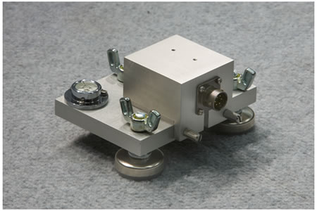
Figure 47. Photo. Accelerometer box.
Table 15. Fabricated parts required for BM-AB accelerometer box assembly.
| Drawing Number |
Description |
Quantity |
| CLRP-AB02 |
Accelerometer box bottom |
1 |
| CLRP-AB03 |
Accelerometer box top |
1 |
| CLRP-AB04 |
Calibration platter |
1 |
| CLRP-AB05 |
Accelerometer wiring |
1 |
Table 16. Hardware items required for BM-AB accelerometer box assembly.
| Vendor Part Number |
Item |
Vendor |
Quantity |
| 96877A209 |
Flat head Phillips machine screw, 18-8 SS, 4-40 thread, 3⁄8
-inch length, Mil Spec 51959-15 |
McMaster-Carr® |
4 |
| 91400A110 |
Pan head Phillips machine screw, 18-8 SS, 4-40 thread, ½-inch length, Mil Spec 51957-17 |
McMaster-Carr® |
2 |
| 91737A072 |
Fillister head Phillips machine screw,
18-8 SS, 4-40 thread, ¼-inch length |
McMaster-Carr® |
7 |
| 91746A876 |
Knurled head thumb screw, slotted, 18-8 SS, 10-24 thread, ½-inch length,
¼-inch head diameter, ½-inch length |
McMaster-Carr® |
2 |
| 91755A205 |
Retaining washer, Nylon 6/6, #4 screw size, 7⁄64-inch inside diameter, 17⁄64-inch outside diameter, 0.027–0.037-inch thickness |
McMaster-Carr® |
2 |
| 2198A85 |
Bull’s-eye level, glass, surface mount, center circle and cross lines, 1¼-inch base diameter, 7⁄16-inch height |
McMaster-Carr® |
1 |
| 23015T64 |
Leveling mount, polyethylene base,
3⁄8-inch 16 thread, 50 lbf maximum load, 1-inch length |
McMaster-Carr® |
3 |
| 98520A145 |
Locking wing nut, zinc alloy, nylon insert, 3⁄8-inch 16 screw size, 1½-inch wing spread |
McMaster-Carr® |
3 |
| 2220-005 |
Accelerometer, ± 5 g with calibration certificate |
Silicon Designs |
1 |
| 654-PT02A106P |
Amphenol receptacle, PT02A-10-6P |
Mouser Electronics |
1 |
1 inch = 25.4 mm
1 lbf = 4.45 N |
Table 17. Vendor contact information for BM-AB accelerometer box assembly.
| Vendor |
Web site |
Notes |
| McMaster-Carr® |
www.mcmaster.com |
See Web site for specific contact information located in the "About Us" section. |
| Silicon Designs |
www.silicondesigns.com |
1445 NW Mall St, Issaquah, WA 98027
425-391-8329 |
| Mouser Electronics |
www.mouser.com |
See Web site for specific contact information located in the "Contact Us" section. |
| Incodema |
www.incodema.com |
Incodema Inc.
407 Cliff Street, Ithaca, NY 14850
607-277-7070 |
Table 18. Hardware costs for BM-AB accelerometer box.
| Part |
Quantity |
Supplier |
Cost1 |
| Materials and machining |
1 |
Incodema |
$912.00 |
| Accelerometer (±5 g) |
1 |
Silicon Designs |
$580.00 |
| Miscellaneous hardware |
1 |
|
$38.00 |
1Indicates the cost in February 2009. |
Figure 48. Illustration. CLRP-AB01 accelerometer box assembly.
Figure 49. Illustration. CLRP-AB02 accelerometer box bottom.
Figure 50. Illustration. CLRP-AB03 accelerometer box top.
Figure 51. Illustration. CLRP-AB04 calibration platter.
Figure 52. Illustration. CLRP-AB05 accelerometer wiring.
BALL-JOINT ANCHOR
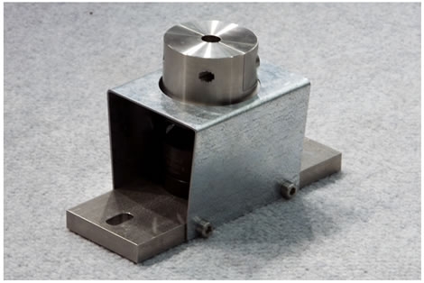
Figure 53. Photo. Ball-joint anchor
Table 19. Fabricated parts required for the BM-BJ ball-joint anchor assembly.
| Drawing Number |
Description |
Quantity |
| CLRP-BJ02 |
Clamp |
1 |
| CLRP-BJ03 |
Clamp base |
1 |
| CLRP-BJ04 |
Base bar |
1 |
| CLRP-BJ05 |
Rest stop |
1 |
Table 20. Hardware items required for the BM-BJ ball-joint anchor assembly.
| Vendor Part Number |
Item |
Vendor |
Quantity |
| KG-60 |
Ball-joint |
Techno/Sommer |
1 |
| 91292A145 |
Socket head cap screw, 18-8 stainless steel, M8 thread,
16-mm length, 1¼-mm pitch |
McMaster-Carr® |
6 |
| 91292A148 |
Socket head cap screw, 18-8 stainless, M8 thread, 25-mm length, 1 ¼-mm pitch |
McMaster-Carr® |
2 |
| 91292A135 |
Socket head cap screw, 18-8 stainless steel, M6 thread,
16-mm length, 1-mm pitch |
McMaster-Carr® |
4 |
1 inch = 25.4 mm |
Table 21. Vendor contact information.
| Vendor |
Web site |
Notes |
| Techno/Sommer |
www.techno-sommer.com |
See Web site for specific contact information located in the "Sales Representatives" section. |
| McMaster-Carr® |
www.mcmaster.com |
See Web site for specific contact information located in the "About Us" section. |
| Incodema |
www.incodema.com |
Incodema Inc.
407 Cliff Street, Ithaca, NY 14850
607-277-7070 |
Table 22. Hardware costs for BM-BJ ball-joint anchor.
| Part |
Quantity |
Supplier |
Cost1 |
| Materials and machining |
1 |
Incodema |
$919.00 |
| Techno/Sommer KG60 Ball-joint |
1 |
Techno/Sommer |
$143.00 |
| Miscellaneous hardware |
1 |
|
$31.00 |
1Indicates the cost in February 2009. |
Figure 54. Illustration. CLRP-BJ01 ball-joint anchor assembly.
Figure 55. Illustration. CLRP-BJ02 clamp.
Figure 56. Illustration. CLRP-BJ03 clamp base.
Figure 57. Illustration. CLRP-BJ04 base bar.
Figure 58. Illustration. CLRP-BJ05 rest stop.
GEOPHONE CALIBRATION STAND
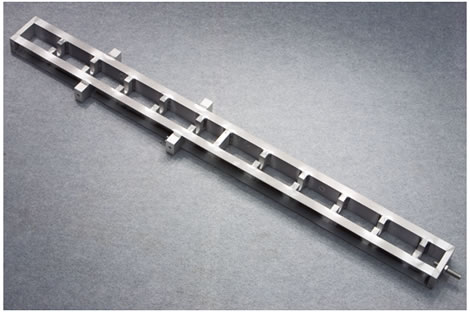
Figure 59. Photo. Geophone calibration stand.
Table 23. Fabricated parts required for BM-GCS geophone calibration stand assembly.
| Drawing Number |
Item |
Quantity |
| CLRP-GCS02 |
Geophone stand side rail |
2 |
| CLRP-GCS03 |
Geophone stand top shelf |
1 |
| CLRP-GCS04 |
Geophone stand bottom shelf |
1 |
| CLRP-GCS05 |
Geophone stand sensor shelf |
10 |
| CLRP-GCS06 |
Geophone stand accelerometer shelf |
1 |
| CLRP-GCS07 |
Geophone stand handle holder1 |
4 |
| CLRP-GCS08 |
Geophone stand connector pin2 |
1 |
1Identical to CLRP-SCS07.
2Identical to CLRP-SCS08.
|
Table 24. Hardware items required for BM-GCS geophone calibration stand assembly.
| Vendor Part Number |
Item |
Vendor |
Quantity |
| 62385K65 |
Tapered handle, Smooth phenolic, 3⁄8-inch, 16 x ½-inch threaded stud, 1-inch diameter |
McMaster-Carr® |
2 |
| 2198A85 |
Glass surface-mount bull’s-eye level center circle and cross lines, 1¼-inch base diameter, 7⁄16-inch height |
McMaster-Carr® |
1 |
| 91737A072 |
18-8 stainless steel fillister head Phillips machine screw 4-40 thread, ¼-inch length |
McMaster-Carr® |
3 |
1 inch = 25.4 mm |
Table 25. Vendor contact information for BM-GCS geophone calibration stand.
| Vendor |
Web site |
Notes |
| McMaster-Carr® |
www.mcmaster.com |
See Web site for specific contact information in the "About Us" section. |
| Incodema |
www.incodema.com |
Incodema Inc.
407 Cliff Street, Ithaca, NY 14850
607-277-7070 |
Table 26. Hardware costs for BM-GCS geophone calibration stand.
| Part |
Quantity |
Supplier |
Cost1 |
| Materials and machining |
1 |
Incodema |
$1407.00 |
| Miscellaneous hardware |
1 |
|
$30.00 |
1Indicates the cost in February 2009. |
Figure 60. Illustration. CLRP-GCS01 geophone stand assembly.
Figure 61. Illustration. CLRP-GCS02 geophone stand side rail.
Figure 62. Illustration. CLRP-GCS03 geophone top shelf.
Figure 63. Illustration. CLRP-GCS04 geophone stand bottom shelf.
Figure 64. Illustration. CLRP-GCS05 geophone stand sensor shelf.
Figure 65. Illustration. CLRP-GCS06 geophone stand accelerometer shelf.
Figure 66. Illustration. CLRP-GCS07 geophone stand handle holder.
Figure 67. Illustration. CLRP-GCS08 geophone stand connector pin.
SEISMOMETER CALIBRATION STAND
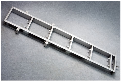
Figure 68. Photo. KUAB seismometer calibration stand.
Table 27. Fabricated parts required for BM-SCS seismometer calibration stand assembly.
| Drawing Number |
Description |
Quantity |
| CLRP-SCS02 |
Seismometer stand side rail |
2 |
| CLRP-SCS03 |
Seismometer stand top shelf |
1 |
| CLRP-SCS04 |
Seismometer stand sensor shelf |
4 |
| CLRP-SCS05 |
Seismometer stand standoff |
10 |
| CLRP-SCS06 |
Seismometer stand bottom shelf |
1 |
| CLRP-SCS07 |
Seismometer stand handle holder1 |
4 |
| CLRP-SCS08 |
Seismometer stand connector pin2 |
1 |
| CLRP-SCS09 |
Seismometer stand shelf subassembly |
4 |
| CLRP-SCS10 |
Seismometer stand accelerometer shelf |
1 |
| CLRP-SCS11 |
Seismometer stand accelerometer shelf subassembly |
1 |
1Identical to CLRP-SCS07.
2Identical to CLRP-SCS08.
|
Table 28. Hardware items required for BM-SCS seismometer calibration stand assembly.
| Vendor Part Number |
Item |
Vendor |
Quantity |
| 62385K65 |
Tapered handle, smooth phenolic,
3⁄8-inch, 16 x ½-inch threaded stud,
1-inch diameter |
McMaster-Carr® |
2 |
| 2198A85 |
Glass surface-mount bull’s-eye level center circle and cross lines, 1¼-inch base diameter, 7⁄16-inch height |
McMaster-Carr® |
1 |
| 91737A072 |
18-8 stainless steel fillister head Phillips machine screw 4-40 thread, ¼-inch length |
McMaster-Carr® |
3 |
1 inch = 25.4 mm |
Table 29. Vendor contact information for BM-SCS seismometer calibration stand assembly.
| Vendor |
Web site |
Notes |
| McMaster-Carr® |
www.mcmaster.com |
See Web site for specific contact information in the "About Us" section. |
| Incodema |
www.incodema.com |
Incodema Inc.
407 Cliff Street, Ithaca, NY 14850
607-277-7070 |
Table 30. Hardware costs for BM-SCS seismometer calibration stand assembly.
| Part |
Quantity |
Supplier |
Cost1 |
| Materials and machining |
1 |
Incodema |
$1425.00 |
| Miscellaneous hardware |
1 |
|
$30.00 |
1Indicates the cost in February 2009. |
Figure 69. Illustration. CLRP-SCS01 seismometer stand assembly.
Figure 70. Illustration. CLRP-SCS02 seismometer stand side rail.
Figure 71. Illustration. CLRP-SCS03 seismometer stand top shelf.
Figure 72. Illustration. CLRP-SCS04 seismometer stand sensor shelf.
Figure 73. Illustration. CLRP-SCS05 seismometer stand standoff.
Figure 74. Illustration. CLRP-SCS06 seismometer stand bottom shelf.
Figure 75. Illustration. CLRP-SCS07 seismometer stand handle holder.
Figure 76. Illustration. CLRP-SCS08 seismometer stand connector pin.
Figure 77. Illustration. CLRP-SCS09 seismometer stand shelf subassembly.
Figure 78. Illustration. CLRP-SCS10 seismometer stand accelerometer shelf.
Figure 79. Illustration. CLRP-SCS11 seismometer stand accelerometer shelf subassembly.
GEOPHONE ADAPTERS
Table 31. Fabricated parts for use as BM-GA geophone adapters.
| Drawing Number |
Description |
Quantity |
| CLRP-GA02 |
Carl Bro adapter |
10 |
| CLRP-GA03 |
JILS adapter |
10 |
| CLRP-GA04 |
KUAB adapter |
10 |
Table 32. Hardware items required for use of BM-GA geophone adapters.
| Vendor Part Number |
Item |
Vendor |
Quantity |
| 90126A036 |
Society of Automotive Engineers flat washer, zinc-plated steel, 3⁄4-inch size, 13⁄16-inch inside diameter, 11⁄2-inch outside diameter, 0.108-inch minimum thickness |
McMaster-Carr® |
10 |
| 94744A273 |
Flat washer, zinc-plated steel, 3⁄8-inch screw size, 0.406-inch inside diameter,
1 ¼-inch outside diameter, 0.090–
0.112 inches thick |
McMaster-Carr® |
10 |
| 92865A212 |
Hex head cap screw, grade 5 zinc-plated steel, 3⁄8-inch 24 Thread, 5⁄8 inches long, fully threaded |
McMaster-Carr® |
10 |
| KK-GA02 |
Knurled knob, steel with black oxide finish, M8 x 1 mm threaded through hole |
Morton Machine Works |
10 |
| KK-GA03 |
Knurled knob, steel with black oxide finish, 3⁄8-24 threaded through hole |
Morton Machine Works |
10 |
| 6063K19 |
Metric steel two-piece clamp on shaft collar 20-mm bore, 40-mm outside diameter, 15-mm width |
McMaster-Carr® |
10 |
| 5685K26 |
Encased ceramic round magnet W/hole
1 13⁄32-inch diameter, 9⁄32-inch thick,
20 pull lb |
McMaster-Carr® |
10 |
| 6121K93 |
Steel round knurled-rim knob solid hub, 1.5-inch diameter |
McMaster-Carr® |
10 |
| 92949A246 |
18-8 SS button head socket cap screw
10-24 thread, 7⁄8-inch length |
McMaster-Carr® |
10 |
| 90730A011 |
18-8 SS undersized machine screw hex nut 10-24 screw size, 5⁄16-inch width,
7⁄64-inch height |
McMaster-Carr® |
10 |
1 inch = 25.4 mm |
Table 33. Vendor contadct information for BM-GA geophone adapters.
| Vendor |
Web site |
Notes |
| McMaster-Carr® |
http://www.mcmaster.com |
See Web site for area specific contact information located in the "About Us" section. |
| Morton Machine Works |
http://www.mortonmachine.com |
125 Gearhart St, PO Box 97 Millersburg, PA 17061
800-441-2751 |
Table 34. Hardware costs for BM-GA geophone adapters.
| Part |
Quantity |
Cost1 |
Notes |
| Dynatest®/JILS adapter |
10 |
$50.00 |
Price for all 10 adapters including bolts and washers. |
| Carl Bro adapter |
10 |
$50.00 |
Price for all 10 adapters. |
| KUAB Geophone adapter |
10 |
$150.00 |
Price for all 10 adapters including collars, magnets, knobs, washers, bolts, and nuts. |
1Indicates the cost in February 2009. |
Figure 80. Illustration. CLRP-GA01 geophone adapter assemblies.
Figure 81. Illustration. CLRP-GA02 Carl Bro adapter.
Figure 82. Illustration. CLRP-GA03 JILS adapter.
Figure 83. Illustration. CLRP-GA04 KUAB adapter.
REFERENCE LOAD CELL
For a photo of the reference load cell, see figure 104.
Table 35. Fabricated parts for the BM-LC reference load cell.
| Drawing Number |
Description |
Quantity |
| CLRP-LC02 |
Reference load cell body |
1 |
| CLRP-LC03 |
Base plate |
1 |
| CLRP-LC04 |
Measuring link |
3 |
| CLRP-LC05 |
Cover plate |
1 |
| CLRP-LC06 |
Foot |
3 |
| CLRP-LC07 |
Guide finger |
3 |
| CLRP-LC08 |
Interior connector wiring |
1 |
| CLRP-LC09 |
Strain gauge layout |
3 |
| CLRP-LC10 |
Bridge wiring detail |
1 |
Table 36. Equipment and hardware items required for the BM-LC reference load cell.
| Vendor Part Number |
Item |
Vendor |
Quantity |
| 92196A327 |
Socket head cap screw, 18-8 SS, ¼-inch 28 thread, 1¼-inch length |
McMaster-Carr® |
6 |
| 92196A323 |
Socket head cap screw, 18-8 SS, ¼-inch 28 thread, 7⁄8-inch length |
McMaster-Carr® |
6 |
| 92210A337 |
Flat head socket cap screw,
18-8 SS, ¼-inch 28 thread, 1¼-inch length |
McMaster-Carr® |
6 |
| 91737A072 |
Fillister head Phillips machine screw, 18-8 SS, #4-40 thread, ¼-inch length |
McMaster-Carr® |
4 |
| 654-MS3102A14S-5P |
Amphenol box mount receptacle, MS3102A-14S-5P |
Mouser Electronics |
1 |
| N2A-13-S054Y-350 |
Transducer-class strain gauges, general purpose 90-degree rosette, 1⁄8-inch gauge length, 350  resistance resistance |
Vishay Micro-Measurements |
12 |
1 inch = 25.4 mm |
Table 37. Vendor contact information for the BM-LC reference load cell.
| Vendor |
Web site |
Notes |
| McMaster-Carr® |
http://www.mcmaster.com |
See Web site for specific contact information located in the "About Us" section. |
| Mouser Electronics |
http://www.mouser.com |
See Web site for specific contact information located in the "Contact Us" section. |
| Vishay Micro-Measurements |
http://www.vishay.com |
See Web site for specific contact information located in the "Sales Representatives" section. |
Note: A complete reference load cell assembly, cable, and case can be purchased from Half-Space Engineering,
6055 Quaking Aspen Road, Reno NV, 89510 (pete@half-space.com). Cost depends on what additional hardware is needed (signal conditioner, data acquisition board, etc.). |
Figure 84. Illustration. CLRP-LC01 load cell assembly.
Figure 85. Illustration. CLRP-LC02 load cell body.
Figure 86. Illustration. CLRP-LC03 base plate.
Figure 87. Illustration. CLRP-LC04 measuring link.
Figure 88. Illustration. CLRP-LC05 cover plate.
Figure 89. Illustration. CLRP-LC06 foot.
Figure 90. Illustration. CLRP-LC07 guide fingers.
Figure 91. Illustration. CLRP-LC08 interior connector wiring.
Figure 92. Illustration. CLRP-LC09 strain gauge layout.
Figure 93. Illustration. CLRP-LC10 bridge wiring.
DATA ACQUISITION SYSTEM
Table 38. Cable diagrams required for BM-DAQ.
| Drawing Number |
Description |
Quantity |
| CLRP-DAQ01 |
Vishay to KUSB DAQ cable |
1 |
| CLRP-DAQ01A |
Vishay 2310B BNC to DAQ cable |
1 |
| CLRP-DAQ01B |
Vishay 2310B BNC to DAQ cable (stock parts) |
1 |
| CLRP-DAQ02 |
Vishay to load cell cable |
1 |
| CLRP-DAQ03 |
Accelerometer signal cable |
1 |
| CLRP-DAQ04 |
Pushbutton to KUSB DAQ cable |
1 |
Table 39. Equipment and hardware items required for BM-DAQ.
| Vendor Part Number |
Item |
Vendor |
Quantity |
| Model 2310B |
Vishay 2310 signal conditioner |
Vishay Micro-Measurements |
1 |
| 2310-A20 Kit |
Vishay stabilizer bar and line cord accessory package |
Vishay Micro-Measurements |
1 |
| KUSB-3108 |
Keithley 16-bit USB DAQ |
Keithley |
1 |
| 571-5-1634504-1 |
BNC panel mount radio frequency (RF) connector |
Mouser Electronics |
1 |
| 566-8723 |
Belden 8732, two-pair shielded cable,
25-ft sections |
Mouser Electronics |
4 |
| 654-PT06A-14-15P-SR |
Amphenol PT06A-14-15P <SR> straight plug |
Mouser Electronics |
2 |
| 654-PT06A-10-6S-SR |
Amphenol PT06A-10-6S <SR> straight plug |
Mouser Electronics |
1 |
| 654-MS3106F-14S-5S |
Amphenol MS3106A 14S-5S straight plug |
Mouser Electronics |
1 |
| 2062325 |
Resistors, 2.2 k , ¼ Watt, 5 percent carbon film |
Radio Shack® |
2 |
| 2103233 |
Terminal strip, 5 position |
Radio Shack® |
1 |
| 2062543 |
Pushbutton, momentary, 1.5 A |
Radio Shack® |
1 |
| 278-0232 |
Enclosure, black plastic |
Allied Electronics |
1 |
| 91772A123 |
Pan head Philips machine screw, 18-8 stainless steel, #5-40 x 5⁄16-inch length |
McMaster-Carr® |
1 |
| 91841A006 |
Nut, 18-8 stainless steel, #5-40 thread, 7⁄64-inch height |
McMaster-Carr® |
1 |
| 510-0194 |
BNC to BNC cable, 10-ft length |
Allied Electronics |
1 |
| 523-T3324-501 |
Amphenol circular DIN connector |
Mouser Electronics |
1 |
| 546-1455T2202 |
Hammond enclosure, aluminum extruded, 8.66 x 6.3 x 2.1 inches |
Mouser Electronics |
1 |
| 523-T3327-100 |
Amphenol circular DIN connector,
panel mount |
Mouser Electronics |
1 |
| 571-5-1634504-1 |
BNC panel mount RF connector |
Mouser Electronics |
1 |
| 523-T3327-100 |
Amphenol circular DIN connector,
panel mount |
Mouser Electronics |
1 |
| 523-T3324-501 |
Amphenol circular DIN connector |
Mouser Electronics |
1 |
| 546-1455T2202 |
Hammond enclosure, aluminum extruded, 8.66 x 6.3 x 2.1 inches |
Mouser Electronics |
1 |
| |
Velcro, hook and loop, adhesive backed, industrial strength |
Local hardware store |
|
1 inch = 25.4 mm
1 ft = 0.305 m |
Table 40. Vendor contact information for BM-DAQ.
| Vendor |
Web site |
Notes |
| McMaster-Carr® |
http://www.mcmaster.com |
See Web site for specific contact information located in the "About Us" section. |
| Mouser Electronics |
http://www.mouser.com |
See Web site for specific contact information located in the “Contact Us” section. |
| Allied Electronics |
http://www.alliedelec.com |
See Web site for specific contact information located in the "Customer Service" section. |
| Radio Shack® |
http://www.radioshack.com |
See Web site for specific contact information located in the "Contact Us" section. |
| Keithley Instruments |
http://www.keithley.com |
See Web site for specific contact information located in the "Contact Us" section. |
| Vishay Micro-Measurements |
http://www.vishay.com |
See Web site for specific contact information located in "Sales Representatives" section. |
Figure 94. Illustration. CLRP-DAQ01 Vishay 2310 to DAQ cable.
Figure 95. Illustration. CLRP-DAQ01A Vishay 2310B BNC to DAQ cable.
Figure 96. Illustration. CLRP-DAQ01B Vishay 2310B BNC to DAQ cable (stock parts).
Figure 97. Illustration. CLRP-DAQ02 Vishay to load cell cable.
Figure 98. Illustration. CLRP-DAQ03 accelerometer signal cable.
Figure 99. Illustration. CLRP-DAQ04 pushbutton to KUSB DAQ cable and cable wiring.
Figure 100. Illustration. CLRP-DAQ06 KUSB protection wiring.
Figure 101. Illustration. CLRP-DAQ07 KUSB enclosure rear panel.

Figure 102. Illustration. CLRP-DAQ08 KUSB enclosure front panel.

