U.S. Department of Transportation
Federal Highway Administration
1200 New Jersey Avenue, SE
Washington, DC 20590
202-366-4000
Federal Highway Administration Research and Technology
Coordinating, Developing, and Delivering Highway Transportation Innovations
 |
| This report is an archived publication and may contain dated technical, contact, and link information |
|
Publication Number: FHWA-HRDI-13 Date: April 2004 |
MEMORANDUM
| TO: | Cheryl Richter |
| FROM: | Gary E. Elkins |
| DATE: | April 13, 2000 |
| SUBJECT: | Supplemental Data Collection -Connecticut Test Section 091803 FHWA Contract No. DTFH61-97-C-00002 PCS/LAW Project No. 10900-7-0714-02-102 |
| PAPER FILE: | Pavement Instrumentation/Seasonal Monitoring/SMP IMS Issues |
| CC: | A. Lopez, L. Rodriguez, M. Symons, H. Zhou, B. Henderson, F. Meyer |
Introduction
LTPP GPS-1 test section 091803, located in Groton Connecticut, is scheduled for rehabilitation. This test section was included in the Seasonal Monitoring Program (SMP) phase 1 study. Prior to rehabilitation of the test section Connecticut DOT has offered to perform additional sampling and testing at the site to supplement the previously collected information. An overview of supplemental data collection needs and field procedures are presented in this memorandum. This data collection activity is in addition to the standard LTPP pavement performance measurements to be performed prior to the rehabilitation construction event.
Data Needs
Pavement Structure
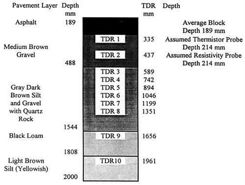
The pavement layer structure and location of the TDR probes are shown in Figure 1, which was obtained from the SMP Instrumentation Installation Report prepared for this site.
SMP Instrumentation Measurements
Unlike many of the other supplemental data collection to be performed during this exercise, the data collected from these measurements can and should be entered into the IMS. Just prior to beginning excavation of the materials at the instrumentation hole location, we recommend that the following SMP instrumentation measurements be performed:
These measurements should be possible since, except for the water table depth, they are all performed using the mobile data acquisition unit. Since this SMP site was previously deactivated, issues concerning air, rainfall and pavement gradient temperature measurements, measured by the instrumentation previously installed on-site are not considered an issue.
Materials Sampling at SMP Instrumentation
In order to obtain the material samples and perform material tests to provide supplemental data for the TDR measurements, an excavation will be required next to the instrumentation location located at station 5+21. There are two approaches to this excavation. The first approach would be to use a backhoe to excavate a small test pit adjacent to the instrumentation hole large enough for a person to stand in order to obtain material samples from around the TDR probes and perform measurements. The second approach utilizes an auger boring adjacent to the instrumentation.
During the excavation and sampling process, efforts should be made to remove some of the TDR and other SMP probes to examine them, note their general condition and take pictures. The intent of this procedure is to provide indications of the likely longevity of these types of probes and the likely corrosion mechanisms that affect their performance. Particular attention should be given to sensors, which have failed in order to discover why they failed.
Test Pit
Constructing a small test pit directly adjacent to the instrumentation hole, following the general LTPP procedures, is the preferred option. By carefully constructing a hole larger enough for a person to stand in, is the only way to attempt a measurement of the in-situ density and moisture content using a nuclear gauge at the approximate TDR depths as the hole is deepened. By performing in-situ density measurements with a nuclear gauge, material samples from the base and subbase layer for laboratory moisture content-density relations tests would not be needed. It also permits acquisition of a larger volume of material from the subgrade layers which include the relatively thin black loam layer in which TDR 9 is located and the light brown silt layer in which TDR 10 is positioned. It will also improve the ability to extract material samples from around the TDR probes for moisture content tests.
Some concerns over using a test pit excavation include increased pavement repair size, trench safety regulations, and equipment availability as compared to the auger boring option. However, due to the presence of rocks and cobbles in the subbase, the test pit option may require less time since the back hoe can remove the larger size material and afford easier access for hand removal of problem "large" rocks.
The field work associated with the test pit option would include the following general steps:
Since this test section is scheduled for overlay, the destructive nature of some of these procedures are not judged to be as critical as if the test section had to be put back into service with a surface patch for a long period of time.
Auger Boring
The auger option is less intrusive since a smaller volume of material is removed and thus requires less pavement repair material. However, it does not afford the ability to attempt in-situ density measurements, makes large rock and cobble removal more difficult, limits the amount of material that can be obtained from the subgrade, and increases the difficulty in obtaining "good" samples of materials from around the TDR probes. In spite of these difficulties, this method is considered viable.
For the auger option, the largest size auger available is desired. A 10" diameter, hollow stem auger was used to excavate the instrumentation hole. Of primary concern is the amount of material that can be obtained from the black loam subgrade layer. Obviously a smaller auger will produce less material. For LTPP standard testing, three auger borings were used to obtain adequate amounts of materials, however, in the general situation, the base layered tended to be the controlling factor in the need for three borings.
The field work associated with the auger option includes the following general steps:
Subgrade Material Characterization
It is proposed that the material characterization of the subgrade layers be performed on samples obtained only at the SMP instrumentation location. The standard LTPP practice is to obtain samples from each end of the test section. The concern over not sampling the section approach is the amount of time required to complete the excavation at the SMP instrumentation hole, and the difficulty imposed by the presence of rocks and cobbles in the subbase layer. If all of the field material sampling operations were to be performed within a single day, an additional drill rig might be required.
If the auger option is selected for the excavation at the instrumentation hole, then sample size is a concern for the black loam layer. One way to reduce the needed size of this sample is to omit the resilient modulus test. (We are not sure if Connecticut DOT has the necessary equipment to perform the LTPP P-46 test.) From the perspective of what is needed for SMP instrumentation interpretations, although preferred, the resilient modulus test of this relatively thin subsurface layer could be omitted.
The following are the standard battery of material characterization tests on GPS subgrade materials:
| Material Type, SHRP Test Designation, and Properties | Test Method | SHRP Protocol |
SS01. Sieve Analysis |
AASHTO T27-88I | P-51 |
SS02. Hydrometer to .001mm |
AASHTO T88-86 | P-42 |
SS03. Atterberg Limits |
AASHTO T89-87I T90-87I |
P-43 |
SS04. Classification/Type of Subgrade Soils |
AASHTO M145-82 ASTM D2488-84 |
P-52 |
SS05. Moisture-Density Relations |
AASHTO T99-86 T180-86 |
P-44 |
SS07. Resilient Modulus |
AASHTO 274-82 | P-46 |
SS09. Natural Moisture Content |
AASHTO T265-86 | P-49 |
Distress Mechanism Investigation
One of the ideas that have been discussed within the LTPP program for many years is the investigation of distress mechanisms. The concept is that after a test section has gone out of service, or is scheduled of rehabilitation, a "forensic" type of investigation should be performed to examine the details surrounding the causes and mechanisms of distress. Due to funding constraints, LTPP has not developed a formal program for these types of investigations.
To perform this type of investigation, we recommend that as a first step a site inspection be performed by LTPP and highway agency representatives. The purpose of this inspection is to note site specific distresses and likely causative factors. The result of this activity is an investigation plan. Some of the types of investigations and field tests that have been suggested for this type of work include:
While this approach is based on "what failed", equally important and more difficult to addressed is the investigation of "what worked" and why. Similar to diagnosing problems with a car from a manufacturer's viewpoint, knowing what worked requires understanding of what didn't work. Hence, in the case of superior performing pavements, it may be deemed prudent to conduct addition exploratory tests to discover an unknown factor.
Thickness Variation
If a test section is scheduled to go out of service, that is, no longer be monitored as part of the LTPP program, then measurements of the variation in the thickness of the bound surface layers is important. The concept is to obtain cores at the FWD test points within the test section. This reduces coring costs and provides significant information that can be used to improve the results from the backcalculation of FWD basin tests (i.e. non load transfer, corner, and edge tests on rigid pavements) and to quantify construction variability. First priority is to obtain thicknesses in the wheel path locations. Second priority is at the middle lane, basin test locations.
It is our present understanding that this site is proposed for monitoring continuation after rehabilitation. If the site is accepted for monitoring continuation, then this type of destructive sampling within the test section should not be performed. An on-site inspection maybe useful in evaluating the impact of the pipeline buried, in circa 1997, along the edge of the shoulder on the performance of this section. It is also noted that the agency has collected significant WIM traffic data on this site and has committed to reinstall the WIM scale after rehabilitation.
| << Previous | Main | Next >> |

