U.S. Department of Transportation
Federal Highway Administration
1200 New Jersey Avenue, SE
Washington, DC 20590
202-366-4000
Federal Highway Administration Research and Technology
Coordinating, Developing, and Delivering Highway Transportation Innovations
 |
| This report is an archived publication and may contain dated technical, contact, and link information |
|
Publication Number: FHWA-RD-03-031 Date: JUNE 2003 |
This section covers asphalt concrete-surfaced pavements (ACP), including ACP overlays on either asphalt concrete (AC) or portland cement concrete (PCC) pavements.
Each of the distresses has been grouped into one of the following categories:
Table 1 summarizes the various types of distress and unit of measurement. Some distresses also have defined severity levels.
|
DISTRESS TYPE
|
UNIT OF MEASURE
|
DEFINED SEVERITY LEVELS?
|
|
|---|---|---|---|
| A. | |||
| 1. Fatigue Cracking Square | Square Meters | Yes | |
| 2. Block Cracking Square | Square Meters | Yes | |
| 3. Edge Cracking | Meters | Yes | |
| 4a. Wheel Path Longitudinal Cracking | Meters | Yes | |
| 4b. Non-Wheel Path Longitudinal Cracking | Meters | Yes | |
| 5. Reflection Cracking at Joints Transverse Reflection Cracking Longitudinal Reflection Cracking |
Not Measured Not Measured |
N/A N/A |
|
| 6. Transverse Cracking | Number, Meters | Yes | |
|
B. |
|||
| 7. Patch/Patch Deterioration | Number, Square Meters | Yes | |
| 8. Potholes | Number, Square Meters | Yes | |
| C. | |||
| 9. Rutting | Millimeters | No | |
| 10. Shoving | Number, Square Meters | No | |
| D. | |||
| 11. Bleeding Square | Square Meters | No | |
| 12. Polished Aggregate | Square Meters | No | |
| 13. Raveling Square | Square Meters | No | |
| E. | |||
| 14. Lane-to-Shoulder Dropoff | Not Measured | N/A | |
| 15. Water Bleeding and Pumping | Number, Meters | No | |
This section includes the following distresses:
1.
Fatigue Cracking
2.
Block Cracking
3.
Edge Cracking
4a.
Longitudinal Cracking - Wheel Path
4b.
Longitudinal Cracking - Non-Wheel Path
5.
Reflection Cracking at Joints
6.
Transverse Cracking
Measurement of crack width is illustrated in Figure 1. Figure 2 depicts the effect on severity level of a crack, in this case block cracking, due to associated random cracking.
FIGURE 1
Measuring Crack Width in Asphalt Concrete-Surfaced Pavements
FIGURE 2
Effect on Severity Level of Block Cracking due to Associated
Random Cracking
Description
Occurs in areas subjected to repeated traffic loadings (wheel paths). Can be a series of interconnected cracks in early stages of development. Develops into many-sided, sharp-angled pieces, usually less than 0.3 meters (m) on the longest side, characteristically with a chicken wire/alligator pattern, in later stages.
Must have a quantifiable area.
Severity Levels
LOW
An area of cracks with no or only a few connecting cracks; cracks
are not spalled or sealed; pumping is not evident.
MODERATE
An area of interconnected cracks forming a complete pattern;
cracks may be slightly spalled; cracks may be sealed; pumping is not evident.
HIGH
An area of moderately or severely spalled interconnected cracks
forming a complete pattern; pieces may move when subjected to traffic;
cracks may be sealed; pumping may be evident.
How to Measure
Record square meters of affected area at each severity level. If different severity levels existing within an area cannot be distinguished, rate the entire area at the highest severity present.
FIGURE 3
Distress Type ACP 1 - Fatigue Cracking
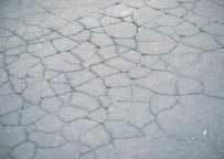
FIGURE 4 Distress Type ACP 1 - Chicken Wire/Alligator Pattern Cracking Typical in Fatigue Cracking |
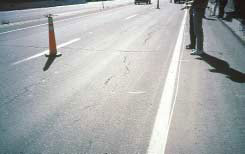
FIGURE 5 Distress Type ACP 1 - Low Severity Fatigue Cracking |
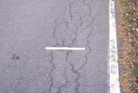
FIGURE 6 Distress Type ACP 1 - Moderate Severity Fatigue Cracking |
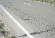
FIGURE 7 Distress Type ACP 1 - High Severity Fatigue Cracking with Spalled Interconnected Cracks |
Description
A pattern of cracks that divides the pavement into approximately rectangular pieces. Rectangular blocks range in size from approximately 0.1 m2 to 10 m2.
Severity Levels
LOW
Cracks with a mean width £ 6 millimeters (mm); or sealed cracks
with sealant material in good condition and with a width that cannot be
determined.
MODERATE
Cracks with a mean width > 6 mm and £ 19
mm; or any crack with a mean width £ 19 mm and
adjacent low severity random cracking.
HIGH
Cracks with a mean width > 19 mm; or any crack with a mean
width £ 19 mm and adjacent moderate to high severity random cracking.
How to Measure
Record square meters of affected area at each severity level. If fatigue cracking exists within the block cracking area, the area of block cracking is reduced by the area of fatigue cracking.
Note: An occurrence should be at least 15 m long before rating as block cracking.
FIGURE 8
Distress Type ACP 2 - Block Cracking
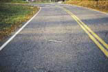
FIGURE 9
Distress Type ACP 2 - Block Cracking with Fatigue Cracking in the Wheel Paths
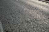
FIGURE 10
Distress Type ACP 2 - High Severity Block Cracking
Description
Applies only to pavements with unpaved shoulders. Crescent-shaped cracks or fairly continuous cracks which intersect the pavement edge and are located within 0.6 m of the pavement edge, adjacent to the shoulder. Includes longitudinal cracks outside of the wheel path and within 0.6 m of the pavement edge.
Severity Levels
LOW
Cracks with no breakup or loss of material.
MODERATE
Cracks with some breakup and loss of material for up to 10 percent
of the length of the affected portion of the pavement.
HIGH
Cracks with considerable breakup and loss of material for more
than 10 percent of the length of the affected portion of the pavement.
How to Measure
Record length in meters of pavement edge affected at each severity level. The combined quantity of edge cracking cannot exceed the length of the section.
Description
Cracks predominantly parallel to pavement centerline. Location within the lane (wheel path versus non-wheel path) is significant.
Severity levels
LOW
A crack with a mean width £6 mm; or a sealed crack with sealant
material in good condition and with a width that cannot be determined.
MODERATE
Any crack with a mean width > 6 mm and £ 19 mm; or any
crack with a mean width £ 19 mm and adjacent low severity random cracking.
HIGH
Any crack with a mean width > 19 mm; or any crack with a mean
width £ 19 mm and adjacent moderate to high severity random cracking.
FIGURE 13
Distress Type ACP 4 - Longitudinal Cracking
Record separately:
4A. WHEEL PATH LONGITUDINAL CRACKING
Record the length in meters of longitudinal cracking within the defined wheel paths at each severity level.
Record the length in meters of longitudinal cracking with sealant in good condition at each severity level.
Note: Any wheel path longitudinal crack that has associated random cracking is rated as fatigue cracking. Any wheel path longitudinal crack that meanders and has a quantifiable area is rated as fatigue cracking.
4B. NON-WHEEL PATH LONGITUDINAL CRACKING
Record the length in meters of longitudinal cracking not located in the defined wheel paths at each severity level.
Record the length in meters of longitudinal cracking with sealant in good condition at each severity level.
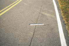
FIGURE 14
Distress Type ACP 4a - Moderate Severity Longitudinal Cracking in the Wheel Path
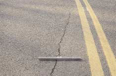
FIGURE 15
Distress Type ACP 4b - High Severity Longitudinal Cracking not in the Wheel Path
Description
Cracks in asphalt concrete overlay surfaces that occur over joints in concrete pavements.
Note: The slab dimensions beneath the AC surface must be known to identify reflection cracks at joints.
Severity Levels
LOW
An unsealed crack with a mean width £ 6 mm; or a sealed crack with
sealant
material in good condition and with a width that cannot be
determined.
MODERATE
Any crack with a mean width > 6 mm and £ 19 mm; or any
crack with a mean width £ 19 mm and adjacent low severity random cracking.
HIGH
Any crack with a mean width > 19 mm; or any crack with a mean
width £ 19 mm and adjacent moderate to high severity random cracking.
FIGURE 16
Distress Type ACP 5 - Reflection Cracking at Joints
How to Measure
Recorded as longitudinal cracking (ACP4) or transverse cracking (ACP6) on LTPP surveys.
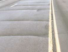
FIGURE 17
Distress Type ACP 5 - High Severity Reflection Cracking at Joints
Description
Cracks that are predominantly perpendicular to pavement centerline.
Severity Levels
LOW
An unsealed crack with a mean width £ 6 mm; or a sealed crack with
sealant material in good condition and with a width that cannot be
determined.
MODERATE
Any crack with a mean width > 6 mm and £ 19 mm; or any
crack with a mean width £ 19 mm and adjacent low severity random cracking.
HIGH
Any crack with a mean width > 19 mm; or any crack with a mean
width £ 19 mm and adjacent moderate to high severity random cracking.

FIGURE 18
Distress Type ACP 6 - Transverse Cracking Asphalt Concrete Surfaces
How to Measure
Record number and length of transverse cracks at each severity level. Rate the entire transverse crack at the highest severity level present for at least 10 percent of the total length of the crack. Length recorded, in meters, is the total length of the crack and is assigned to the highest severity level present for at least 10 percent of the total length of the crack.
Also record length in meters of transverse cracks with sealant in good condition at each severity level.
Note: The length recorded is the total length of the well-sealed crack and is assigned to the severity level of the crack. Record only when the sealant is in good condition for at least 90 percent of the length of the crack.
If the transverse crack extends through an area of fatigue cracking, the length of the crack within the fatigue area is not counted. The crack is treated as a single transverse crack, but at a reduced length.
Cracks less than 0.3 m in length are not recorded.
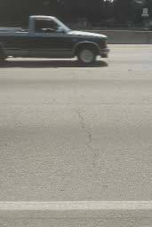
FIGURE 19
Distress Type ACP 6 - Low Severity Transverse Cracking
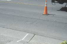
FIGURE 20
Distress Type ACP 6 - Moderate Severity Transverse Cracking
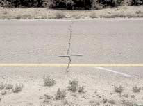
FIGURE 21
Distress Type ACP 6 - High Severity Transverse Cracking
This section includes the following distresses:
7.
Patch/Patch Deterioration
8.
Potholes
Description
Portion of pavement surface, greater than 0.1 m2, that has been removed and replaced or additional material applied to the pavement after original construction.
Severity Levels
LOW
Patch has, at most, low severity distress of any type including
rutting < 6 mm; pumping is not evident.
MODERATE
Patch has moderate severity distress of any type or rutting from 6
mm to 12 mm; pumping is not evident.
HIGH
Patch has high severity distress of any type including rutting
> 12 mm, or the patch has additional different patch material within it; pumping
may be evident.
How to Measure
Record number of patches and square meters of affected surface area at each severity level.
Note: Any distress in the boundary of the patch is included in rating the patch. Rutting (settlement) may be at the perimeter or interior of the patch.
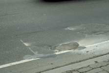
FIGURE 22
Distress Type ACP 7 - Patch/Patch Deterioration
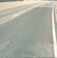
FIGURE 23
Distress Type ACP 7 - Low Severity Patch
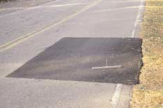
FIGURE 24
Distress Type ACP 7 - Moderate Severity Patch
Description
Bowl-shaped holes of various sizes in the pavement surface. Minimum plan dimension is 150 mm.
Severity Levels
LOW
< 25 mm deep.
MODERATE
25 mm to 50 mm deep.
HIGH
> 50 mm deep.
How to Measure
Record number of potholes and square meters of affected area at each severity level. Pothole depth is the maximum depth below pavement surface. If pothole occurs within an area of fatigue cracking the area of fatigue cracking is reduced by the area of the pothole.
FIGURE 26
Distress Type ACP 8 - Potholes
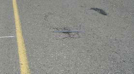
FIGURE 27
Distress Type ACP 8 - Low Severity Pothole
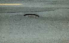
FIGURE 28
Distress Type ACP 8 - Moderate Severity Pothole
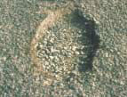
FIGURE 29
Distress Type ACP 8 - Moderate Severity Pothole, Close-up View
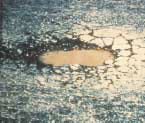
FIGURE 30
Distress Type ACP 8 - High Severity Pothole, Close-up View
This section includes the following types of surface deformations:
Description
A rut is a longitudinal surface depression in the wheel path. It may have associated transverse displacement.
Severity Levels
Not applicable. Severity levels could be defined by categorizing the measurements taken. A record of the measurements taken is much more desirable, because it is more accurate and repeatable than are severity levels.
How to Measure
Specific Pavement Studies (SPS)-3 ONLY. Record maximum rut depth to the nearest millimeter, at 15.25-m intervals for each wheel path, as measured with a 1.2-m straight edge.
All other LTPP sections: Transverse profile is measured with a Dipstick® profiler at 15.25-m intervals.
FIGURE 31
Distress Type ACP 9 - Rutting
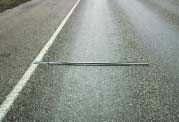
FIGURE 32
Distress Type ACP 9 - Rutting
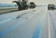
FIGURE 33
Distress Type ACP 9 - Standing Water in Ruts
Description
Shoving is a longitudinal displacement of a localized area of the pavement surface. It is generally caused by braking or accelerating vehicles, and is usually located on hills or curves, or at intersections. It also may have associated vertical displacement.
Severity Levels
Not applicable. However, severity levels can be defined by the relative effect of shoving on ride quality.
How to Measure
Record number of occurrences and square meters of affected surface area.
FIGURE 34
Distress Type ACP 10 - Shoving
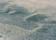
FIGURE 35
Distress Type ACP 10 - Shoving in Pavement Surface
This section includes the following types of surface defects:
11.
Bleeding
12.
Polished Aggregate
13.
Raveling
Description
Excess bituminous binder occurring on the pavement surface, usually found in the wheel paths. May range from a surface discolored relative to the remainder of the pavement, to a surface that is losing surface texture because of excess asphalt, to a condition where the aggregate may be obscured by excess asphalt possibly with a shiny, glass-like, reflective surface that may be tacky to the touch.
Severity Levels
Not applicable. The presence of bleeding indicates potential mixture related performance problems. Extent is sufficient to monitor any progression.
How to Measure
Record square meters of surface area affected.
Note: Preventative maintenance treatments (slurry seals, chip seals, fog seals, etc.) sometimes exhibit bleeding characteristics. These occurrences should be noted, but not rated as bleeding.

FIGURE 36
Distress Type ACP 11 - Discoloration
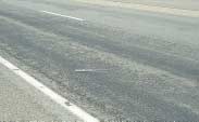
FIGURE 37
Distress Type ACP 11 - Loss of Texture
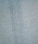
FIGURE 38
Distress Type ACP 11 -
Aggregate Obscured
Description
Surface binder worn away to expose coarse aggregate.
Severity Levels
Not applicable. However, the degree of polishing may be reflected in a reduction of surface friction.
How to Measure
Record square meters of affected surface area. Polished aggregate should not be rated on test sections that have received a preventive maintenance treatment that has covered the original pavement surface.
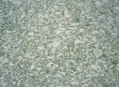
Description
Wearing away of the pavement surface caused by the dislodging of aggregate particles and loss of asphalt binder. Raveling ranges from loss of fines to loss of some coarse aggregate and ultimately to a very rough and pitted surface with obvious loss of aggregate.
Severity Levels
Not applicable. The presence of raveling indicates potential mixture related performance problems. Extent is sufficient to monitor any progression.
How to Measure
Record square meters of affected surface. Raveling should not be rated on chip seals.
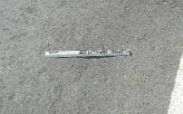
FIGURE 40
Distress Type ACP 13 - Loss of Fine Aggregate
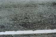
FIGURE 41
Distress Type ACP 13 - Loss of Fine and Some Coarse Aggregate

FIGURE 42
Distress Type ACP 13 - Loss of Coarse Aggregate
This section includes the following distresses:
14.
Lane-to-Shoulder Dropoff
15.
Water Bleeding and Pumping
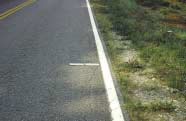
Description
Difference in elevation between the traveled surface and the outside shoulder. Typically occurs when the outside shoulder settles as a result of pavement layer material differences.
Severity Level
Not applicable. Severity levels could be defined by categorizing the measurements taken. A record of the measurements taken is much more desirable, however, because it is more accurate and repeatable than are severity levels.
How to Measure
FIGURE 43
Distress Type ACP 14 - Lane-to-Shoulder Dropoff
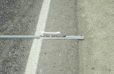
FIGURE 44
Distress Type ACP 14 - Lane-to-Shoulder Dropoff
Description
Seeping or ejection of water from beneath the pavement through cracks. In some cases, detectable by deposits of fine material left on the pavement surface, which were eroded (pumped) from the support layers and have stained the surface.
Severity Levels
Not applicable. Severity levels are not used because the amount and degree of water bleeding and pumping changes with varying moisture conditions.
How to Measure
Record the number of occurrences of water bleeding and pumping and the length in meters of affected pavement with a minimum length of 1 m.
Note. The combined length of water bleeding and pumping cannot exceed the length of the test section.
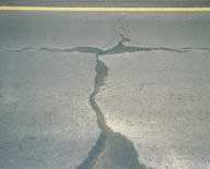
FIGURE 45
Distress Type ACP 15 - Water Bleeding and Pumping
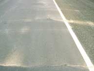
FIGURE 46
Distress Type ACP 15 - Fine Material Left on Surface by Water Bleeding
and Pumping