U.S. Department of Transportation
Federal Highway Administration
1200 New Jersey Avenue, SE
Washington, DC 20590
202-366-4000
Federal Highway Administration Research and Technology
Coordinating, Developing, and Delivering Highway Transportation Innovations
 |
| This report is an archived publication and may contain dated technical, contact, and link information |
|
Publication Number: FHWA-RD-03-031 Date: JUNE 2003 |
This section covers jointed (plain and reinforced) portland cement concrete-surfaced pavements (JCP), including jointed concrete overlays on PCC pavements.
Each of the distresses has been grouped into one of the following categories:
Table 2 summarizes the various types of distress and unit of measurement. Some distresses also have defined severity levels.
TABLE 2. Jointed Concrete-Surfaced Pavement Distress Types
| DISTRESS TYPE | UNIT OF MEASURE | DEFINED SEVERITY LEVELS? | |
|---|---|---|---|
|
A. Cracking |
|||
|
1. Corner Breaks |
Number | Yes | |
|
2. Durability Cracking ("D" Cracking) |
Number of Slabs, Square Meters | Yes | |
|
3. Longitudinal Cracking |
Meters | Yes | |
|
4. Transverse Cracking Number |
Meters | Yes | |
|
5a. Transverse Joint Seal Damage |
Number | Yes | |
|
5b. Longitudinal Joint Seal Damage |
Number, Meters | No | |
|
6. Spalling of Longitudinal Joints |
Meters | Yes | |
|
7. Spalling of Transverse Joints |
Number, Meters | Yes | |
|
8a. Map Cracking |
Number, Square Meters | No | |
|
8b. Scaling |
Number, Square Meters | No | |
|
9. Polished Aggregate Square |
Square Meters | No | |
|
10. Popouts |
Not Measured | N/A | |
|
11. Blowups |
Number | No | |
|
12. Faulting of Transverse Joints and Cracks |
Millimeters | No | |
|
13. Lane-to-Shoulder Dropoff |
Millimeters | No | |
|
14. Lane-to-Shoulder Separation |
Millimeters | No | |
|
15. Patch/Patch Deterioration |
Number, Square Meters | Yes | |
|
16. Water Bleeding and Pumping |
Number, Meters | No | |
This section includes the following types of distresses:
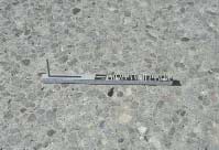
Figure 47 illustrates the proper measurement of crack width and width of spalling for cracks and joints.
FIGURE 47
Measuring Widths of Spalls and Cracks in Jointed Concrete Pavement
Description
A portion of the slab separated by a crack, which intersects the adjacent transverse and longitudinal joints, describing approximately a 45-degree angle with the direction of traffic. The length of the sides is from 0.3 m to one-half the width of the slab on each side of the corner.
Severity Levels
LOW
Crack is not spalled for more than 10 percent of the length of the
crack; there is no measurable faulting; and the corner piece is not broken into
two or more pieces and has no loss of material and no patching.
MODERATE
Crack is spalled at low severity for more than 10 percent of its
total length; or faulting of crack or joint is < 13 mm; and the corner piece is
not broken into two or more pieces.
HIGH
Crack is spalled at moderate to high severity for more than 10
percent of its total length; or faulting of the crack or joint is ≥ 13 mm; or the
corner piece is SYMBOL
broken into two or more pieces or contains patch material.
How to Measure
Record number of corner breaks at each severity level. Corner breaks that have been repaired by completely removing all broken pieces and replacing them with patching material (rigid or flexible) should be rated as a patch. If the boundaries of the corner break are visible, then also rate as a high severity corner break. Note: This does not affect the way patches are rated. All patches meeting the size criteria are rated.

FIGURE 48
Distress Type JCP 1—Corner Breaks
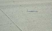
FIGURE 49
Distress Type JCP 1—Low Severity Corner Break
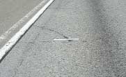
FIGURE 50
Distress Type JCP 1—Moderate Severity Corner Break
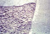
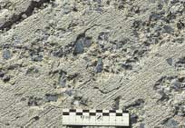
Description
Closely spaced crescent-shaped hairline cracking pattern.
Occurs adjacent to joints, cracks, or free edges; initiating in slab corners. Dark coloring of the cracking pattern and surrounding area.
How to Measure
Record number of slabs with "D" cracking and square meters of area affected at each severity level. The slab and affected area severity rating is based on the highest severity level present for at least 10 percent of the area affected.
Severity Levels
LOW
"D" cracks are tight, with no loose or missing pieces, and no
patching is in the affected area.
MODERATE
"D" cracks are well-defined, and some small pieces are loose or
have been displaced.
HIGH
"D" cracking has a well-developed pattern, with a significant
amount of loose or missing material. Displaced pieces, up to 0.1 m2, may have been
patched.
FIGURE 51
Distress Type JCP 2—Durability Cracking ("D" Cracking)
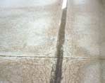
FIGURE 52
Distress Type JCP 2—Moderate Severity "D" Cracking with Well-Defined Pattern
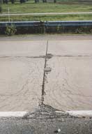
FIGURE 53
Distress Type JCP 2—High Severity "D" Cracking with Loose and Missing Material
Description
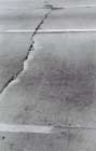
Cracks that are predominantly parallel to the pavement centerline.
Severity Levels
LOW
Crack widths < 3 mm, no spalling and no measurable faulting; or
well-sealed and with a width that cannot be determined.
MODERATE
Crack widths ³ 3 mm and < 13 mm; or with spalling < 75 mm;
or faulting up to 13 mm.
HIGH
Crack widths ³ 13 mm; or with spalling ³ 75 mm; or
faulting ³ 13
mm.
FIGURE 54
Distress Type JCP 3—Longitudinal Cracking
How to Measure
Record length in meters of longitudinal cracking at each severity level. Also record length in meters of longitudinal cracking with sealant in good condition at each severity level.
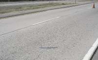
FIGURE 55
Distress Type JCP 3—Low Severity Longitudinal Cracking
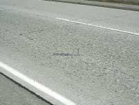
FIGURE 56
Distress Type JCP 3—Moderate Severity Longitudinal Cracking
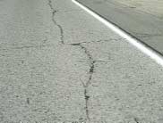
FIGURE 57
Distress Type JCP 3—High Severity Longitudinal Cracking
Description
Cracks that are predominantly perpendicular to the pavement centerline.
Severity Levels
LOW
Crack widths < 3 mm, no spalling and no measurable faulting; or
well-sealed and the width cannot be determined.
MODERATE
Crack widths ³ 3 mm and < 6 mm; or with spalling < 75 mm; or
faulting up to 6 mm.
HIGH
Crack widths ³ 6 mm; or with spalling ³ 75 mm; or
faulting ³ 6
mm.
FIGURE 58
Distress Type JCP 4—Transverse Cracking
How to Measure
Record number and length of transverse cracks at each severity level. Rate the entire transverse crack at the highest severity level present for at least 10 percent of the total length of the crack. Length recorded, in meters, is the total length of the crack and is assigned to the highest severity level present for at least 10 percent of the total length of the crack.
Also record the length, in meters, of transverse cracking at each severity level with sealant in good condition. The length recorded, in meters, is the total length of the well-sealed crack and is assigned to the severity level of the crack. Record only when the sealant is in good condition for at least 90 percent of the length of the crack.
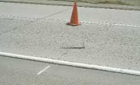
FIGURE 59
Distress Type JCP 4—Moderate Severity Transverse Cracking
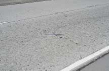
FIGURE 60
Distress Type JCP 4—High Severity Transverse Cracking
This section includes the following types of distresses:
5a. Transverse Joint Seal Damage
5b. Longitudinal Joint Seal Damage
6. Spalling of Longitudinal Joints
7. Spalling of Transverse Joints
Description
Joint seal damage is any condition which enables incompressible materials or water to infiltrate the joint from the surface. Typical types of joint seal damage are:
Severity Levels
LOW
Joint seal damage as described above exists over less than 10 percent of the joint.
MODERATE
Joint seal damage as described above exists over 10-50 percent of the joint.
HIGH
Joint seal damage as described above exists over more than 50 percent of the joint.
How to Measure
Indicate whether the transverse joints have been sealed (yes or no). If yes, record number of sealed transverse joints at each severity level. Any joint seal with no apparent damage is considered to be low severity.
Severity Levels
None.
How to Measure
Record number of longitudinal joints that are sealed (0, 1, 2). Record total length of sealed longitudinal joints with joint seal damage as described above. Individual occurrences are recorded only when at least 1 m in length.
JOINTED PORTLAND CEMENT CONCRETE SURFACES
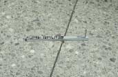
FIGURE 61
Distress Type JCP 5—Low Severity Joint Seal Damage
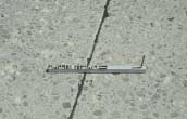
FIGURE 62
Distress Type JCP 5—Moderate Severity Joint Seal Damage
Description
Cracking, breaking, chipping, or fraying of slab edges within 0.3 m from the face of the longitudinal joint.
Severity Levels
LOW
Spalls < 75 mm wide, measured to the face of the joint, with
loss of material, or spalls with no loss of material and no patching.
MODERATE
Spalls 75 mm to 150 mm wide, measured to the face of the joint, with loss of material.
HIGH
Spalls > 150 mm wide, measured to the face of the joint, with loss of material or is broken into two or more pieces or contains patch material.
How to Measure
Record length in meters of longitudinal joint affected at each severity level. Only record spalls that have a length of 0.1 m or more. Spalls that have been repaired by completely removing all broken pieces and replacing them with patching material (rigid or flexible) should be rated as a patch. If the boundaries of the spall are visible, then also rate as a high severity spall. Note: All patches meeting size criteria are rated as patches.
Joint Deficiencies
FIGURE 63
Distress Type JCP 6—Spalling of Longitudinal Joints
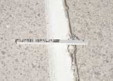
FIGURE 64
Distress Type JCP 6—Low Severity Spalling of Longitudinal Joint
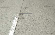
FIGURE 65
Distress Type JCP 6—High Severity Spalling of Longitudinal Joint
Description
Cracking, breaking, chipping, or fraying of slab edges within 0.3 m from the face of the transverse joint.
Severity Levels
LOW
Spalls < 75 mm wide, measured to the face of the joint, with loss of material, or spalls with no loss of material and no patching.
MODERATE
Spalls 75 mm to 150 mm wide, measured to the face of the joint, with loss of material.
HIGH
Spalls > 150 mm wide, measured to the face of the joint, with loss of material, or broken into two or more pieces, or contains patch
material.
How to Measure
Record number of affected transverse joints at each severity level. A joint is affected only if the total length of spalling is 10 percent or more of the length of the joint. Rate the entire transverse joint at the highest severity level present for at least 10 percent of the total length of the spalling. Record length in meters of the spalled portion of the joint at the assigned severity level for the joint. Spalls that have been repaired by completely removing all broken pieces and replacing them with patching material (rigid or flexible) should be rated as a patch. If the boundaries of the spall are visible, then also rate as a high severity spall. Note: All patches meeting size criteria are rated as patches.
FIGURE 66
Distress Type JCP 7—Spalling of Transverse Joints
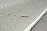
FIGURE 67
Distress Type JCP 7—Moderate Severity Spalling of Transverse Joint, Far View
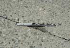
FIGURE 68
Distress Type JCP 7—Moderate Severity Spalling of Transverse Joint, Close-up View
This section includes the following types of distresses:
8a. Map Cracking
8b. Scaling
9. Polished Aggregate
10. Popouts
Description
A series of cracks that extend only into the upper surface of the slab. Larger cracks frequently are oriented in the longitudinal direction of the pavement and are interconnected by finer transverse or random cracks.
Severity Levels
Not applicable.
How to Measure
Record the number of occurrences and the square meters of affected area.
Description
Scaling is the deterioration of the upper concrete slab surface, normally 3 mm to 13 mm, and may occur anywhere over the pavement.
Severity Levels
Not applicable.
How to Measure
Record the number of occurrences and the square meters of affected area.
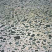
Description
Surface mortar and texturing worn away to expose coarse aggregate.
Severity Levels
Not applicable. However, the degree of polishing may be reflected in a reduction of surface friction.
How to Measure
Record square meters of affected surface area.
NOTE: Diamond grinding also removes the surface mortar and texturing. However, this condition should not be recorded as polished aggregate, but instead, be noted by a comment.
Description
Small pieces of pavement broken loose from the surface, normally ranging in diameter from 25 mm to 100 mm, and depth from 13 mm to 50 mm.
Severity Levels
Not applicable. However, severity levels can be defined in relation to the intensity of popouts as measured below.
How to Measure
This section includes the following distresses:
11. Blowups
12. Faulting of Transverse Joints and Cracks
13. Lane-to-Shoulder Dropoff
14. Lane-to-Shoulder Separation
15. Patch/Patch Deterioration
16. Water Bleeding and Pumping
Description
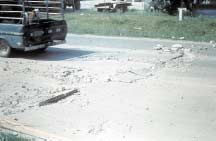
Localized upward movement of the pavement surface at transverse joints or cracks, often accompanied by shattering of the concrete in that area.
Severity Levels
Not applicable. However, severity levels can be defined by the relative effect of a blowup on ride quality and safety.
How to Measure
Description
Difference in elevation across a joint or crack.
Severity Level
Not applicable. Severity levels could be defined by categorizing the measurements taken. A complete record of the measurements taken is much more desirable, however, because it is more accurate and repeatable than are severity levels.
How to Measure
Record in millimeters, to the nearest millimeter: 0.3 m and 0.75 m from the outside slab edge (approximately the outer wheel path). For a widened lane, the wheel path location will be 0.75 m from the outside lane edge stripe. At each location, three measurements are made, but only the approximate average of the readings is recorded.
If the "approach" slab is higher than the "departure" slab, record faulting as positive (+); if the approach slab is lower, record faulting as negative (-).
Faulting on PCC pavements is to be measured using a FHWA-modified Georgia Faultmeter. A representative reading from three distinct measurements at each location is to be used and recorded on sheet 6.
When anomalies such as patching, spalling, and corner breaks are encountered, the faultmeter should be offset to avoid the anomaly. The maximum offset is 0.3 m. A null value ("N") should be recorded and entered into the database when the surveyor is unable to take a measurement due to an anomaly.
Surveyors must ensure that they have a working faultmeter with fully charged batteries prior to beginning a survey on a jointed PCC test section. Complete faulting measurements and survey sheet 6 at the beginning of the distress survey to ensure that this data is collected.
Point distance measurements entered on sheet 6 for joints and transverse cracks should be consistent between surveys of the same test section to an accuracy of less than 0.5 m. Evaluate newly observed distresses and point distance differences for previously identified distresses of 0.5 m and greater with a metric tape measure. Note: The precise start point of surveys must be clearly identified in the field.
FIGURE 77
Distress Type JCP 12—Faulting of Transverse Joints and Cracks
Description
Difference in elevation between the edge of slab and outside shoulder; typically occurs when the outside shoulder settles.
Severity Levels
Not applicable. Severity levels can be defined by categorizing the measurements taken. A complete record of the measurements taken is much more desirable, however, because it is more accurate and repeatable than are severity levels.
How to Measure
Measure at the longitudinal construction joint between the lane edge and the shoulder.
Record to the nearest millimeter at 15.25-m intervals along the lane-to-shoulder joint.
If the traveled surface is lower than the shoulder, record as a negative (-) value.
FIGURE 79
Distress Type JCP 13—Lane-to-Shoulder Dropoff
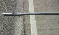
FIGURE 80
Distress Type JCP 13—Lane-to-Shoulder Dropoff
Description
Widening of the joint between the edge of the slab and the shoulder.
Severity Levels
Not applicable. Severity levels can be defined by categorizing the measurements taken. A complete record of the measurements taken is much more desirable, however, because it is more accurate and repeatable than severity levels.
How to Measure
Record to the nearest millimeter at intervals of 15.25 m along the lane-to-shoulder joint. Indicate whether the joint is well-sealed (yes or no) at each location.
Note: A null value ("N") should be recorded and entered into the database when the surveyor is unable to take a measurement due to an anomaly such as sealant or patch material.
FIGURE 81
Distress Type JCP 14—Lane-to-Shoulder Separation
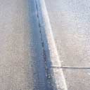
FIGURE 82
Distress Type JCP 14—Poorly Sealed Lane-to-Shoulder Separation
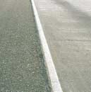
FIGURE 83
Distress Type JCP 14—Well-Sealed Lane-to-Shoulder Separation
Description
A portion, greater than 0.1 m2, or all of the original concrete slab that has been removed and replaced, or additional material applied to the pavement after original construction.
Severity Levels
LOW
Patch has low severity distress of any type; and no measurable
faulting or settlement; pumping is not evident.
MODERATE
Patch has moderate severity distress of any type; or faulting or
settlement up to 6 mm; pumping is not evident.
HIGH
Patch has a high severity distress of any type; or faulting or
settlement ³ 6
mm;pumping may be evident.
FIGURE 84
Distress Type JCP 15—Patch/Patch Deterioration
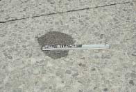
FIGURE 85
Distress Type JCP 15—Small, Low Severity Asphalt Concrete Patch
How to Measure
Record number of patches and square meters of affected surface area at each severity level, recorded separately by material type—rigid versus flexible. For slab replacement, rate each slab as a separate patch and continue to rate joints.
Note: All patches meeting size criteria are rated.
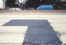
FIGURE 86
Distress Type JCP 15—Large, Low Severity Asphalt Concrete Patch
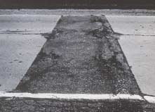
FIGURE 87
Distress Type JCP 15—Large, High Severity Asphalt Concrete Patch
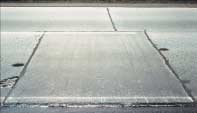
FIGURE 88
Distress Type JCP 15—Large, Low Severity Portland Cement Concrete Patch
Description
Seeping or ejection of water from beneath the pavement through cracks. In some cases, detectable by deposits of fine material left on the pavement surface, which were eroded (pumped) from the support layers and have stained the surface.
Severity Levels
Not applicable. Severity levels are not used because the amount and degree of water bleeding and pumping changes with varying moisture conditions.
How to Measure
Record the number of occurrences of water bleeding and pumping and the length in meters of affected pavement with a minimum length of 1 m.
Note. The combined length of water bleeding and pumping cannot exceed the length of the test section.
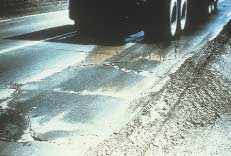
FIGURE 89
Distress Type JCP 16—Water Bleeding and Pumping