U.S. Department of Transportation
Federal Highway Administration
1200 New Jersey Avenue, SE
Washington, DC 20590
202-366-4000
Federal Highway Administration Research and Technology
Coordinating, Developing, and Delivering Highway Transportation Innovations
 |
| This report is an archived publication and may contain dated technical, contact, and link information |
|
Publication Number: FHWA-RD-03-031 Date: JUNE 2003 |
This section covers continuously reinforced concrete-surfaced pavements (CRCP), including continuously reinforced concrete overlays on PCC pavements. Each of the distresses has been grouped into one of the following categories:
Table 3 summarizes the various types of distress and unit of measurement. Some distresses also have defined severity levels.
TABLE 3. Continuously Reinforced Concrete-Surfaced Pavement Distress Types
| DISTRESS TYPE | UNIT OF MEASURE | DEFINED SEVERITY LEVELS? | |
|---|---|---|---|
| A. Cracking | |||
|
1. Durability Cracking ("D" Cracking)
|
Number, Square Meters | Yes | |
|
2. Longitudinal Cracking
|
Meters | Yes | |
|
3. Transverse Cracking
|
Number, Meters | Yes | |
| B. Surface Defects | |||
|
4a. Map Cracking
|
Number, Square Meters | No | |
|
4b. Scaling
|
Number, Square Meters | No | |
|
5. Polished Aggregate
|
Square Meters | No | |
|
6. Popouts
|
Not Measured | N/A | |
| C. Miscellaneous Distress | |||
|
7. Blowups
|
Number | No | |
|
8. Transverse Construction Joint Deterioration
|
Number | Yes | |
|
9. Lane-to-Shoulder Dropoff
|
Millimeters | No | |
|
10. Lane-to-Shoulder Separation
|
Millimeters | No | |
|
11. Patch/Patch Deterioration
|
Number, Square Meters | Yes | |
|
12. Punchouts
|
Number | Yes | |
|
13. Spalling of Longitudinal Joints
|
Meters | Yes | |
|
14. Water Bleeding and Pumping
|
Number, Meters | No | |
|
15. Longitudinal Joint Seal Damage
|
Number, Meters | No | |
This section includes the following distresses:
Description
Closely spaced, crescent-shaped hairline cracking pattern.
Occurs adjacent to joints, cracks, or free edges. Initiates at the intersection, e.g., cracks and a free edge.
Dark coloring of the cracking pattern and surrounding area.
Severity Levels
LOW
"D" cracks are tight, with no loose or missing pieces, and no patching is in the affected area.
MODERATE
"D" cracks are well defined, and some small pieces are loose or have been displaced.
HIGH
"D" cracking has a well-developed pattern, with a significant amount of loose or missing material.
Displaced pieces, up to 0.1 m2, may have been patched.
How to Measure
Record number of affected transverse cracks at each severity level
and the square meters of area affected at each severity level. The
transverse crack and affected area severity rating is based on the highest severity
level present for at least 10 percent of the area affected.
FIGURE 90
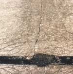
FIGURE 91
Distress Type CRCP 1—Moderate Severity "D" Cracking at Transverse Crack
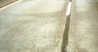
FIGURE 92
Distress Type CRCP 1—High Severity
"D" Cracking at Longitudinal Joint
Description
Cracks that are predominantly parallel to the pavement centerline.
Severity Levels
LOW
Crack widths < 3 mm, no spalling, and there is no measurable faulting; or
well sealed and with a width that cannot be determined.
MODERATE
Crack widths ³ 3 mm and < 13 mm; or with spalling < 75 mm;
or faulting up to 13 mm.
HIGH
Crack widths ³ 13 mm; or with spalling ³ 75 mm; or
faulting ³ 13
mm.
How to Measure
Record length in meters of longitudinal cracking at each severity level. Also record length in meters of longitudinal cracking with sealant in good condition at each severity level.
FIGURE 93
Distress Type CRCP 2—Longitudinal Cracking
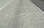
Figure 94
Distress Type CRCP 2—Low Severity Longitudinal Cracking
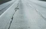
FIGURE 95
Distress Type CRCP 2—High Severity
Longitudinal Cracking
Description
Cracks that are predominantly perpendicular to the pavement centerline. This cracking is expected in a properly functioning CRCP. All transverse cracks that intersect an imaginary longitudinal line at midlane, and propagate from the pavement edges, shall be counted as individual cracks, as illustrated below.
Cracks that do not cross midlane are not counted.
Severity Levels
LOW
Cracks that are not spalled or with spalling along £ 10 percent of
the crack length.
MODERATE
Cracks with spalling along > 10 percent and £ 50 percent of
the crack length.
HIGH
Cracks with spalling along > 50 percent of the crack length.
FIGURE 96
Distress Type CRCP 3—Transverse
Cracking
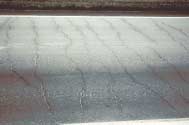
FIGURE 97
Distress Type CRCP 3—Transverse Cracking Pattern
How to Measure
Record separately the number and length in meters of transverse cracking at each severity level. The sum of all the individual crack lengths shall be recorded. Then record the total number of transverse cracks within the survey section.
Note: Cracks that do not cross midlane, although not counted, should be drawn on the map sheets.
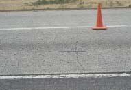
FIGURE 98
Distress Type CRCP 3—Low Severity Transverse Cracking
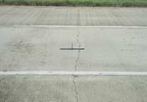
FIGURE 99
Distress Type CRCP 3—Moderate Severity Transverse Cracking
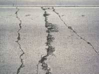
FIGURE 100
Distress Type CRCP 3—High Severity
Transverse Cracking
This section includes the following:
4a. Map Cracking
4b. Scaling
5. Polished Aggregate
6. Popouts
Description
A series of cracks that extend only into the upper surface of the slab. Larger cracks frequently are oriented in the longitudinal direction of the pavement and are interconnected by finer transverse or random cracks.
Severity Levels
Not applicable.
How to Measure
Record the number of occurrences and the square meters of affected area. When an entire section is affected with map cracking, it should be considered one occurrence.
Description
Scaling is the deterioration of the upper concrete slab surface, normally 3 mm to 13 mm, and may occur anywhere over the pavement.
Severity Levels
Not applicable.
How to Measure
Record the number of occurrences and the square meters of affected area.
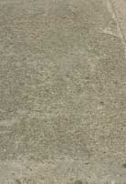
Description
Surface mortar and texturing worn away to expose coarse aggregate.
Severity Levels
Not applicable. However, the degree of polishing may be reflected in a reduction of surface friction.
How to Measure
Record square meters of affected surface area.
NOTE: Diamond grinding also removes the surface mortar and texturing. However, this condition should not be recorded as polished aggregate but instead should be noted by a comment.
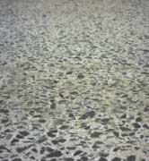
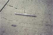
FIGURE 103
Distress Type CRCP 5—Polished Aggregate
Description
Small pieces of pavement broken loose from the surface, normally ranging in diameter from 25 mm to 100 mm and depth from 13 mm to 50 mm.
Severity Levels
Not applicable. However, severity levels can be defined in relation to the intensity of popouts as measured below.
How to Measure
FIGURE 104
Distress Type CRCP 6—Popouts
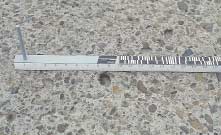
FIGURE 105
Distress Type CRCP 6—Popouts
This section includes the following distresses:
7. Blowups
8. Transverse Construction Joint Deterioration
9. Lane-to-Shoulder Dropoff
10. Lane-to-Shoulder Separation
11. Patch/Patch Deterioration
12. Punchouts
13. Spalling of Longitudinal Joints
14. Water Bleeding and Pumping
15. Longitudinal Joint Seal Damage
Description
Localized upward movement of the pavement surface at transverse joints or cracks, often accompanied by shattering of the concrete in that area.
Severity Levels
Not applicable.
However, severity levels can be defined by the relative effect of a blowup on ride quality and safety.
How to Measure
Record number of blowups.
FIGURE 106
Distress Type CRCP 7—Blowups
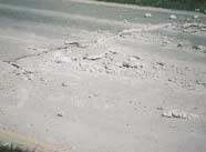
FIGURE 107
Distress Type CRCP 7—A Blowup
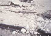
FIGURE 108
Distress Type CRCP 7—Close-up View of a Blowup
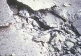
FIGURE 109
Distress Type CRCP 7—Exposed Steel in a Blowup
Description
Series of closely spaced transverse cracks or a large number of interconnecting cracks occurring near the construction joint.
Severity Levels
LOW
No spalling or faulting within 0.6 m of construction joint.
MODERATE
Spalling < 75 mm exists within 0.6 m of construction joint.
HIGH
Spalling ³ 75 mm and breakup exists within 0.6 m of construction joint.
How to Measure
Record number of construction joints at each severity level.
FIGURE 110
Distress Type CRCP 8—Transverse Construction Joint Deterioration
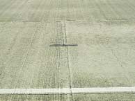
FIGURE 111
Distress Type CRCP 8—Low Severity
Transverse Construction Joint Deterioration
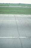
FIGURE 112
Distress Type CRCP 8—Moderate Severity Transverse Construction Joint Deterioration

FIGURE 113
Distress Type CRCP 8—
Low Severity Transverse Construction Joint
Deterioration
Description
Difference in elevation between the edge of slab and outside shoulder;typically occurs when the outside shoulder settles.
Severity Levels
Not applicable. Severity levels could be defined by categorizing the measurements taken. A complete record of the measurements taken is much more desirable, however, because it is more accurate and repeatable than are severity levels.
How to Measure
Measure at the longitudinal construction joint between the lane edge and the shoulder.
Record in millimeters to the nearest millimeter at 15.25-m intervals along the lane-to-shoulder joint.
If the traveled surface is lower than the shoulder, record as a negative (-) value.
FIGURE 114
Distress Type CRCP 9—Lane-to-Shoulder Dropoff
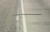
FIGURE 115
Distress Type CRCP 9—Lane-to-
Shoulder Dropoff
Description
Widening of the joint between the edge of the slab and the shoulder.
Severity Levels
Not applicable. Severity levels could be defined by categorizing the measurements taken. A complete record of the measurements taken is much more desirable, however, because it is more accurate and repeatable than are severity levels.
How to Measure
Record in millimeters to the nearest millimeter at intervals of 15.25 m along the lane-to-shoulder joint and indicate whether the joint is well-sealed (yes or no) at each location. Note: A null value ("N") should be recorded and entered into the database when the surveyor is unable to take a measurement due to an anomaly such as sealant or patch material.
Description
A portion, greater than 0.1 m2, or all of the original concrete slab that has been removed and replaced, or additional material applied to the pavement after original construction.
Severity Levels
LOW
Patch has, at most, low severity distress of any type; and no
measurable faulting or settlement; pumping is not evident.
MODERATE
Patch has moderate severity distress of any type; or faulting or
settlement up to 6 mm; pumping is not evident.
HIGH
Patch has a high severity distress of any type; or faulting or
settlement ³ 6 mm; pumping may be evident.
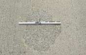
FIGURE 119
Distress Type CRCP 11—Small, Low
Severity Asphalt Concrete Patch
How to Measure
Record number of patches and square meters of affected surface area at each severity level, recorded separately by material type—rigid versus flexible.
Note: Panel replacement shall be rated as a patch. Any sawn joints shall be considered construction joints and rated separately. All patches are rated regardless of location.
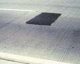
FIGURE 120
Distress Type CRCP 11—Low Severity
Asphalt Concrete Patch
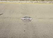
FIGURE 121
Distress Type CRCP 11—Moderate
Severity Asphalt Concrete Patch
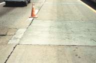
FIGURE 122
Distress Type CRCP 11—Low Severity
Portland Cement Concrete Patch
Description
The area enclosed by two closely spaced (usually < 0.6 m) transverse cracks, a short longitudinal crack, and the edge of the pavement or a longitudinal joint. Also includes "Y" cracks that exhibit spalling, breakup, or faulting.
Severity Levels
LOW
Longitudinal and transverse cracks are tight and may have spalling
< 75 mm or faulting < 6 mm with no loss of material and no patching. Does
not include "Y" cracks.
MODERATE
Spalling ³ 75 mm and < 150 mm or faulting ³ 6 mm and < 13 mm exists.
HIGH
Spalling ³ 150 mm, or concrete within the punchout is punched down by ³ 13 mm or is loose and moves under traffic or is broken into two or
more pieces or contains patch material.
How to Measure
Record number of punchouts at each severity level.
The cracks which outline the punchout are also recorded under "Longitudinal Cracking" (CRCP 2) and "Transverse Cracking" (CRCP 3).
Punchouts that have been repaired by completely removing all broken pieces and replacing them with patching material (rigid or flexible) should be rated as a patch. If the boundaries of the punchout are visible, then also rate as a high severity punchout.
Note: Areas between two transverse cracks spaced greater than 0.6 m but less than or equal to 1 m apart, and bounded by the edge of pavement (or longitudinal joint) and a longitudinal crack, are rated as punchouts if the cracks are exhibiting spalling, or the area is breaking up or faulting.
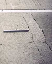
FIGURE 125
Distress Type CRCP 12—Moderate
Severity Punchout
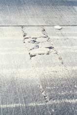
FIGURE 126
Distress Type CRCP 12—High
Severity Punchout
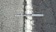
Description
Cracking, breaking, chipping, or fraying of slab edges within 0.3 m of the longitudinal joint.
Severity Levels
LOW
Spalls < 75 mm wide, measured to the face of the joint, with
loss of material or spalls with no loss of material and no patching.
MODERATE
Spalls 75 mm to 150 mm wide, measured to the face of the joint,
with loss of material.
HIGH
Spalls > 150 mm wide measured to the face of the joint, with
loss of material or is broken into two or more pieces or contains patch material.
CONTINUOUSLY REINFORCED CONCRETE SURFACES
FIGURE 127
Distress Type CRCP 13—Spalling of Longitudinal Joints
How to Measure
Record length in meters of longitudinal joint spalling at each severity level.
Only record spalls having a length of 0.1 m or more. Spalls that have been repaired by completely removing all broken pieces and replacing them with patching material (rigid or flexible) should be rated as a patch. If the boundaries of the spall are visible, then also rate as a high severity spall.
Note: All patches meeting size criteria are rated as patches.
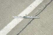
FIGURE 128
Distress Type CRCP 13—Close-up View of Low Severity Spalling of a Longitudinal Joint
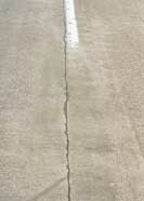
FIGURE 129
Distress Type CRCP 13— Low Severity Spalling of a
Longitudinal Joint
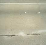
FIGURE 130
Distress Type CRCP 13—Moderate Severity Spalling of a Longitudinal Joint
Description
Seeping or ejection of water from beneath the pavement through cracks or joints. In some cases detectable by deposits of fine material left on the pavement surface, which were eroded (pumped) from the support layers and have stained the surface.
Severity Levels
Not applicable. Severity levels are not used because the amount and degree of water bleeding and pumping changes with varying moisture conditions.
How to Measure
Record the number of occurrences of water bleeding and pumping and the length in meters of affected pavement with a minimum length of 1 m.
Note: The combined quantity of water bleeding and pumping cannot exceed the length of the test section.
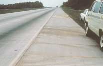
FIGURE 131
Distress Type CRCP 14—Water Bleeding and Pumping
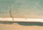
FIGURE 132
Distress Type CRCP 14—Close-up View of Water Bleeding and Pumping
Description
Joint seal damage is any condition that enables incompressible materials or a significant amount of water to infiltrate into the joint from the surface. Typical types of joint seal damage are:
Extrusion, hardening, adhesive failure (bonding), cohesive failure (splitting), or complete loss of sealant.
Intrusion of foreign material in the joint.
Weed growth in the joint.
Severity Levels
Not applicable.
How to Measure
Record number of longitudinal joints that are sealed (0, 1, 2). Record length of sealed longitudinal joints with joint seal damage as described above. Individual occurrences are recorded only when at least 1 m in length.
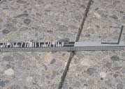
FIGURE 133
Distress Type CRCP 15—Longitudinal Joint Seal Damage