U.S. Department of Transportation
Federal Highway Administration
1200 New Jersey Avenue, SE
Washington, DC 20590
202-366-4000
Federal Highway Administration Research and Technology
Coordinating, Developing, and Delivering Highway Transportation Innovations
 |
| This report is an archived publication and may contain dated technical, contact, and link information |
|
Publication Number: FHWA-RD-02-083 Date: August 2006 |
Previous | Table of Contents | Next
The purpose of the test sections installed in Minnesota was to determine the influence of varying fly ash contents and air contents on the frost resistance of concrete. Fly ash contents of 15 and 30 percent (by mass) cementitious material as well as zero-fly ash mixtures were placed at various air contents. These sections were placed in October of 1992 and were monitored from 1994 through 1998. An additional survey was conducted in 2001 to obtain up-to-date performance information.
Caution should be exercised in evaluating results because the sections were not on trafficked pavement and did not experience de-icing salt application. However, snow was removed from the sections on a regular basis, so this pavement was certainly subjected to normal freeze-and-thaw cycles.
A summary of climatic exposure conditions for the Minnesota sections is given in table 1. These sections were subjected to severe winter freezing and thawing temperatures. The air freeze-thaw cycles range from 140 to 170 per year over this time period.
The Minnesota sections consist of 8 concrete pads of 4.6 meter (m) by 6.1 m at the Mn/ROAD test site maintenance yard. The sections were placed at the maintenance yard so that they would be subjected to environmental loads only. Each pad was quartered by making two saw cuts; hence, each section consists of 4 panels that are 2.3 m by 3.0 m.
The eight pads comprise eight test sections constructed of eight different mixes. These installations were developed to look at pozzolan content and air-void parameters. These experimental variables included 1.5, 2.5, and 5.5 percent air entrainment, and 0 and 30 percent fly ash by weight of cementitious material. A section containing a proprietary admixture that produces high-carbon concrete was also included (section 8). A summary of the various mix types is provided in table 2. One of the sections was the same as the conventional paving mix used on many of the Mn/ROAD concrete pavement sections (section 1).
| Month/Year | Monthly Low Temperature, °C | Days Below 0 °C (Air) | Days Below –18 °C (Air) |
|---|---|---|---|
| October 1992 | -6 | 11 | – |
| November 1992 | -9 | 25 | – |
| December 1992 | -24 | 29 | 6 |
| January 1993 | -27 | 30 | 12 |
| February 1993 | -24 | 28 | 9 |
| March 1993 | -19 | 30 | 7 |
| April 1993 | -8 | 9 | – |
| October 1993 | -3 | 11 | – |
| November 1993 | -16 | 25 | – |
| December 1993 | -26 | 30 | 7 |
| January 1994 | -33 | 31 | 17 |
| February 1994 | -27 | 28 | 12 |
| March 1994 | -12 | 27 | – |
| April 1994 | -8 | 13 | – |
| October 1994 | -2 | 4 | – |
| November 1994 | -13 | 20 | – |
| December 1994 | -19 | 31 | 1 |
| January 1995 | -24 | 30 | 5 |
| February 1995 | -24 | 28 | 9 |
| March 1995 | -20 | 18 | 4 |
| April 1995 | -15 | 9 | – |
| October 1995 | -4 | 3 | – |
| November 1995 | -17 | 29 | – |
| December 1995 | -23 | 31 | 5 |
| January 1996 | -31 | 31 | 18 |
| February 1996 | -36 | 28 | 8 |
| March 1996 | -23 | 28 | 8 |
| April 1996 | -6 | 20 | – |
| October 1996 | -9 | 9 | – |
| November 1996 | -24 | 27 | 4 |
| December 1996 | -33 | 31 | 9 |
| January 1997 | -28 | 31 | 16 |
| February 1997 | -21 | 28 | 3 |
| March 1997 | -20 | 28 | 1 |
| April 1997 | -13 | 16 | – |
| October 1997 | -11 | 8 | – |
| November 1997 | -20 | 26 | 2 |
| December 1997 | -21 | 30 | 1 |
| January 1998 | -31 | 31 | 8 |
| February 1998 | -14 | 18 | – |
| March 1998 | -17 | 24 | – |
| April 1998 | -2 | 3 | – |
*From Climatological Data. Minneapolis, MN, National Oceanic and Atmospheric Administration, www.noaa.gov.
| Mixture Number | Fly Ash Content, % | Fresh Air Content, % | Hardened Air Content, % (Entrained)* | 28-day Comp. Strength, megapascals (MPa) | Dynamic E, MPa |
|---|---|---|---|---|---|
| MN1** | 15 | 3.9 | 2.9 | 30.5 | 39,000 |
| MN2 | 15 | 2.7 | 0.9 | 26.5 | 39,000 |
| MN3 | 15 | 2.0 | 0.7 | 38.5 | 42,000 |
| MN4 | 0 | 2.5 | 1.4 | 36.5 | 39,000 |
| MN5 | 0 | 1.5 | 1.7 | 40.5 | 42,000 |
| MN6 | 30 | 3.8 | 1.4 | 29.0 | 38,000 |
| MN7 | 30 | 1.4 | 1.5 | 26.5 | 44,000 |
| MN8*** | HCC | 5.6 | 4.4 | 23.0 | 27,000 |
*From Resistance of Concrete to Freezing and Thawing, SHRP-C-391, Transportation Research Board.
**Minnesota Department of Transportation (MnDOT) Standard, except for air content.
***Proprietary high-carbon concrete admixture.
Additional data on the mixtures are given in tables 3 and 4.
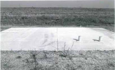
The Minnesota sections were constructed in October 1992 and first surveyed in October 1994. After 2 years of exposure, the test sections appeared just like new. Even the section with low air content and no fly ash (MN4 and MN5) showed no signs of freeze-thaw distress (no D-cracking, scaling, or popouts). The only minor distress present was some loss of fines from surface (not extensive enough to be called scaling) and a marred surface on sections MN6 and MN7, which appeared to be construction related as shown in figure 1. Most of the sections also had occasional minor joint spalling, which again appears to be construction related (i.e., sawing damage). Photos of each section in 1994 are provided in appendix A.
Figure 1. Test panels for mixture MN7 showing cores taken in 1994.
| Mixture | Description | Fresh Air (FA)(%) | Hardened Air % | Hardened Air (ent, %) | Spacing Factor (mm)* | Spacing Factor (ent, mm) | Specific Surface (mm-1) | Specific Surface (ent, mm-1) | Voids/ mm | Voids/ mm (ent) | Avg. Ch. Length (mm) | Avg. Ch. Length (ent, mm) | Paste- to-Air Ratio | 28-day f'c (MPa) |
|---|---|---|---|---|---|---|---|---|---|---|---|---|---|---|
| MN1 | MnDOT standard | 3.9 | 3.5 | 2.9 | 0.249 | 0.228 | 24.5 | 29.0 | 0.216 | 0.213 | 0.163 | 0.138 | 9.2 | 30.5 |
| MN2 | MN1 w/marginal air | 2.7 | 1.2 | 0.9 | 0.353 | 0.306 | 28.0 | 36.2 | 0.080 | 0.079 | 0.143 | 0.111 | 27.7 | 26.5 |
| MN3 | MN1 w/low air | 2.0 | 1.0 | 0.7 | 0.907 | 0.780 | 11.3 | 15.3 | 0.029 | 0.027 | 0.353 | 0.262 | 30.6 | 38.5 |
| MN4 | MN1 w/marginal air, no FA | 2.5 | 1.7 | 1.4 | 0.377 | 0.344 | 21.8 | 26.1 | 0.094 | 0.092 | 0.183 | 0.153 | 18.2 | 36.5 |
| MN5 | MN1 w/low air, no FA | 1.5 | 2.2 | 1.7 | 0.378 | 0.336 | 19.4 | 24.7 | 0.109 | 0.105 | 0.206 | 0.162 | 13.9 | 40.5 |
| MN6 | MN1 w/marginal air, 30% FA | 3.8 | 1.6 | 1.4 | 0.277 | 0.261 | 31.2 | 35.0 | 0.128 | 0.126 | 0.128 | 0.114 | 20.2 | 29.0 |
| MN7 | MN1 w/low air, 30% FA | 1.4 | 2.7 | 1.5 | 0.390 | 0.304 | 17.6 | 28.9 | 0.116 | 0.108 | 0.228 | 0.138 | 11.9 | 26.5 |
| MN8 | MnDOT experimental mixture | 5.6 | 7.3 | 4.4 | 0.215 | 0.166 | 20.7 | 33.9 | 0.379 | 0.370 | 0.190 | 0.118 | 4.6 | 23.0 |
*mm—millimeters
Note 1: All specimens cured 28 days (including 27 days in lime water).
Note 2: All air void measurements performed at Michigan State University.
| Mixture | Description | Durability Factor | Cycles to | Cycles to | % Mass Loss @ | % Dilation @ | |||||
|---|---|---|---|---|---|---|---|---|---|---|---|
| 60% RDM* | 0.1% Dilation | 60% RDM or 300 Cycle | 60% RDM or 300 Cycle | ||||||||
| Mean | Std. Dev. | Mean | Std. Dev. | Mean | Std. Dev. | Mean | Std. Dev. | Mean | Std. Dev. | ||
| MN1 | MnDOT standard | 98.9 | 0.4 | 300+ | – | 300+ | – | 0.1001 | 0.0066 | -0.0090 | 0.0216 |
| MN2 | MN1 w/marginal air | 98.4 | 0.6 | 300+ | – | 300+ | – | 0.1028 | 0.0206 | 0.0019 | 0.0019 |
| MN3 | MN1 w/low air | 97.6 | 1.1 | 300+ | – | 300+ | – | 0.1185 | 0.0083 | 0.0088 | 0.0019 |
| MN4 | MN1 w/marginal air, no FA | 97.9 | 0.3 | 300+ | – | 300+ | – | 0.0989 | 0.0205 | 0.0084 | 0.0024 |
| MN5 | MN1 w/low air, no FA | 92.5 | 3.2 | 300+ | – | 300+ | – | 0.0460 | 0.0084 | 0.0267 | 0.0142 |
| MN6 | MN1 w/marg. air, 30% FA | 99.2 | 0.5 | 300+ | – | 300+ | – | 0.1054 | 0.0123 | 0.0030 | 0.0050 |
| MN7 | MN1 w/low air 30% FA | 91.4 | 6.5 | 300+ | – | 300+ | – | 0.0731 | 0.0154 | 0.0209 | 0.0029 |
| MN8 | MnDOT experimental mixture | 98.4 | 0.3 | 300+ | – | 300+ | – | 0.0467 | 0.0506 | 0.0087 | 0.0053 |
Note 1: All specimens cured 28 days (27 days in lime water).
Note 2: All frost-resistance testing conducted in accordance with the American Association of State Highway and Transportation Officials (AASHTO)
T161 (American Society for Testing and Materials (ASTM) C 666) Procedure B, modified (use of cloth wraps).
RDM = Minnesota Road Design Manual
These sections were visually surveyed again in September 1995. There were virtually no observable changes in condition from 1994 other than the appearance of two popouts, one in MN3 and one in MN4. Both these sections have low air content, but the popouts are very minor. No signs of scaling or other deterioration were observed. One other change of note is the dense encroachment of vegetation all around the test pads.
Subsequent visual surveys of all test sections were conducted in 1996, 1997, and 1998. Very little deterioration occurred over this time period. The results of the final survey in 1998 are summarized as follows:
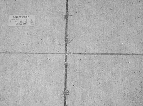
Section 1—15 percent fly ash, 3.9 percent air content —Very light surface scaling (visible sand particles are about 0.2 mm diameter) over the whole surface. See figure 2 for 1998 photograph of section 1.
Figure 2. Photograph of Minnesota test section 1 (1998). Most of the surface texture (brooming) is still visible. Sand particles up to 2 mm are visible in a very lightly scaled surface.
Section 2—15 percent fly ash, 2.7 percent air content—Same visual condition as section 1.
Section 3—15 percent fly ash, 2.0 percent air content—Similar very light surface scaling as sections 1 and 2, with a band about 400-500 mm wide in the direction of brooming having visibly less scaling.
Section 4—No fly ash, 2.5 percent air content—Similar very light scaling, with a band about 600 mm wide having less scaling.
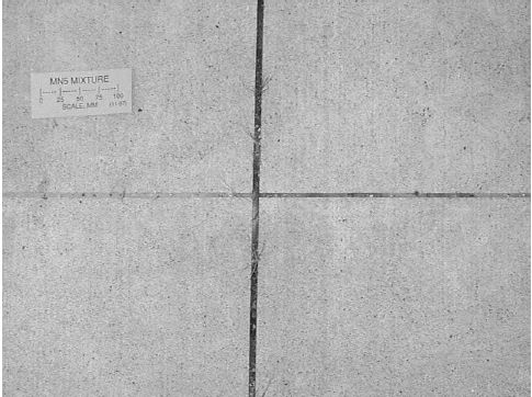
Section 5—No fly ash, 1.5 percent air content—Light scaling, with enough scaling in a few places to obscure the brooming marks. See figure 3 for photograph of section 5 in 1998.
Figure 3. Photograph of Minnesota test section 5 (1998). Scaling is slightly heavier than figure 2, and in some areas the surface texture (brooming) is obscured.
Section 6—30 percent fly ash, 3.8 percent air content—Scaling is generally very light, but about 5-10 percent of the total section area is scaled enough to obscure the brooming marks. The visible sand particles in these areas are in the 0.5-2 mm size range.
Section 7—30 percent fly ash, 1.4 percent air content—Light scaling over entire area. Streaks of scaling heavy enough to obscure broom marks are present throughout the section to a total of about 20 percent of the section area; these are generally adjacent to areas showing excessive paste (possibly an artifact of plastic placed on the concrete for curing before the concrete was initially set).
Section 8—High-carbon concrete (MnDOT experimental), 5.6 percent air content—Very light scaling throughout the section, with a few small streaks of unscaled concrete and also a few streaks of slightly heavier scaling.
It is important to note that none of these sections received any traffic loadings or de-icing salts over the 6-year period. The lack of de-icing salts may be of particular impact, as nearly all highways in freeze areas received large amounts, and this has been shown to have a very large effect on freeze-thaw scaling. (Okamoto et al., 1993)
Since the initial monitoring in 1994, two cores have been taken every year from each test section for the purpose of measuring their dynamic modulus. These cores were generally taken away from the joints and are not representative of concrete near the joints. The cores were dried at approximately 50 percent relative humidity and 22 °C to constant mass and were tested in accordance with ASTM C 215 to determine the dynamic modulus of elasticity. The results are summarized in table 5. There does not appear to be any significant change in the condition of the interior concrete as measured by changes in core stiffness. This would suggest that there has not been any internal deterioration in the concrete from construction to 1998 despite the harsh winter conditions at this Minnesota site. It is not known what damage existed near the joints where more water could saturate the concrete.
| SHRP C-203 Designation | Core Dynamic Modulus, MPa | ||||
|---|---|---|---|---|---|
| 1994 | 1995 | 1996 | 1997 | 1998 | |
| MN1 | 38,829 | 36,274 | 38,125 | 38,601 | 38,453 |
| MN2 | 39,248 | 39,229 | 40,411 | 39,630 | 38,317 |
| MN3 | 42,286 | 40,652 | 41,676 | 41,740 | 41,902 |
| MN4 | 38,710 | 39,201 | 38,088 | 40,689 | 38,741 |
| MN5 | 41,745 | 40,513 | 41,289 | 40,127 | 41,410 |
| MN6 | 38,363 | 40,473 | 40,602 | 40,027 | 40,941 |
| MN7 | 44,231 | 44,038 | 44,879 | 44,283 | 47,191 |
| MN8 | 27,519 | 27,376 | 28,435 | 29,068 | 28,553 |
The Minnesota sections are exposed to environmental effects only, and they do not show any significant degradation in condition. Minor scaling was visible on most of the slabs, consisting mostly of loss of fines from the surface. The level of scaling was similar in most sections, but at least two sections seemed to exhibit somewhat noticeable differences in condition. Section 8, which is the MnDOT experimental mix that had the highest fresh air content (5.6 percent), did not show any signs of scaling. Section 5 appeared to have slightly more scaling than other sections. Section 5 contains only 1.5 percent air and no fly ash. The field observations were generally consistent with what may be expected based on mix design, but section 7, which had the lowest fresh air content (1.4 percent), had very little scaling. Section 7, however, did contain twice the amount of fly ash provided in the control mix (30 percent).
Cores were taken from Minnesota test panels MN1, MN2, and MN3. The cores were allowed to air dry for 8 months and were then cut into freeze-thaw test specimens. The specimens were soaked in calcium-saturated water for 7 days and then tested in rapid freezing and thawing (AASHTO T161, Procedure C). Results of the freeze-thaw tests are presented in table 6, along with the original freeze-thaw results (from specimens prepared during test section construction) and the air-void parameters measured at the time of construction.
| Mixture | Plastic Air % | Hardened Air % | Specific Surface mm2/mm3 | Spacing Factor mm | Original Durability Factor | Followup Durability Factor |
|---|---|---|---|---|---|---|
| MN1 | 3.9 | 3.5 | 24.5 | 0.249 | 99 | 100 |
| MN2 | 2.7 | 1.2 | 28.0 | 0.353 | 98 | 39 |
| MN3 | 2.0 | 1.0 | 11.3 | 0.907 | 98 | 16 |

