U.S. Department of Transportation
Federal Highway Administration
1200 New Jersey Avenue, SE
Washington, DC 20590
202-366-4000
Federal Highway Administration Research and Technology
Coordinating, Developing, and Delivering Highway Transportation Innovations
 |
| This report is an archived publication and may contain dated technical, contact, and link information |
|
Publication Number: FHWA-RD-97-146 Date: NOVEMBER 1997 |
Previous | Table of Contents | Next
In this chapter, brands and makes of equipment are not specified; rather, the functions of the equipment and the reasons the equipment is required are described and explained. The successful operation of a petrographic laboratory is dependent on the skill, knowledge, and judgment of the petrographers and petrographic technicians and the quality, sufficiency, and operating convenience of the equipment available to these people. The better the quality of the equipment is, the more efficient and accurate the results of the petrographic examinations will be. Table 21 is a list of the equipment needed in a petrographic laboratory. Much of this equipment is demonstrated in Walker (1988).
Table 2-1
EQUIPMENT FOR PETROGRAPHIC LABORATORY
For Preparation of Slices
For Production of thin-sections
For Examination of Specimens
Expendable Materials
2.2 FOR SAMPLE PREPARATION ROOM
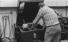
The sample preparation room is a dirty room because it is usually the room to which new specimens, complete with any adhering dust or soil, including concrete in all stages of disintegration, are brought and in which loose grinding compounds and lapping oils are stored and used. Water, oil, specimen fragments, mud, and grinding compounds accumulate on the floor and may be tracked to other portions of the building. This room requires periodic cleaning and sorting to make it possible to work in.
The following equipment is needed in the sample preparation
room:
Exhaust system. For exchanging the air frequently and ridding the
room of the chemical fumes and oil vapors produced from cutting, lapping,
and cleaning specimens.
Table. For sorting and labeling specimens and preparing them for preparation procedures. Equipment for marking specimens, paper, pens, and pencils should be available at this table.
Hood. For enclosing any area where strong solvents (e.g., acetone, 1,1,1, trichloroethane) and epoxy components are stored and used.
Running water. For cooling and lubricating some of the saws and the drill press. Usually, it is most convenient to have adjustable, mixable, hot and cold water permanently supplied to each piece of equipment. Hoses that drape across the floor and must be reattached to each piece of equipment as it is put into use are a safety hazard and are inefficient. In many cases, the operator's hands must stay in the running water for a long period of time. Thus, although the main purpose of the water is to remove heat from the specimen, it must be possible to adjust the water temperature so that the operator is comfortable and can maintain a firm grip on the specimen being shaped.
Sink. For washing hands and pieces of equipment.
Floor drains. For draining spilled and splashed water. A large sump should be placed under the areas where oil may be spilled.
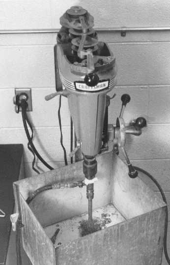
Watercooled drill press and Diamond-edged drill bits (Fig. 21). For fabricating small cores of rock or concrete. Bits should be of internaldiameter sizes required for any tests using small cores of rock. This item will not be required unless the preparation of rock specimens for tests such as those specified in ASTM C 277 is a function of the petrography laboratory. Quantity: 1.
| Figure 2-1 WATERCOOLED DRILL PRESS. A = water supply hose; B = drill bit; C = splash guard. |
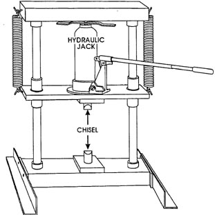
| Figure 2-2 ROCK TRIMMER. With chisel points and hydraulic jack to apply up to 5 tons of force. |
Rock trimmer (Fig. 22). A hydraulic press that by means of opposing chisel points produces controlled cracks in rock, concrete, and similar materials.
Apparatus and materials for the preparation of surfaces of HCC specimens for microscopical observation are described in ASTM C 856, "Apparatus." Other apparatus may be equally suitable. Water should be used as little as possible on portions of HCC that are to be examined microscopically. Water dissolves certain components of HCC (see 6.3.3). With this in mind, whenever a choice is possible, equipment for sawing concrete that uses an oil bath should be selected rather than equipment that uses running water or a water bath containing a rust inhibitor. The diameters listed for the rotary saw blades reflect the fact that the depth of cuts made with a rotary saw cannot exceed the distance from the supporting central plate to the edge, a distance that is always less than half the diameter of the saw blade. The flatness and accuracy of the saw blade are greatest at the rim, where it moves with the greatest velocity relative to the specimen. Some blades thicken or bow in the middle and cause binding. The polishing wheel mentioned in ASTM C 856 is not required for the production of finely lapped concrete surfaces since lapped surfaces are not polished. Polished surfaces are not desired because they act as mirrors and reflect images at all angles of incidence.
The following equipment is needed for shaping and lapping
slices:
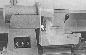
Watercooled, Diamond-edged, rotary saw with an overhand arm (Fig.
23). For reducing large fragments and long cores and cylinders to sizes
that may be held in the vise of the next saw. The 14in. diamond-edged blade
is usually slotted into wide teeth. The saw is cooled with running water
to allow specimens to be hand held for quick setup and obviate the need
for a cover. Both hands are often needed to hold the specimen and roll the
table. The footpedal control for adjusting the height is a necessity. Quantity:
1.
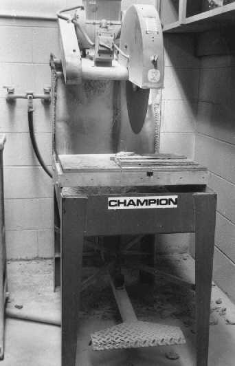
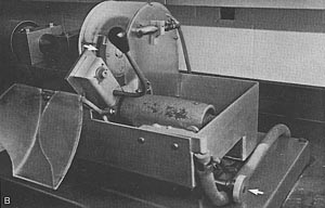
Large, oil-cooled, Diamond-edged, rotary saw (Fig. 2-4). For cutting specimens . The 24in. (minimum) Diamond-edged, smooth-edged blade produces a smooth cut with few ridges and minimizes the difficulty of producing finely lapped surfaces. A vise that holds the specimen firmly and automatically moves it into the saw is an integral part of this equipment. The saw is covered to contain the splashing oil and oil vapors. Quantity: 1 (minimum).
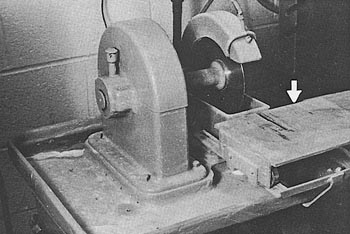
Diamond-edged trim saw. For shaping small specimens of rock or concrete, such as thin-section blanks. The saw in use at VTRC (Fig. 2-5) is water cooled, but an oil-cooled saw is preferable so that specimens are not exposed to water that might dissolve certain phases in concrete. The Diamond-edged blade should be 8 in. or less in diameter. Quantity: 1.
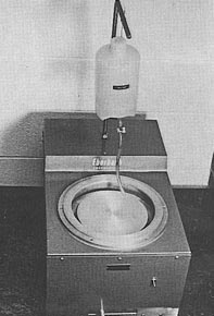
Bench lap(Fig. 2-6). For smoothing surfaces of handheld specimens of rock or concrete. The usual lubricant is water added by hand or dripped from an overhead
| Figure 2-3 WATERCOOLED, DIAMOND-EDGED, ROTARY SAW WITH OVERHAND ARM. The 14in. blade is diamond-edged and slotted into wide teeth. The foot pedal controls the height of the saw. |
 |
 |
| Figure 2-4 LARGE, OIL-COOLED, DIAMOND-EDGED, ROTARY SAW. A. The smooth-edged blade, at least 24 in. in diameter, runs in an oil bath. B. Interior vise that holds specimen firmly and automatically moves it into the saw. |
| Figure 2-5 ROTARY SAW WITH THIN, DIAMOND-EDGED, SMOOTH-EDGED BLADE. Diameter of 6 in. The arrow points to the sliding table on which the specimen can be braced. |
| Figure 2-6 BENCH LAP. Diameter of 8 in. For rough grinding rock and concrete specimens. The suspended bottle is for water or another lubricant. Grinding compounds may be shaken like salt from plastic bottles with a pierced cover. |
container. The grinding compounds are usually dispensed from small shakers. Quantity: 1.
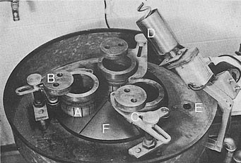
Rotating laps. For producing finely lapped surfaces for microscopic examination and air-void analysis. The laps should be fabricated of cast iron and radially grooved to provide drainage. The equipment includes an adjustable timer and automatic feed for the slurry of lapping oil and grinding compound. A lap 16 in. in diameter will handle three 4in, specimens or two 6in. specimens. The lapping equipment includes slotted, rotating, sample-holding rings (sized to fit common slice sizes), yokes to hold the rings, and cover plates to rest between the slice and its weight. The lapping of concrete or rock slices is time-consuming. Two laps speed up operations. If there is only one horizontal lap wheel, great care must be taken to clean the iron wheel and associated equipment carefully (such as the feeder for grinding compound) whenever a change is made to a finer compound. A very small amount of a coarse grit left in the equipment can significantly damage a lapped surface produced with fine grits. The finest grinding compound should be used on one lap, and all coarser grits on the other. The lap wheels (Fig. 2-7) should be sturdy and have durable bearings to withstand the stresses of unbalanced samples and heavy weights. Quantity: 2.
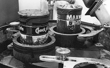
Weights (Fig. 2-8). For lapping slices smoothly. Weights fit on the back of the slices, loosely inside the rings. The weights press the specimen firmly against the lap to prevent the lapping away of the softer material and leaving the hard material as high spots. The weight increases the wear on the high (hard) portions of the specimen and prevents a buildup of grinding compound under the softer portions. Without the weights, the softer portions will be worn away more deeply. The
| Figure 2-7 LAP. Diameter of 16 in. A = rotating slotted specimen holder; B = cover plate to set on top of specimen; C = guide yoke that retains specimen holder; D = gritslurry cup mounted on its motor and containing spiral agitatorpump; E = drain; F = grooved lap. |
| Figure 2-8 WEIGHTS. For lapping slices smoothly. Weights fit on the back of the slices, loosely inside the rings. Here, coffee cans of appropriate diameter weighted with lead shot are used. |
weights should cover nearly all the back of the specimen and should weigh
14 to 16 lb for a specimen 4 in. in diameter and 16 to 18 lb for a specimen
6 in. in diameter. Coffee cans of appropriate diameter weighted with lead
shot have been found satisfactory. Quantity: The number of specimens it
is possible to lap at one time.
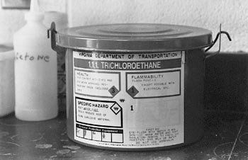
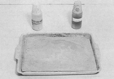
Safety-approved container (Fig. 2-9). For cleaning specimens. Specimens are cleaned in solvents, such as acetone or 1,1,1, trichloroethane, to remove oil and grinding compound accumulated during lapping.
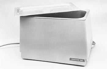
Ultrasonic cleaner (Fig. 2-10). For cleaning specimens. The cleaner should be of sufficient size to submerge easily the largest lapped specimen that will require cleaning. The cleaner bath must be of a material that can hold acetone or 1,1 ,1, trichloroethane. Quantity: 1.
| CAUTION: It has been reported that use of ultrasonic cleaning equipment may be harmful to the surface of concrete specimens; therefore, such treatment should not be used without care and experimentation with the specific frequencies of the equipment (ASTM C 457). |
| Figure 2-9 SAFETY-APPROVED CONTAINER FOR CLEANING OF SPECIMEN |
| Figure 2-10 ULTRASONIC CLEANER The tank is of a material that will resist most solvents. |
To fabricate a specimen chip of concrete or rock that will fit the glass that will be used to support the thin section will usually require the use of at least one of the two large saws and the small trim saw. The room that is used for the further fabrication of thin sections should be isolated from the operations of the preparation of lapped slices and requires an efficient exhaust system or two hoods because the cutting and grinding of thin-sections to the required thickness produces an oil vapor and the production of thin-sections requires the use of epoxy (toxic in large quantities).
The method any particular laboratory uses to produce thin-sections will depend on the equipment available and the preference of the technical personnel. Pacific Northwest Laboratories of Battelle, Richland, Washington, recommended the use of a belt sander and a bench lapping machine with diamond impregnated laps Beauchamp, Williford, & Gafford, 1972). Labor fur Praparation and Methodik, Beinwil am See, Switzerland, recommended the use of a diamond tooled milling machine (Wilk, Dobrolubov, & Romer, 1974). VTRC has Ingram Ward thin-section machines.
2.4.2 For Examination with Petrographic Microscope
Thin-sectioning equipment. For producing thin-sections of rock and similar materials for examination with the petrographic microscope. This manual describes the use of Ingram Ward equipment (Fig. 2-11). The instructions can probably be adapted for use with any type of thin-sectioning equipment that permits variability in section thickness and thus will make possible ultrathin and extra thick sections. Part A of the set is a rotating cutoff saw with a very thin blade used to slice off excess specimen material, thus reducing the specimen chip (mounted on a glass slide and held in a vacuum chuck) to 50 to 30 um in thickness. Generally, the thinner the slice of specimen chip remaining on the glass slide, the better. Part B of the set holds the specimen in another similar vacuum chuck and permits it to be moved carefully and evenly over a rotating, diamond-bearing, cupped, ceramic grinder to grind it to nearly the desired thinness. The relative position of the chuck to the saw or grinder can be adjusted with a small dial at the righthand end of each piece of equipment. The lubricant (denatured kerosene with 1/lOth part motor oil) is collected in the surrounding tank and pumped to the top of the saw or wheel to cool and lubricate the work. Quantity: 1 set.
Glass plate firmly supported in a flat pan (Fig. 2-12). For catching spilling slurry when thin-sections are hand lapped after they have been cut and ground on the Ingram Ward equipment. Ordinary window glass is usually sufficient. Used for final grinding of ordinary and intermediate grinding of fluorescent ultrathin sections for use with the petrographic and P/EF microscopes. Quantity: 1.
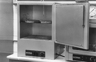
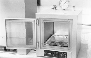
Drying oven (Fig. 2-13). For evaporating water or lapping oil from slices, thin- sections, or rock fragments and curing the epoxy of specimens impregnated for thin- sections. Vented to allow the escape of vapors. A thermometer is mounted near the center of the oven. Steam must not form in the HCC; therefore, the temperature in the oven must be thermostatically controllable (adjustable to less than 100°C). Quantity: 1.
 |
 |
| Figure 2-11 INGRAM-WARD THIN-SECTIONING EQUIPMENT. A. Diamond-edged cutoff saw with very thin blade (see arrow) used to slice off excess specimen material. B. Diamond-bearing , cupped ceramic grinder (see top arrow). The handle and chuck permit the specimen to be moved carefully and evenly over the rotating, diamond bearing, cupped, ceramic grinder. The relative position of the chuck to the saw or grinder can be adjusted with a small dial (see bottom arrow) at the right hand end of each piece of equipment. |
| Figure 2-12 GLASS COATED WITH GRINDING COMPOUND SLURRY. The pan used to catch the grinding slurry which overflows the edge of the glass. The two plastic bottles have holes in the screw on covers and waxed paper cups for dust covers. The bottles are used for grit and lubricant slurries. |
| Figure 2-13 DRYING OVEN. Thermostatically controlled. |
2.4.3 For Examination with Polarizing/Epifluorescence Microscope
Vacuum oven (Fig. 2-14). For vacuum impregnating thin-section stock with epoxy and slow, even drying of specimens. For fluorescence, fluorescent dye is add ed to the epoxy. Quantity: 1.
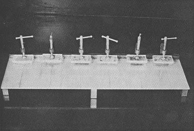
Set of clamps mounted on a sturdy metal plate (Fig. 2-15). For cementing an impregnated thin-section chip to the final, welled, glass slide. Quantity: 1.
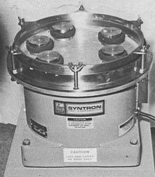
Vibrating lap with weights (Fig. 2-16). For producing the final surface of fluorescent ultrathin sections. The thin-sections are attached to the bottom of the weights. The circular pan is lined with Pellon PaNW, a specially formulated lapping pad, which is coated with diamond paste thinned with a thin oil. Quantity: 1.
 |
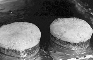 |
| Figure 2-14 VACUUM OVEN. A. With thin-section stock in liquid dyed epoxy in a small disposable dish. Door will not stay shut without the vacuum. B. Closeup of bubbling of liquid epoxy as vacuum removes air and water from specimen. |
| Figure 2-15 MOUNTED SET OF CLAMPS. The little rectangles of lucite are used to distribute stress (Walker & Marshall, 1979). |
| Figure 2-16 SYNTRON VIBRATORY POLISHER AND WEIGHTS. Complete with sponge rubber bumpers (Walker & Marshall, 1979). |
2.5 FOR EXAMINATION OF SPECIMENS
The room in which specimens are examined is also where the microscopes are stored and used and should be as close to a "clean" room as can be managed without the use of special clothing. A worker whose hands or clothing is contaminated with grinding compounds, excessive dust, lapping oil, grease, soil, or materials used to mix concrete should remove the contaminants from his or her person before approaching a microscope. It is best if the air in the room is under positive pressure and an anteroom is equipped with an exhaust system to create the concomitant negative pressure. The room should be furnished with tables and microscope benches and a number of adjustable height stools and chairs.
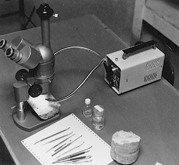
Stereomicroscope (Fig. 2-17). For conducting a general examination of specimens. May also be used in the quantitative determination of air-void parameters. This is the instrument most used by concrete petrographers. The stereomicroscope should have a magnification variable between 25 and 120 diameters. The higher magnifications are attainable with a 2X accessory lens below the objective. It is most convenient to have a zoom objective, but excellent observations can be made with turret-mounted objectives. It is very tedious and annoying to have to change objectives by dismounting them and remounting them. The eyepieces should be the widefield type. A measuring reticle in one eyepiece can be convenient (must be calibrated for
| Figure 2-17 STEREOMICROSCOPE WITH LIGHT SOURCE AND ACCESSORIES |
each magnification). By the use of this microscope, decisions are made concerning concrete quality and the planning of further testing. If there is a difference in the quality of the microscopes available, the one with the least distortion and the widest field of view should be the one used in the quantitative determination of air-void parameters. Quantity: at least 2.
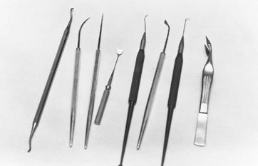
Microtools. For measuring, manipulating, and removing portions of slices of concrete and manipulating the grains of grain mounts under any kind of magnification. The most useful microtools will probably be ones that have been fabricated in the petrographic laboratory (Fig. 2-18). Sets of microtools are commercially available, but they often do not meet the needs of the concrete petrographer. The best sets have a variety of needles, shovels, and scrapers. The tiny tools must be small enough to use in the cracks, crevices, and voids of concrete but must be strong and resilient to resist breaking. Some of these sets are constructed with the microtools as detachable pieces that screw or clamp into a handle. Such sets should have more than one handle. The needles used for biological dissection are usually strong enough, but the point thickens so rapidly that the tool may not be of use in tight cracks and voids. Sewing needles with a handle of a section of a small dowel rod can be very useful. They are strong and sharp and come in a variety of sizes. Often, what is required is an assortment of needles with bends of different radii, well within the working distance of the microscope, to allow the needle to attack the concrete from a variety of angles. Such needles are commercially available for biological microscopy but may not be strong enough to pick out reaction products and small pieces of aggregate from concrete. Duplicate tools should be obtained so that breakage will not cause a delay in the progress of the work.
| Figure 2-18 MICROTOOLS. These include needles shovels, and scrapers small enough to be useful in the cracks and crevices of concrete and fit in the working distance under the stereomicroscope . The arrow indicates a small scale engraved on very thin, flexible metal attached to a thin rod that is attached to a handle. The scale has 5 mm marked into tenths of a millimeter on one side and 1 tenth of an inch marked into 5 thousandths of an inch on the other. |
The most unreplaceable commercially available microtool is a small scale engraved on very thin flexible metal attached to a thin rod, which is attached to a handle. The scale may have 5 to 10 mm marked into tenths of a millimeter and 1 to 2 tenths of an inch on the other side marked into 5 thousandths of an inch. The flexibility allows better positioning of the scale. The thinness allows the scale to be more nearly in the same focal plane as the item examined. Unfortunately, the solder joint between the flexible metal and the stiff rod connection to the handle may be very fragile. It is good to have a replacement scale available. For less precise measurements, a transparent scale, usually SI, used by the microscopist viewing through the scale with the markings down on the concrete (to allow best focus) is useful. Such scales may be found in stationery and variety stores.
Excellent picks, miniature knives, shovels, and scrapers can usually be obtained from most dentists if a request for used tools is made. These tools are strong and designed for approaching the work area in close quarters. They may require sharpening and reshaping to suit the needs of the concrete petrographer. For this purpose, a stick or two of abrasive dressing compound are useful. These tools may corrode in the presence of chemicals and must be kept clean and sharp. Quantity: minimum of 1 each, many items.
Equipment for air-void determinations. This equipment is described in Chapter 6.
Petrographic microscope. This microscope is described in Chapter 12.
P/EF microscope. This microscope is described in Chapter 13.
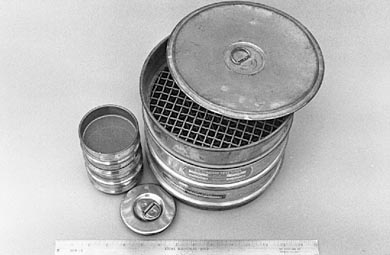
Sieves (Fig. 2-19). For sorting aggregate particles (pebbles, sands, and crushed fragments) by size and preparing specimens for microscopic examination. Sieves should comply with the requirements of ASTM E 11. Two sizes of frames are required: 8 in. and 3 in. Both sets of sieves should include standard covers and pans. The 8in. size is used for sizing and sorting aggregate material to determine compliance with the client's specifications and prepare aggregate specimens for various testing procedures. The 8in, set should include the mesh sizes necessary to determine the compliance of an aggregate with the client's specifications. If other laboratories that are concerned with aggregates are on the premises, this size of sieve will probably be available. The 3in, size is used to prepare sands and rock and concrete fragments for grain mounts or other microscopic studies. The 3in, set should include the mesh sizes of the larger that are smaller than 3/8 in. (9.5 mm) and an assortment similar to the following:
VDOT Designation ASTM (SI) Designation No. 30 600 µm No. 40 425 µm No. 60 250 µm No. 100 150 µm No. 200 75 µm No. 400 38 µmOther equipment. Various instrumental methods of analysis such as x-ray diffraction, elemental analysis by x-ray dispersion, scanning electron microscopy, and certain wet chemical tests may be employed in the identification of the raw materials and reaction products and deleterious substances that may be associated with
| Figure 2-19 SIEVES. Types of sieves used in examination of concrete and concrete materials, 8in. and 3in. sizes. |
HCC. Each of these methods requires careful work; detailed study; long practice; usually a wide assortment of reference books, charts, and reference samples; and often very expensive equipment.
| WARNING: Persons unfamiliar with the hazards of these compounds are referred 1 to the Chemical Safety Data Sheets published by Manufacturing Chemists Association, Inc., 1825 Connecticut Avenue, NW, Washington, DC 20009, or to the Materials Safety Data Sheet that should be obtained from the supplier of the particular compound. |
Water should not be used on any surface of an HCC specimen that is to be examined under magnification. The lubricant used for cutting and lapping specimens should be low viscosity, water-free lapping oil, such as denatured kerosene mixed with 1/10th part motor oil. The motor oil lessens the production of vapors from the kerosene. A number of light oils are sold specifically as lubricants for cutting with diamond saws. One example is the odorless, stainproof, diamondsaw lubricant sold by Lapidabrade, Inc., Havertown, Pennsylvania. Specialized lubricants are required for grinding and polishing thin-sections with diamond grinding compounds. One of these might be Formula C from the Glennel Corporation, Chester Springs, Pennsylvania.
Oil-based lubricants will not dissolve reaction products and secondary minerals as readily as will waterbased lubricants. It is convenient to use a lapping lubricant that will evaporate and leave the surface of the specimen oil free. At magnifications such as are used in the analysis of concrete, an oil film can obscure the exact edges of voids and aggregate particles. The evaporation of the oil may be hastened by treatment in a warm (<700C), not hot, drying oven. High heat can crack the concrete specimen or heat the oil to its flash point. The oil drained from the laps may be reused after filtering and decanting.
For preparing finely lapped surfaces on concrete specimens. The grit numbers and sizes listed are given only as a guide. The grinding compounds produced by one manufacturer may vary from those produced by another.
No. 100 (nominal 150 µm) siliconcarbide abrasive
No. 220 (nominal 75 µm) siliconcarbide abrasive
No. 320 (nominal 35 µm) siliconcarbide abrasive
No. 600 (nominal 17.5 µm) siliconcarbide abrasive
No. 800 (nominal 12.5 µm) siliconcarbide abrasive
5 -µm aluminum-oxide abrasive
0.3 µm Linde, an aluminum oxide grinding compound. For using in the
epoxy of impregnated thin-sections to prevent excess wearing of the epoxyrich
areas of ultrathin sections. The distinctive particle shape will not be
confused with any ingredient of concrete or aggregate.
oil-soluble diamond paste compounds, heavy concentration
(those from Penn Scientific Products have been found satisfactory)
-4-8 µm, U.S. Bureau of Standards Grade No. 6, indigo colored
-2-4 µm, U.S. Bureau of Standards Grade No. 3, violet colored
-0-2 µm, U.S. Bureau of Standards Grade No. 1, white colored
Fluorescent dye. For inclusion in the impregnating epoxy of ultrathin sections to create fluorescence in the voids and cracks. This is available only as samples (believed to be a paint ingredient). The dye presently used is Fluorol Yellow 088, available as samples from BASF Wyandotte Corp., Holland, Michigan. This dye dissolves completely in epoxy; no dye particles can be seen at 600X magnification, and the epoxy is evenly colored by the dissolved dye.
Impregnating epoxy. For strengthening thin-section stock and carrying fluorescent dye. Epo-Tek 301-2 from Epoxy Technology, Billerica, Massachusetts, is a good impregnating epoxy. It dissolves the dye completely. It has sufficient shelf life to be useful after a year or so, although it may have to be warmed a little. It has a sufficient pot life to remain fluid through several hours of vacuum impregnation and can be formulated to cure with a little heat treatment and over several days to a hard brittle substance that shows no plasticity. When properly cured, the hardened epoxy is not soluble or softened in oil, alcohol, acetone, or 1,1,1, trichloroethane.
Mounting epoxy. For attaching the smoothed thin-section stock to the final supporting glass slide. The mounting epoxy presently used can be either Epoxide from A.B. Buehler, Lake Bluff, Illinois, or Section Lok epoxy mounting medium from Microtech Engineering Laboratory Inc., Clifton, Colorado. Of the two, the Section Lok product has the longer shelf life.
Flat glass petrographic slides (27 by 46 mm). For mounting thin-sections and grain mounts for examination with the petrographic microscope. A standard item in most scientific catalogs. The slides used for temporary grain mounts can be cleaned and reused.
Welled glass petrographic slides (27 by 46 mm). For mounting ultrathin section chips. The edge of the well provides some protection from the tearing stresses of the procedures (A.B. Buehler Co., Lake Bluff, Illinois).
Carpet tape or other strong, double-sided tape. For attaching thin-sections to the bottom of weights.
Carnauba wax, or colorless nylon fingernail hardener. For impregnating fragile concrete.
Pens. For fine marking concrete slices. The pen used should be such that when the inky point is positioned on a crack a very small portion of the ink will flow into the crack and be drawn along the crack and will thus indicate the next direction of the crack.
10% hydrochloric acid. For etching entire slices or
portions of slices.
Notebooks. For recording observations.
Glass trays. For etching or other chemical treatment of finely lapped
specimens.
Dropper bottles or rods. For dropping acid and water.
Glass dishes. For using in chemical tests.
Absorbent cotton, tissues, paper towels, etc.
Index of refraction oils. For determining the optical properties
of minerals and other translucent substances with polarized light microscopy.
The oils should range in index from 1.40 to 1.50 in steps of 0.04, from
1.500 to 1.600 in steps of 0.002, and from 1.600 to 1.700 in steps of 0.01.
Index oils change with age and must be checked periodically with a refractometer
or standard solids.
Disposable 12inch liners for the vibrating lap. Pellon PaNW, polishing pads.
Disposable plastic Petri dishes, 60 mm in diameter, 20 mm in depth. For potting thin-section specimens in fluorescent dyed epoxy.
Equipment for specific tests. Examples are the concrete molds and the length comparators required by certain ASTM procedures. The equipment required for the uranylacetate fluorescence test for the presence of alkalisilica gels is listed in 10.2.3.
Reference specimens. For permitting comparisons between materials under study and carefully labeled and documented specimens in a reference collection. Two general kinds of materials should be included in such a collection: (1) raw materials from which concrete is fabricated, and (2) various kinds of HCC in both rough fragments and finely lapped slices. If storage space is limited, photographs may have to be substituted for the larger specimens. Ideally, enough of each specimen should be available for various destructive testing procedures. Some of the items to be included are listed in Tables 2-2 and 2-3.
Aggregates
Coarse
Fine
Those are known to have caused problems (e.g., alkalireactive aggregates,
aggregates that create a high water demand)
Particulate Admixtures (in moisture resistant containers)
Fly ash
GGBFS
Silica fume
Other
Types of Cement Approved for Use (in moisture resistant
containers)
Portland cement
Portland cement blended with slag, fly ash, etc.
Other cements, such as GGBFS
Note: Specimens should include as many types of each as are available locally. They should be labeled as to source and type and stored in transparent containers.
1. Each of the materials listed in Table 2-2 used in the proper manner in hardened HCC mixtures
2. Materials used in varying amounts:
3. Various forms of distress (in large fragments) according
to occurrence in the area and accompanied by photographs of the surface
condition: