U.S. Department of Transportation
Federal Highway Administration
1200 New Jersey Avenue, SE
Washington, DC 20590
202-366-4000
Federal Highway Administration Research and Technology
Coordinating, Developing, and Delivering Highway Transportation Innovations
 |
| This report is an archived publication and may contain dated technical, contact, and link information |
|
Publication Number: FHWA-RD-97-146 Date: NOVEMBER 1997 |
Previous | Table of Contents | Next
3.1 OVERVIEW
Clients submit a specimen to the petrographic laboratory for a variety of reasons. Some of these reasons are listed in Table 3-1. The different types of specimens that may be submitted are listed in Table 3-2. For HCC, the word specimen is used and the word sample is usually avoided because the specimen is seldom a truly representative sample of the HCC placement. Clients may also submit a suite of related specimens. For the sake of brevity, I use the word specimen even when a suite of specimens is meant.
Table 3-1
REASONS PETROGRAPHIC SERVICES ARE REQUESTED
AND CORRESPONDING PLANS FOR ANALYSIS
Table 3-2
TYPICAL TYPES OF SPECIMENS
No matter what the reason or type of specimen, four general procedures are performed for each specimen received for petrographic examination:
1. Formally receive the specimen.
2. Perform the initial examination.
3. Make a plan for analysis of the specimen.
4. File the appropriate documents.
Upon receipt of a specimen, six tasks are performed, as listed in Table 3-3.
Table 3-3
PROCEDURE-FORMAL RECEIPT OF SPECIMEN IN LABORATORY
1. Study the accompanying documentation, and carefully consider any oral instructions from the client.
2. Make written notes concerning the condition of the specimen and any obvious forms of deterioration.
3. Make sure the specimen is suitable for the analysis requested by the client.
4. Make sure the specimen agrees with its accompanying documentation.
5. Mark and log the specimen.
6. Fill out a "request for petrographic services form."
1. Study the accompanying documentation, and carefully consider any oral instructions from the client. Take careful note of any indication that the results of the analysis are needed within a short time or that they may be required as evidence in any litigation.
2. Make written notes concerning the condition of the specimen and any obvious forms of deterioration.
3. Make sure the specimen is suitable for the analysis requested by the client (see Appendix B). If, for example, the client requests an analysis of the air-void parameters or a complete petrographic examination and the specimen was reduced to a rubble or thoroughly cracked during sampling or compressive strength testing, it will be impossible to prepare the necessary representative lapped surface. If the client's concern is the lithology of the aggregate, such a specimen will be suitable. If the specimen is only slightly cracked or can be easily glued back together, it is often possible to prepare a lapped surface of at least a portion of the specimen. The cracking from testing will make it impossible to study some of the causes of deterioration because it will be impossible to distinguish testing cracking from the cracking indigenous to the placement. If there is reason to suspect that the specimen has not been properly cared for (improper storage and curing, treated roughly, broken, etc.) and its condition will not allow an accurate reply to the client's request, the use of the specimen will be impossible. If the specimen is smaller than the petrographer thinks necessary for the examinations requested (core less than 3 in. in diameter, small irregular fragments) or if, for any reason, the specimen is such that adequate data cannot be obtained from it, explain the effects of these conditions on the data that will be obtained to the client and request a better specimen. In all cases where a patched, undersized, or otherwise imperfect specimen must be used, discuss the matter in the final report on the specimen.
4. Make sure the specimen agrees with its accompanying documentation. The documentation should indicate the source of the specimen, the date of the placement, the amount of traffic it has suffered (in the case of a pavement surface), the method of removal from the placement, any testing procedures that have been performed, and any results of such testing. If the documentation does not discuss or ask questions concerning any unusual features that are easily seen, sufficient data (data related to the specific questions asked by the client) concerning the specimen are not included, or sufficient information concerning the billing of the charges is not received, contact the client for further explanatory material.
The documentation and oral exchanges between the petrographer and the client should make clear the proposed use of the data obtained by the petrographic examination. If the data obtained from the specimen will become part of a legal controversy, note this fact and consider it throughout the entire analysis. Certain short cuts may be considered permissible for work done within one organization, but data collected for presentation by an expert witness must be gathered according to the exact procedures detailed by the test method employed. For example, ASTM C 457 states that three randomly selected test specimens are required from a placement for a determination of air-void structure for compliance with specifications. For work done in one organization, air-void determinations are often made on only one specimen; for data to be presented in a court of law, unless the data are obtained from three specimens randomly selected from the entire volume of the placement in question, the data must be qualified as having been obtained from the specimen as submitted and not necessarily representative of the void system of the entire placement.
Keep the original container (if any), the specimen, any documentation, letters of request, field notes, photographs, maps of the sampling plan, and other identifying papers all together until all these items have been entered into the logging system and files of the petrographic laboratory and the specimen and papers have been marked or otherwise made identifiable by a numbering system unique to the petrographic laboratory.
5. Mark and log the specimen. Mistakes are made in all laboratories, but it is most important to avoid mistakes at the time the specimen is received. Many other errors can be corrected if one can be assured that the identifying marks on all the individual fragments of the specimen and the original entries in the logbook and on the request documents are correct. Therefore, it is extremely important that this work be performed correctly and checked carefully. Do not do part of the job one day and leave the remainder to do the next. The most important procedure is the marking so that the specimen will always be identifiable and never confused with any other specimen. Never assume that this or that specimen or this or that fact will be easy to remember. No petrographic procedure is more important than proper identification of the specimen. There can be no reason to postpone specimen identification until some other procedure is begun on the specimen.
Experimentation has shown that the most durable markings are those made with graphite (ordinary "lead" pencil, or carpenter's pencil). Unfortunately, graphite markings are often difficult to find and distinguish on concrete surfaces. If a felt marker is used, the marks may have to be refreshed after the specimen is subjected to oil, acetone, or alcohol. Even India ink cannot always withstand the rigors of the solvents used in the petrographic laboratory. Great marking security can be achieved with the heavy use of graphite, with additional identification clearly marked with a felt marker.
The in-house specimen numbering system of the petrographic laboratory must be individual to the laboratory and nearly impossible to confuse with any other numbering system that may be associated with the specimen. For example, at VTRC, specimens fabricated in the concrete mixing laboratory have a numbering system that uses what is called the master numbers. The petrography laboratory receives specimens from the concrete laboratory with master numbers on them, but it creates confusion if the petrography staff tries to use the master numbers as the sole means of identification. A petrography number is assigned to the specimen, and the master number is recorded in the logbook, as are all other identification marks that accompany the specimen.
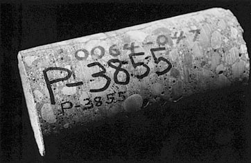
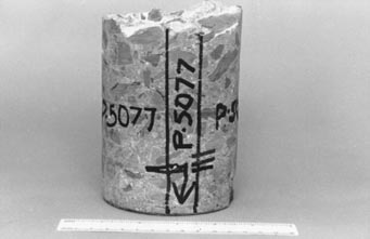
Petrography specimen numbers are preceded with a P, e.g., P-1222.
The appropriate petrography number (including the P) is clearly marked on each
specimen with a felt marker and graphite (see Fig. 3-1). Such numbers are called
P-numbers. The use of P-numbers is the major method of tracking specimens and
facilitating the location of data when questions concerning a specimen are received.
The number is
| Figure 3-1 CORE WITH P-NUMBER. The original construction number is not obscured, and the P-number is marked with a felt marker and graphite. |
included on all correspondence so that recipients of the correspondence may use the number for making inquiries concerning the specimen.
| CAUTION: Many ordinary inks begin to fade after they have been in contact with HCC paste for a few days. |
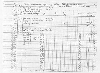
In the petrographic laboratories of VTRC, the most useful documentation of the receipt of a specimen was found to be a chronological log of all specimens entering the system (see Fig. 3-2). It is often used long after the original investigation has been concluded to discover when and how many specimens were submitted from a placement, what examinations were performed, where the specimens are currently, and how the data can be found. The logbook stays in one place and thus can be easily found. The log provides a guide to all the information available concerning a specimen from any source.
Entering the initial data must be easy and not very time-consuming. In its simplest form, the log might merely record the date, any specimen identification marking received on or with the specimen, the type of specimen received, the file number under which correspondence will be stored, and, most important, the petrography in-house specimen number. Indicate the general size of the specimen and whether the material (1) was cored with a diamond core drill from a hardened concrete placement; (2) was cast in a cylinder when the concrete was placed; (3) was produced in the laboratory or field as a cylinder, beam, or bar; (4) was found as a fragment; or (5) is a fragment that was sawed or hammered from a placement. Information that cannot be derived from the specimen should be available in the original documentation. In addition, the logbook can be used to record the progress of the investigation, tests performed, and disposal of the specimen or portions of the specimen.
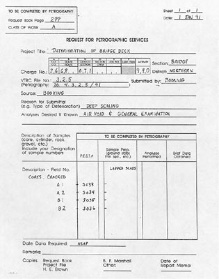
5. Fill out a "request for petrographic services" form. The form used by VTRC (see Fig. 3-3) has been changed many times, but it now seems quite adequate.
If the client is a person who is nearby (in the building), he or she should fill out the request form; otherwise, a petrographer should fill it out after the specimen is logged. The form should provide places for the project name, dates, charge numbers, file numbers, the source of the specimen, a brief description of the specimen, requested examinations, instructions to technicians, P-numbers, and the client's original numbers. Place the original of this request form with any other documents associated with the specimen. Send a copy to the client to notify him or her of the P-numbers assigned and that the specimen is in the system. Include a copy of the request form with the specimen as it is moved from office to preparation room and then to examination rooms for the microscopical procedures.
| Figure 3-3 VTRC REQUEST FOR PETROGRAPHIC SERVICES FORM |
The first laboratory notes on the specimen are written during the initial examination. The specimen as received may be large, but do not cut it to size until a complete plan of specimen examination has been drawn up. Use a hand lens or magnifying glass for examination until a reduction in size is a scheduled part of the plan. These preliminary notes and the client's request provide the direction for the plan of petrographic analysis.
The initial examination is accomplished in six steps, as listed in Table 3-4.
Table 3-4
PROCEDURE-INITIAL EXAMINATION OF SPECIMEN
1. Note and describe any cracks.
2. Note the location and condition of metal or any other material purposely included in the HCC.
3. Note the condition of the wearing surface.
4. Note the condition of the paste, any reaction products, the general size and distribution of the aggregate and air voids, and any other unusual features.
5. Photograph the specimen.
1. Note and describe any cracks. Pay particular attention to cracks that are on surfaces that were visible before the specimen was removed from the placement; these cracks were the ones first noticed by the client and are probably the ones that occasioned the submittal to the petrographic laboratory. If it appears that cracks on the top of the specimen may be part of a system of cracking and the client has not indicated the extent of this system, contact the client and make arrangements to obtain further information in the form of both verbal description and photographs or by personal visit to the placement.
Become familiar with the material in Chapters 4 and 10 50 that you can recognize cracks due to plastic shrinkage, alkali-aggregate reactions, and lack of an air-void system that can provide protection from freezing and thawing. Take precautions to preserve the evidence of these forms of deterioration.
Cracking that appears due to plastic shrinkage (see Chapter 4) is often cause for legal action and must be thoroughly investigated and photographed before any further procedures are performed on the specimen. Cracking that is due to insufficient protection by an air-void system may be cause for litigation if it occurred while the contractor could be held responsible.
Cracking that appears due to alkali-aggregate reactions will usually not be cause for legal action unless the materials used were not those specified. It is probable that the client will want a complete description of the aggregates, the reaction, the reaction products, and how the reaction affects the concrete. Contact the client by telephone, and inquire concerning the required breadth of the petrographic investigation. The study of thin sections, photographs, and photomicrographs may be requested. The client will probably desire sufficient information so that the reaction can be avoided in future concretes.
If the specimen is a cylinder and shows cracks, poor consolidation, or other signs of mishandling (improper storage or fabrication or both) and the client's request concerns low strength, it is possible that the cylinder tested showed low strength because it was flawed. Contact the client, and suggest compressive strength testing of specimens cored from the placement. If petrographic examination is required for other reasons, request replacement specimens (preferably cores). If replacement specimens are not available, try to avoid the flaws when planning the specimen preparation and make sure that the final report describes the condition of the cylinder and mentions the fact that the data obtained were not from the entire specimen.
In the case of a core or other specimen obtained from a hardened placement, try to judge which cracks are indigenous to the concrete of the placement and which cracks can be ignored because they were produced by the sampling procedures employed. Cracks produced by sampling procedures will usually appear fresh and contain no reaction products, but these criteria alone do not mean that the cracks were caused by sampling. If reaction products are present m the cracks or road dirt (dirt not due to drilling the sample) is present in the vertical cracks, such features can be assumed to be indigenous.
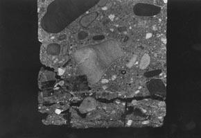
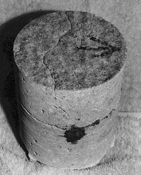
A system of cracks parallel to the wearing surface (called scaling), especially if the cracks become wider spaced with distance from the exposed surface, is probably due to freezing and thawing of saturated concrete unprotected by a proper air-void system (see Fig. 3-4). The most important determination to be made on such concrete is an analysis of the air-void system.
Systems of vertical cracks visible on the surface and most closely
spaced at joints and pavement edges are called D-cracking. In the midwest, such
cracks are usually due to the deterioration of certain impure dolomitic aggregates
under the conditions of freezing and thawing (Schwartz, 1987). In the northeast,
such crack patterns
| >Figure 3-4 SCALING CAUSED BY FREEZING AND THAWING. Occurred in concrete unprotected by proper air entrainment. To photograph the cracking, the specimen was glued back together with a dark glue and then cut vertically across the layere>d> > cracking. |
have usually been attributed to deterioration of the concrete paste due to the lack of an air-void system capable of providing protection from freezing and thawing (Andrews, 1953). When D-cracking is present, both the aggregate and the air-void parameters should be determined. D-cracking has not been found in Virginia.
2. Note the location and condition of metal or any other material purposely included in the HCC. If the material is not part of a commonly used reinforcement system, contact the client to inquire as to its origin.
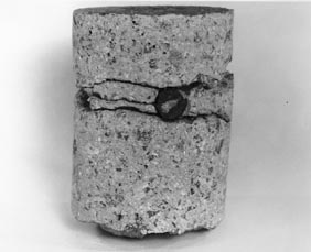
Notice whether the location of any of the surface cracking is related to the reinforcement (Figs. 3-5 and 3-6). Note the placement and condition of any reinforcing steel. Check for corrosion products near the steel and any associated cracking. If there is a system of cracks on the concrete surface that appear to lie directly over the reinforcement, this cracking may be due to corrosion of the steel.
Note horizontal cracks on the specimens. Note the depth of occurrence of these cracks. Often, there will be delaminations at the level of the top steel.
The thickness of concrete over the reinforcement necessary to provide protection from the corrosive effects of atmospheric gases with various types of concrete is detailed by Cady (1978).
Examine the bond between the paste and any other materials (such as reinforcement or anchoring pins) that are purposely present. Usually, the bond should be tight and strong and leave no space for the migration of fluids, wobble, or abrasive wear between the concrete and the other material (Lutz, 1978).
Aluminum, zinc, glass, and many plastics may be used in HCC as
connectors or electrical conduit. These materials are subject to corrosion when
enclosed in HCC
| Figure 3-5 CRACKING ON SURFACE AND SIDE OF CORE. With associated corrosion and expansion of the reinforcing bar. |
| Figure 3-6 DELAMINATION AROUND REINFORCING BARS. There is no cracking on the surface. |
3. If a finished roadway surface (wearing surface) is present on the specimen, note the condition of the texture of the surface. If the surface appears unusual or unable to provide skid resistance, consider the age, amount of traffic suffered by the roadway, original specified texture, and weather during placement. Unless these data are already available, obtain information concerning these factors from the client. Consider preparing a thin section (see 5.3.3).
4. Note all unusual conditions insofar as is possible without the use of a microscope and with no preparation of the specimens (occasionally, washing and partial-to-thorough drying may be necessary). If the client has submitted more than one specimen, be specific and note on which specimen the feature occurs.
Unusual conditions include, but are not limited to, the following:
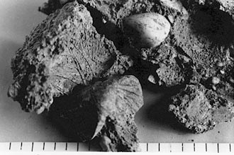
Casts of ice crystals are evidence of early freezing. If the concrete is fragmented and casts of ice crystals are abundant on almost all of the fragments (as seen in Fig. 3-7), the concrete was forced apart by the expansion of the ice formed before the paste achieved final setting.
Ice crystal patterns, such as "jack frost" patterns, may be visible on the molded surface of cylinders. Take these patterns at face value; the cylinders were subjected to freezing temperatures, but the patterns do not provide any evidence that the placed concrete was likewise frozen. Obtain a temperature history of the placed concrete and the cylinder concrete from the client before making any conclusions regarding these ice crystal molds. If the cylinders were treated as was the placed concrete, examine them for evidence of curing procedures and molds of ice crystals that may occur in freezing temperatures in fresh, improperly protected concrete (Rhodes, 1978).
| Figure 3-7 FRAGMENTS OF CONCRETE DESTROYED BY FREEZING BEFORE FINAL SETTING. The scale is in intervals of 1/8 in. |
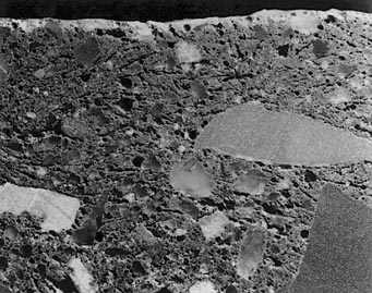
| Figure 3-8 SURFACE SAWED THROUGH CONCRETE SLAB THAT FROZE BEFORE FINAL SETTING. The blades of ice were, in general, parallel with the surface, and their orientation can be easily seen. The molds of the ice crystals are now empty and create zones of weakness throughout the concrete. About 3X. |
A surface layer of concrete in which molds of ice crystals are prevalent (see Fig. 3-8)indicates that the immature concrete was subjected to extremely chilling conditions (cooled below freezing, often with a wind that removed the heat of hydration). The unhardened concrete can freeze to a depth of several inches and develop casts of the ice crystals, which become zones of weakness and channelways for solutions.
5. Photograph the specimen with a scale and identifying P-number labels. This step may be omitted if previous photographs of the specimen have recorded all visible features that caused concern to the client, the important features, and any differences among a suite of specimens submitted as one sample.
If the initial observations seem to answer the client's questions completely, contact the client and ask if he or she wishes the investigation to proceed further. If the client is satisfied with the data already obtained, prepare all necessary written replies, permanent documentation, and the files as described in 3.5.
3.4 PRELIMINARY PLAN OF ANALYSIS
Preparing a plan to analyze the specimen may be accomplished in four steps, as indicated in Table 3-5.
1. Develop a plan for analysis that will answer the client's questions, explain unusual features, be performed within the specified time frame, and
Table 3-5
PROCEDURE-PRELIMINARY PLAN OF ANALYSIS OF SPECIMEN
Table 3-6
SAMPLE OF TYPICAL ANALYSIS
Specimens: Three cores 4 in. in diameter and 5 in. in depth.
Preliminary examination: A visual estimate of the air-void content indicates that two of the three specimens have areas of abnormally high air-void content and there are patches of paste that are low in aggregate.
Telephone report: The low strength is probably due to a high void content. The patchy nature of the concrete may indicate retempering.
Further client request: Conduct an analysis of the air-void parameters, and complete a megascopic and stereomicroscopic petrographic examination.
Plan of analysis:
1. Prepare vertical, finely lapped slices from each specimen.
2. Conduct a brief stereomicroscopic examination of the slices to confirm the original estimate of a high void content in two specimens and a normal content in the other. Consider if it is necessary to have additional slices prepared in order to represent the specimens properly.
3. Conduct an analysis of the air-void parameters of each type of specimen.
4. Conduct a detailed stereomicroscopic examination of each specimen slice to locate all features that might contribute to low strength and especially to search for any features that might indicate retempering.
5. Obtain photographs of the slices.
6. Prepare notes for the report, and report brief results to the client by telephone. Briefly record the results in the logbook. Record the data necessary to relocate negatives and proofs (see 3.5.1).
7. Prepare a memorandum, letter, or whatever is required as a formal report to this particular class of client.
Table 3-7
SAMPLE OF TYPICAL ANALYSIS
Client's request: Examine the specimens fabricated and tested in the VTRC concrete laboratory to determine if the differences in dynamic modulus can be explained by visual evidence.
Specimens: Two beams 3 by 4 by 16 in. prepared for testing in accordance with ASTM C 666. They were subjected to identical treatment, but an experimental chemical admixture was used in one beam. The concrete containing the admixture had a low dynamic modulus after the test.
Preliminary examination: Conduct a cursory examination of the exterior of the beams.
Plan of analysis:
1. Prepare finely lapped slices from the interior of each specimen. Obtain a sufficient slice from each specimen to satisfy the area requirements specified in ASTM C 457.
2. Conduct a visual examination (without any marking of the slices) of each finely lapped slice to survey the deterioration and plan further action in view of the following: aggregates, cement remnants, etc. appear identical; abundant microcracks are noted in both specimens. No comparison between intensity of cracking is usually available at this stage of the investigation.
3. Conduct an analysis of the air-void parameters of each specimen, and report the results to the client by telephone.
4. Obtain photographs of each slice. Record the roll and frame or file numbers of the negatives and proofs.
5. On each specimen slice, using a tape, mark off test areas of similar size and with a similar amount of paste.
6. Conduct a detailed stereomicroscopic examination of and mark in ink all microcracks within the marked test areas and other features (such as reaction products) detectable on the slices.
7. Obtain photographs of each marked slice. Record the roll and frame or file numbers of negatives and proofs.
8. Make a visual megascopic assessment of the comparison between the interior damage in the two specimens.
9. Prepare notes for the report.
10. Oral report: Present the marked slices or photographs to the client with the assessment. Suggest having a technician count the cracks on a series of traverse lines across the slices or the pictures.
11. Written report: Produce a written record of the examination. If the client requires no record other than the pictures, briefly record the results in the logbook and make note of the data necessary to relocate the photographs and negatives (see 3.5.1).
2. With a felt marker, mark the first planes to be cut with the diamond-edged saw with full consideration of the need for a detailed examination of the various crack patterns (see Chapter 4) and the likelihood of the need for an analysis of the air-void system. If the cutting plan is complex or if certain determinations must be made before the sawing is complete, it may not be possible to mark the cutting lines for all the planes.
A slice approximately 7/8 in. in thickness is generally required
for air-void determinations and general petrographic examinations. This thickness
generally yields a slice that is strong enough to withstand normal laboratory
wear and handling but is thin enough to permit a comfortably seated microscopist
to focus the microscope
Client's request: Determine the seriousness of the damage to the concrete caused by a driving rainstorm during placement. A prompt reply is requested.
Specimen: One core 4 in. in diameter, 3 in. in depth.
Preliminary examination of top and sides of core: Visual estimate of depth of damage.
Telephone call by petrographer to client: How much pavement area looks just like the surface of the specimen sent to us? How many intermediate types of surface are there? If the area is extensive and the damage looks serious, send a sketch with the dimensions of the areas involved and a core specimen of each of the different portions of the placement affected by the rainstorm. Send pictures if possible. [Client sent three additional specimens of the surface and sketches.]
Further client request: Detailed comments concerning damaged area and durability prognosis.
Plan of analysis:
1. Prepare vertical, finely lapped slices on which to examine the depth and nature of any distress.
2. Describe the distressed concrete, and measure the depth of the distress in each type of area. Include the condition of texturing, description of any color change between the surface layer and interior of the concrete, any cracking in the affected area, description of the air-void system near the surface (the surface layer is usually too narrow to permit a full air-void determination), and comments on the water-cement ratio near the surface.
3. Obtain photographs of the surface textures (particularly in cross section) showing the depth of any discoloration, layer of excess voids, or other indicator of condition. Record the roll and frame or file numbers of the negatives and proofs.
4. Compose a report including an estimate for each definable area of the depth to which the concrete will quickly wear away or how much concrete should be removed or textured to restore usefulness. If the damage is very slight, so state. Include photographs that illustrate the reasons for the conclusions.
easily without stretching the neck or cramming his or her knees into the table
or bench.
If the HCC is badly deteriorated, has an extremely high air content, or is otherwise fragile, it may be necessary to use a somewhat thicker slice so that the integrity of the slice will be preserved during subsequent handling. In cases where one or two major cracks exist in the specimen in the area to be sliced and the specimen has fallen apart or is about to fall apart, a strong epoxy may be used to keep the specimen together. Take care to prevent the epoxy from being squeezed or dripped into areas where it might obscure important features.
It is often necessary to reconstruct the specimen after cutting; therefore, place marks across all cutting planes (see Fig. 3-9). These marks are called match marks. Match marks should be unique to the cutting plane; one mark for the first plane, two marks for the second, etc. Take care to avoid marking any surface that will be subjected to any form of analysis. Most inks, from pens and markers alike, can sink deeply into porous concrete and will probably not be completely removed by lapping procedures. Ink marks can cause erroneous identification of aggregates and crack features and make the visualization of the paste features difficult.
Plan to cut across (at approximate right angles) any major cracks
observed. Lapped surfaces produced on these cuts will enable better observation
of the crack pattern.
The surface produced should allow the petrographer to see into cracks from the finely lapped surface.
Most commonly, surfaces are prepared by the technician cutting the material in a direction approximately perpendicular to a formed or finished surface of the HCC, and preferably across the layers in which the HCC was placed, thus producing a slice from the center of the material to be examined. This method is good when the size of the section produced does not exceed the capacity of the lapping equipment available or there are no obvious differences to be seen between the top and the bottom of the cores and the bottom portion can be ignored.
On occasion, it may be necessary to determine the differences between the individual air-void systems at various depths. When this is the case, the cutting plan will include taking horizontal slices at various depths and preparing each slice individually. Often, facing surfaces separated by only the thickness of the saw cut are considered as one specimen.
When the full depth of a core must be examined and the length of the core exceeds the size capacity of the lapping equipment, it may be necessary to saw the core horizontally into two or more pieces before preparing the slices to be surfaced.
3. Photograph the marked specimens (see Fig. 3-9).
4. Prepare and file documentation explaining the plan for
analysis. In any document produced concerning the specimen, report the
cutting plan used and explain it. Protect yourself in case any litigation
should ensue by always reserving some portion of each of the significant parts
of the specimen for at least 5 years.
Longer storage is recommended if possible.
3.5 FILING OF APPROPRIATE DOCUMENTS
Keep a permanent file in the petrography laboratory for each specimen that enters the system, even if the client's questions have been answered. In the file, place copies of all the original documents, notes on any oral communications with the client, the updated request sheet, laboratory notes, printouts of results of tests, and copies of all correspondence. Correspondence will probably be filed by clerks or secretaries in a more formal filing system, but that system may not have as much accessory data as does the file in the petrography laboratory. Keep a record of all testing procedures, such as air-void determinations. Such files are probably best organized by P-number and may be kept in the laboratory where the test is performed.
If photographing of specimens is performed in the petrographic laboratory, keep the negatives and prints in the permanent file for the specimen. If the photography is performed by another division of the organization that has possession of all negatives, place a record of how the negative is filed and the location of any prints in the file.
3.5.2 Temporary and Archive Files
Keep a temporary file of request sheets of work in progress. As a job is completed, update a copy of the pertinent request form and move it to an archive file. This archive file will be useful when a question comes in concerning an old specimen and the date and P-number are unknown.