U.S. Department of Transportation
Federal Highway Administration
1200 New Jersey Avenue, SE
Washington, DC 20590
202-366-4000
Federal Highway Administration Research and Technology
Coordinating, Developing, and Delivering Highway Transportation Innovations
 |
| This report is an archived publication and may contain dated technical, contact, and link information |
|
Federal Highway Administration > Publications > Research > Structures > Covered Bridge Manual |
Publication Number: FHWA-HRT-04-098 |
Previous | Table of Contents | Next
The floor system of a covered bridge is an important element of the bridge, because it supports the loads and transfers them to the trusses. To keep the relationship of floor and trusses in perspective, it is helpful to understand that designers prefer the floor to have somewhat less capacity than the trusses. The trusses are designed with more capacity than the floor so that, in case of an expected overload, the floor will be the first to exhibit distress, avoiding a major failure.
This chapter presents information about the following parts of the timber floor system:
It is extremely rare to find a floor system in an historic covered bridge that is still intact from the time of its original construction. At a minimum, the decking is likely to have been replaced several times. Often, the stringers and/or floor beams also will have been replaced. Accordingly, this chapter deals with the various floor conditions and components that are currently found in those bridges. It also presents a number of examples of how floor components are replaced in covered bridge rehabilitation projects.
Figures 40 and 41 depict two of the most common conventional floor systems. Figure 40 represents the basic floor system, a type most routinely found in Town lattice truss bridges. This floor system comprises transverse floor beams and longitudinal decking. Figure 41 represents the more complicated floor system, typically used in queenpost truss bridges, or more generically, all other truss types which have more distinct, separated panel points (unlike the uniform construction of the Town lattice truss). This system results in fewer, but heavier, transverse floor beams. An added element in this system is the longitudinal stringer that supports the transverse decking. The following sections discuss these individual components in more detail. The bulk of this chapter is devoted to the conventional timber floor components. The final subsection discusses some of the various replacement floor systems that have been installed in covered bridges.
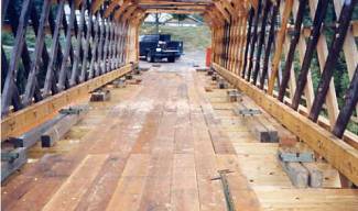
Figure 40. Transverse floor beams and longitudinal decking—Fitch's Bridge, Delaware County, NY.
Figure 41 depicts the three-layer floor system of floor beam, longitudinal stringer, and transverse deck (out of view). The extension of the floor beam beyond the face of the outside siding covering of the Pony truss normally supports a strut between the end of the floor beam and the top of the truss to provide lateral support for the top of the truss. An alarming feature of this image is that the struts were temporarily removed to facilitate inspection of the bridge when this photograph was taken.
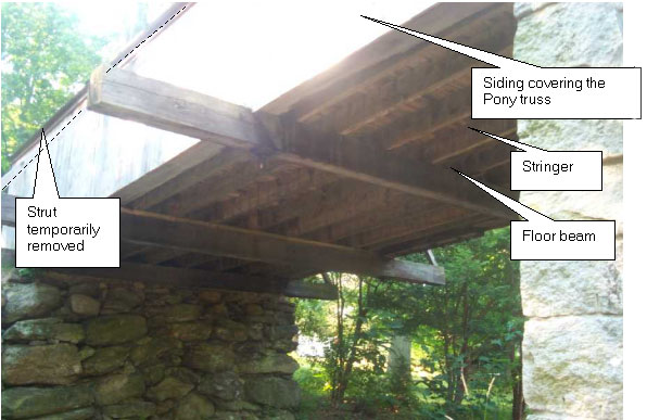
Figure 41. A floor with stringers, floor beams, and transverse decking—Comstock Bridge, East Hampton, CT.
Transverse floor beams are important members of any covered bridge floor system. As explained in chapter 2, these beams span between the two (or, rarely, three) longitudinal trusses. These beams provide the primary support for live loads by spanning between the trusses.
Floor beams are subject to two primary stresses: bending and shear. Stress bending is experienced as the beam is loaded. The top fibers of the member are compressed, tending to shorten the top of the beam. The bottom fibers in the member are pulled apart in tension, tending to lengthen the bottom of the beam. Bending stresses often control the design of floor beams made of steel and/or concrete. Timber is relatively strong in resisting bending stresses.
Bending stresses are at the highest near the center of the span of the floor beam, indicating the need for a full beam section there. Some floors contain a bottom lateral system with members that meet at midspan of a floor beam. Often, such connections involve a mortise and tenon arrangement that causes some section loss from the floor beam (see figure 42 for an example of a similar connection at the end of the floor beam). Although the mortise will be located near the neutral axis of the section, the reduced strength of the floor beam can be significant. (The neutral axis of an element is that geometric location within the section that experiences no stress from flexural loading of the section; e.g., for a rectangular element, it is usually located at midheight of the section.) Hence, careful consideration of this situation is advisable, and such details should be avoided, if possible.
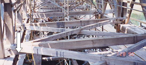
Figure 42. Mortise-and-tenon connection in floor beam—Downsville Bridge, Delaware County, NY.
Although there may also be a connection of the laterals nearer the end of the floor beam (as shown in figure 42), or substantial reduction of section due to the notching of the end of the floor beam, the flexural stresses in the floor beam are usually quite small at the ends. These conditions rarely control the sizing of the floor beam, but should be checked.
The second primary stress type to consider in floor beams is shear. One way to visualize shear stresses relates to the tendency for individual elements within the beam to distort from their originally square shape to parallelogram (but nonsquare) shapes (technically a rhomboid). This type of distortion is termed shear distortion.
Timber is an orthotropic material; its basic properties vary in relationship to the wood grain direction. In timber, the vertical shear resistance (across the grain of the member) is strong and rarely controls the sizing of the member. However, horizontal shear resistance (along the grain of the member) is relatively weak. It is this along-the-grain shear stress that is tabulated in the allowable stress tables of the NDS. The horizontal shear stress term is used in timber references, because shear forces (and their attendant shear stresses) are generally larger in beams than in columns. The weaker along-the-grain shear component is oriented horizontally in beams designed to resist vertical gravity loads. Shear stresses often control the size of the floor beams. Unlike flexure, which results in the highest bending stresses at the middle of the floor beam, shear stresses are largest near the end of the beam.
Local horizontal shear stresses in a timber beam increase where there is any cross-sectional defect. These defects could be natural, such as shrinkage checks resulting from the normal drying of the wood, or a knot. The defect could also result from the connection details used with the member, such as a notch cut to fit a floor beam into its support location along the truss. Figure 43 depicts the detail used at the ends of most floor beams in Town lattice trusses. Note that both the bottoms and tops are notched. The bottom notch provides a transverse and positive stop against the truss chord. The top is notched to allow the member to fit into the smaller and sloped top openings among the lattice truss members. The combination of these notches can increase the shear stresses in the floor beam sufficiently to require reinforcing the beam at its ends. This is commonly accomplished with vertical, large-diameter lag screws. This method of member reinforcement is not currently included in design specifications; however, the article, "Design of Notched Wood Beams" in the Journal of Structural Engineering discuss these issues.[7]
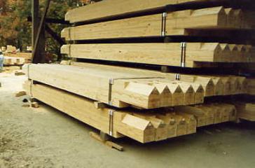
Figure 43. End notches of floor beams used in a Town lattice truss—West Dummerston Bridge, VT.
Recently there has been some interest in using hardwood timber dowels as a substitute for the lag screw in reinforcing the critical shear planes in the floor beams. The lags tend to rust (even if originally galvanized), thereby becoming both unsightly and less effective. A hardwood dowel can also be less expensive than a galvanized lag screw. Wooden dowels are not mentioned in current design specifications, but various researchers are starting to discuss dowel behavior. Several bridge engineers have used dowels in lieu of lag screws in a few installations where there was confidence that the timber dowel could provide the improvement in shear resistance that analysis indicated to be necessary. Figure 44 depicts use of timber dowel reinforcement of a post against horizontal shear from the vertical component of load in the diagonal. The darker colored chord is pressure treated, while the lighter colored post and diagonal are not. Similar dowel reinforcement of the floor beam is possible. The truss is shown horizontal in this image as it was being constructed on falsework.
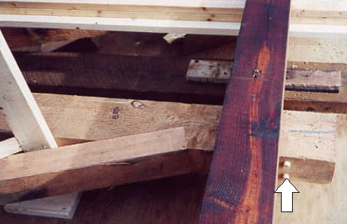
Figure 44. Timber dowel reinforcement of post—Mill Bridge, Tunbridge, VT.
Vertical deflections also deserve investigation when considering floor beams. A floor beam adequate to withstand the bending and shear stresses associated with passage of a vehicle could still deflect enough to be noticed by the bridge user. Most design specifications limit the amount of deflection that is permitted in members—for instance, AASHTO specifications indicate a live load deflection limitation of span length (in inches) divided by 500 for timber elements. This deflection limitation can, in some instances, establish that the floor beams should be larger than would be required to resist the shear and bending stresses. In practice, floor beams of covered bridges are often too flexible to satisfy this requirement. Therefore, one must decide if such a serviceability limitation is reasonable or if the limitation can be relaxed. Several practitioners have accepted such a relaxation, but the degree of such acceptance is not known.
Somewhat separate from the discussion of the general issues related to floor beams, this section of the manual raises a related topic. That is, evaluation of covered bridges often finds the floor system to be substantially weaker than desired, when compared to current requirements. Many believe that the current specifications are unduly harsh when evaluating the strength of floor beams. This conclusion comes from the fact that a floor beam found to be theoretically weaker than desired often may be functioning successfully, without evidence of distress. Some say that the allowable stresses for shear are too conservative. Others suspect that the load distribution factors for these types of floor systems are too conservative. To date, there is no commonly accepted engineering analysis or practice related to this topic, although many people are pursuing it. Much more research is warranted.
Therefore, if one subscribes to such a belief and resists accepting the verdict of the analysis as taken directly from applying today's specifications, then there must be a consideration of alternative means of assessing the strength and serviceability of the floor beams. This point is reinforced every time recommendations are made to replace seemingly sound and satisfactory existing floor beams.
Many extant floor systems contain structural elements not part of the original construction. These elements are aligned along the axis of the bridge and are attached to the underside of the floor beams. They typically include a single line of elements along the center of the floor; sometimes there are twin lines along the third points of the floor beams. The members are usually solid sawn timbers and are arranged in a staggered fashion along the bridge with each component continuous under many floor beams.
These elements are identified by a number of terms; a common term is distribution beam. The name derives from the intent of the element to distribute the effect of a wheel load to more than one floor beam. "Distribution Beams" in chapter 12 discusses the analytical issues involved; their effectiveness is debatable. Figure 45 shows an example of a twin line of distribution beams.
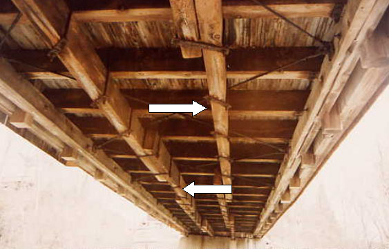
Figure 45. Installation of distribution beams—Union Village Bridge, VT.
The connection to the underside of the floor beam is almost always via steel U-bolts positioned over the top of the floor beam and clamped under the distribution beam, with a steel plate at the downward end of the U-bolt. When a vehicle crosses a floor beam, its deflection forces the distribution beam downward, thereby pulling down on adjacent floor beams; this is why it is called a distribution beam.
In practice, the connections can loosen over time (even if only from shrinking timbers), and the deflection of the distribution beam may become so small as to make its contribution to a particular floor beam suspect.
These beams are often quite stout—up to 203 mm thick by 406 mm high (8 by 16 inches). Therefore, they can add considerable weight to the bridge.
Some engineers believe that these distribution beams are clear evidence that bridge specifications underestimate the capacity of the floor beams. Adding distribution beams is simply intended as a means to increase the distribution of vehicular loads to more members. Yet, comparing the conditions of floor beams in scores of historic covered bridges does not demonstrate improved conditions of the floor beams in those bridges with distribution beams than in those bridges without them.
A study of these components was undertaken as part of the statewide study of Vermont covered bridges during the early 1990s. The conclusion of the study was that the contribution of the components could not be assured; therefore, no benefit from them should be assumed. Further, when work on a particular bridge with distribution beams was undertaken, it was recommended that the beams be removed to lighten the load on the bridge.
There are several other topics of common interest regarding floor beams.
Floor beams play a vital role in helping the bottom of the bridge resist lateral loading from wind or stream forces. For bridges with intermediate connections to lower laterals in the middle of the floor beams, larger forces can be imparted to the floor beams from such lateral loading, causing transverse (weak axis) bending of the floor beam.
Similarly, traction forces in the deck system (from the braking of vehicles) can also cause additional stresses in the floor beam.
Occasionally, the ends of floor beams have an inadequate bearing area that can lead to crushing of the floor beam. This may be especially relevant to Town lattice truss floor systems for those floor beams that are supported only by the innermost chords.
Typical floor beams range between 203 to 254 mm (8 to 10 inches) wide and 305 to 356 mm (12 to 14 inches) deep. Some narrow Town lattice bridges, with their multiple floor beams, contained much narrower floor beams to support the originally lighter vehicles. In bridges that require sufficient capacity for heavier vehicles (18 metric tons (MT) or 20 tons), or those that are two lanes wide, reasonably sized solid-sawn members may not be strong enough. In these cases, floor beams made from laminations of dimensional lumber glued together (glue-laminated, or "glulam" beams) can provide more capacity through increased allowable stresses and larger sections.
As explained above, some covered bridges have stringers—longitudinal beams supporting load from the decking to the floor beams. The stringers are usually spaced no more than 0.6 to 1.2 m (2 to 4 ft) on center. Stringers only span from one floor beam to the next, with the span limited to 2.4 to 3.7 m (8 to 12 ft). Sometimes, the stringers are long enough to span across two bays of floor beams, making them two-span continuous members. These members are more stiff than simple spans (when the same size as single span elements), and do a better job of distributing live load deflections, particularly when the two-span stringers are staggered with the ends supported by alternating floor beams.
Like floor beams, stringers are sized to resist flexural and shear stresses, and to limit deflection. Shear stresses often control the size of stringers. Member sizes of up to 254 to 305 mm (10 to 12 inches) deep and 100 to 150 mm (4 to 6 inches) wide are common. Stringers are usually single component, solid-sawn timbers.
An issue common to all timber decking in a covered bridge is the lack of friction of the road surface. The deck surface inside a covered bridge often becomes slick, and it is common to experience sliding inside of a covered bridge when applying the brakes. There is no commonly accepted practice to combat this phenomenon, yet it is an important issue to recognize. Some choose to install railing constrictions to force slow passage of vehicles in light of this issue. In rare instances, an asphalt-wearing surface is used above the decking for this purpose.
The simplest and most common deck type uses heavy, solid timber planks. They directly support the wheel loads, and distribute them to the stringers or floor beams. In stringer floors, the deck planks run transverse to the bridge. In bridges with floor beams only, the planks span longitudinally. Planking is routinely 75 or 100 mm (3 or 4 inches) thick, and can be 152 to 305 mm (6 to 12 inches) wide, and up to 3.7 to 4.9 m (12 to 16 ft) long. Deck planks are usually cut from softwoods, like Southern Pine or Douglas Fir. The added dead load applied with denser hardwood planks is rarely justified by load requirements. Planks are usually simply spiked or screwed to the supporting members. Typical transverse plank decking is shown in figure 46. This instance has longitudinal running planks on top along the wheel lines.
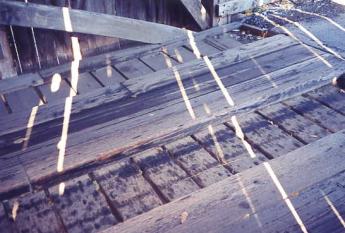
Figure 46. Typical transverse plank decking with running planks—Salisbury Center Bridge, Herkimer County, NY.
Some covered bridges have two layers of timber planks, laid at right angles. This is difficult to justify, either economically or from the standpoint of load capacity. There are even examples of bridges with a double layer of deck planks, and a third layer—running planks—on top of those two layers (see "Running Planks" later in this chapter).
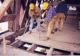
Figure 47. Nail-laminated decking being removed—Fitch's Bridge, Delaware County, NY.
Nail-laminated decking is usually assembled with pressure-treated lumber, to help protect against early deterioration. Structural grade material (select structural, or No. 1 grade) can provide the strength necessary to properly support design vehicles. Southern Pine is a popular species for this use.
An alternative to the nail-laminated decking is to use deck panels glue-laminated in shops, from 50-mm (2-inch) nominal lumber. These panels are often about 1.2 m (4 ft) wide and may be up to 4.9 to 6.1 m (16 to 20 ft) long. The panel depth is the same nominal 100, 150, 200, or 250 mm (4, 6, 8, or 10 inches). This depth and the higher allowable stresses make these panels effective at carrying loads between widely spaced floor beams. These deck panels are, therefore, usually oriented longitudinally along the bridge. This means there are multiple panels across the width of the roadway. The panels are usually staggered so that the butt joints of adjacent panels are supported on different floor beams. Often, adjacent joints are specified to be at least 1.2 m (4 ft) apart along the axis of the bridge. Panels may be installed transversely over longitudinal stringers.
The panels are usually manufactured of treated lumber and milled on the top to provide a smooth surface. Adjacent and end-butted panels are often interconnected with blind steel dowels to share loads between panels and decrease differential displacements. Special hardware attachments connect the panels to the floor beams. The pressure treated lumber warrants specifying galvanized or even stainless steel panel connection hardware. Figure 48 shows glue-laminated floor beams and decking system under construction. These panels were fabricated in single units for the full length of the bridge—39.6 m (130 ft).
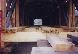
Figure 48. Glue-laminated floor beams and decking system under construction—Hamden Bridge, Delaware County, NY.
Traffic will gradually wear away the top surface of any decking. This wear can be significant, especially on softwood decking, so that it would all have to be replaced in a few years, even though the damage is fairly localized. A common practice is to lay down a layer of hardwood planks, aligned only along the wheel paths. These members are intentionally sacrificed to the wear and more readily replaced as necessary, without having to replace the entire deck. A typical installation of twin lines of running planks is shown in figure 49.
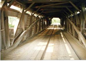
Figure 49. Running plank installation—Taftsville Bridge, VT.
Running planks may be positioned along the wheel paths in two separate runs, often 1 m (3 ft) wide, and made of multiple planks in each unit. Occasionally, the running planks are placed in a single full-width layer. The former scheme is less expensive, and tends to slow traffic by helping drivers avoid slipping off the running planks. The latter scheme, in contact, avoids the issue of vehicles slipping off the wheel tracks (which could cause the driver to lose control of the vehicle) and hitting the trusses. The tendency of twin pairs of running planks to slow down drivers is widely recognized as an effective tool to enforce a speed restriction on the one-lane bridge. For those bridges often used by snowmobiles, the issue of the width of snowmobile tracks and skis must be addressed and may lead to the decision to avoid using the central gap between wheel line strips. Similarly, those travelers using motorcycles must be careful due to slickness of the wood and the instability associated with the drop-off.
Running planks are usually 50-mm (2-inch) nominal thickness and may be treated with preservatives, if desired. Running planks often wear out long before untreated members would rot, indicating that treatment against decay may be an unnecessary expense. This decision should be based, in part, on the expected number of vehicle passages each day. Higher use will require member replacement more often, meaning pressure treatment is more extraneous. Low use might direct the prudent use of decay-resistant treatment.
Timber floor systems are fairly regularly replaced, due to deterioration, excessive wear, and/or structural distress after 30-40 years. Occasionally, an owner will install a different floor system than the one originally installed in the bridge. The owner may find that an alternative is apparently less expensive or may provide more capacity than the previous floor system provided. In fact, the floor systems are often the weak link in the bridge's load capacity. This may not be all bad; an overly heavy load might fail some floor components without dropping a vehicle in the river, or without taking the entire span with it. Heavier nail-laminated or glue-laminated decks are generally installed to upgrade the load-carrying capacity from that of the original timber plank deck. Usually, this does not have a significant aesthetic effect on the structure.
In some instances, a deck is replaced in the course of installing a structurally independent bridge system within the shell of the original covered bridge. This can be accomplished by installing two or more steel beams within but below the original trusses with a timber, or even a concrete deck, supported on the longitudinal steel beams. The beams would be supported on independent bearing areas at the abutment, separate from the truss support area. Sometimes the beams are deep enough to show below the bottom of the original trusses. This means that either the roadway surface must be raised to maintain the same low point of the structure elevation (important when the hydraulic opening must not be reduced), or the beams project below the trusses (when there is ample hydraulic opening). Often, the beams are not readily visible and are not objectionable to the traveling public. Many consider this action an effective gutting of the bridge and, therefore, unacceptable. However, it may be the only way to keep the bridge in service. Figure 50 depicts an independent floor system.
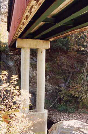
Figure 50. Independent floor system—Chiselville Bridge, VT. Note that the pier cap does not support the timber truss, which must still support the weight of the covering and snow.
Recent experience in Vermont indicates that this action would not be accepted in that State, while Pennsylvania continues to allow this reinforcement method. Each State and owner deals with this preservation issue according to local practices, customs, and resources.
This action, when completed, separates the timber trusses and covering from the support of vehicular loading. Hence, routine bridge inspections (mandated by the Federal Government every two years) will focus on the main supporting members (steel beams and decking) and may pay less attention to the trusses and covering. Eventually, serious deterioration may become more pronounced and avoid detection until collapse of the covering onto the beam bridge is imminent. This represents a significant safety concern for the users of the bridge and a potential loss of an historic bridge.
An important issue relates to the connection of the shell to stabilize the bottom chord of the truss. A horizontal connection of the bottom chord of the shell is required to provide resistance to wind loading against the sides of the shell. However, the independent structure will deflect vertically under the influence of vehicular traffic. The unconnected shell will not deflect from that live load. Conversely, the shell will deflect from the influence of snow loading while the independent structure does not. Hence, if one attempts to join the bottom of the shell to the independent structure, adequate vertical differential motion must be accommodated. Further, if this connection binds over time, it can pull the bottom chord of the shell apart and destroy the shell. Therefore, this requires extreme care in detailing the connection.

