U.S. Department of Transportation
Federal Highway Administration
1200 New Jersey Avenue, SE
Washington, DC 20590
202-366-4000
Federal Highway Administration Research and Technology
Coordinating, Developing, and Delivering Highway Transportation Innovations
 |
| This report is an archived publication and may contain dated technical, contact, and link information |
|
Federal Highway Administration > Publications > Research > Structures > Covered Bridge Manual |
Publication Number: FHWA-HRT-04-098 |
Previous | Table of Contents | Next
This chapter deals with several important bridge components, though these are ancillary to the main trusses and floor system. These ancillary features include:
It should be noted that there is no correct or recommended practice for many of these topics. Historic preservation issues prevent significant alterations from those of the original construction. For example, a bridge built with a flat roof and no portal extension would not be rebuilt with a gabled roof and portal extension. Accordingly, the discussion here aims to document engineering and construction issues related to an inherited feature. In instances where changes can be made—notably the railing system—recommendations—are offered.
Of all of the ancillary features of a covered bridge, the roof may be the most important, because it is the first line of defense against the detrimental affects of weather. Yet the complete system is quite involved, with many individual aspects deserving attention.
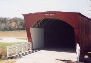
Covered bridges have diverse rooflines. By far, the most common roof style is the gable configuration (see figure 51). Yet, even in this simple form, the slope can vary from very nearly flat to quite steep. The side overhang can vary from short to moderate. In elevation view, the roof ends are usually cut at right angles to the axis of the bridge (or plumb), while a few extend to a point over the entrance of the bridge. Perhaps the most recognizable roof form is the flat-roofed bridge of film fame, from "The Bridges of Madison County." Figure 52 presents a flat roof bridge in Madison County, IA.
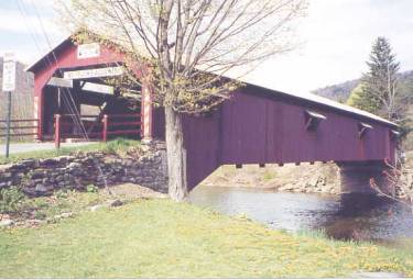
Figure 51. Classic gable roof—Forksville Bridge in Sullivan County, PA.
(photo courtesy of Abba Lichtenstein)
Figure 52. A flat roof bridge—Hogback Bridge, Madison County, IA.
The statewide Vermont study (noted earlier) identified the following distribution by material types:
This represents the largest survey of roofing materials on covered bridges in a large geographic area and is informative, although not necessarily indicative of other areas.
Preservationists tend to prefer wood shingles, because wood generally would have been used on the original construction. However, metal roofing can represent important advantages to the covered bridge engineer, because it tends both to reduce the dead load and to help shed snow loads much faster than any other material. As explained in chapter 11, snow loads often represent a significant load on a covered bridge. Avoiding large snow accumulations, especially asymmetrical snow drifts, helps to preserve bridges for longer periods with reduced major rehabilitation needs. For these reasons, it is recommended that metal roofing be used for replacements in areas of snow.
The roofing material typically is supported on roof boards that are, in turn, supported on rafters. As might be imagined, a very diverse assortment of roof boards (or nailers) has been installed on covered bridges by original builders and by all subsequent maintainers. Generally, however, one finds nominal 25-mm (1-inch)-thick boards that may be spaced either tightly or with gaps. Plywood sheathing is rarely used. In part, the roof board type and spacing depend on the type of roofing material (e.g., wood shingles require nailers that are more regularly spaced than metal roofing).
The rafter configurations on covered bridges are almost always similar. For the conventional gable roof, the rafters are invariably single pieces on each side of the ridge. Rafters vary in size, with the most common dimensions of 50 to 100 mm (2 to 4 inches) wide by 100 to 150 mm (4 to 6 inches) thick, and on-center spacing ranging from 610 to 915 mm (24 to 36 inches). Most rafters overhang the outside edge of the truss, anywhere up to 0.6 m (2 ft) on either side. The rafters are usually notched where they bear on the truss top chord ("bird's-mouth") and are toe-nailed to the truss.
The peak of the gable roof may have a ridge pole, a board or plank member that runs the length of the roof, at its peak. The rafters butt against it from either side. This ridgepole can be omitted, leaving the rafters butting against one another at the ridgeline.
The typical gabled roof slope varies, but is usually about a ratio of one unit vertical to two units horizontal, or 6 on 12. A steep roof would be 12 on 12; a so-called flat roof would be only 2 or 3 on 12.
Often, a horizontal member is attached between opposing rafters, at about their midheight from the truss top chord to the peak. These members are commonly called rafter ties, which imply that they are loaded principally in tension. Yet many builders install them to reduce the sag in otherwise undersized rafters, which would require their being loaded in compression and more properly called rafter struts. This basic misnomer is typical of the general confusion about how these members behave in roof structures. The basic axial load issue—tension or compression—is a direct function of the lateral restraint available at the rafter bird's-mouth connection. If the rafters are restrained laterally by firm connections to sufficiently rigid timbers, the rafter strut is in compression and reduces sag while increasing the outward thrust at the bird's mouth. If, on the other hand, the rafters are free to spread at the bird's-mouth connection, the collar tie is in tension and is responsible for holding the roof together. This is achieved at the cost of increased bending (and the attendant sag) in the rafters.
One underappreciated effect these members can have is in mitigating the impact of unbalanced snow loads. If a snowdrift builds on one side of the roof, then the rafter beneath it sags and pushes the opposite side of the roof, through the intervening rafter strut, in a way to help share the unbalanced load between the two rafters. Sometimes the ties are used on every rafter; other times they may not be present on all rafter pairs—perhaps on only every other or every third rafter.
Rafter ties certainly are not mandatory, and many roofs do not have them. It seems to be more a matter of individual preference on the part of the engineer or builder, yet the advantages of rafter ties outweigh their cost, and they are recommended. Figure 53 presents an example of rafter ties at midheight of the rafters. These are the horizontal members above the X upper laterals in the foreground.
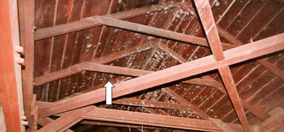
Figure 53. Example of rafter ties—Northfield Falls Bridge, VT.
It may seem odd that something so seemingly inconsequential and straightforward as a rafter can be such an analytical challenge to the covered bridge engineer. The rafter design strongly depends on its assumed span length. If the designer/analyst does not use rafter ties or struts, then it is fairly clear that the span of the rafter is between the support on the truss top and the peak. Yet, the analyst must be careful. The design is predicated on compatible loading and span length. If one uses the length along the slope of the roof, then one must use a load value that is at right angles to the rafter (or the component normal to the roof plane). If the analyst is using globally projected vertical loads, then the horizontal component of the length must be used to be compatible. A common mistake is to use globally projected vertical loads and span lengths measured along the rafter. While this is not compatible, it is fortunately conservative (i.e., this methodology leads to larger rafters being required or specified).
If the designer includes rafter ties, then is the rafter span only the longest of the two sections? On first inspection, this might seem to be so. Yet, the rafter tie (or strut) essentially converts the simple span behavior of two independent rafters on opposite sides of the roof into an interconnected unit that functions as a frame. Now, with the tie in place, snowdrifts can induce frame behavior, and the assumed support condition at the trusses becomes crucial. Does one assume that the trusses are fixed horizontally (in which case, the rafter frame is restrained against deflecting outward at the ends), or does one assume the trusses may spread apart under roof loading, so that the rafter ends are allowed to settle outward? In this latter case, the bending stresses in the bottom surface of the rafter frame would increase substantially.
Are rafter frames always restrained from horizontal motion at the truss tops? Yes, if a properly designed and detailed top chord horizontal bracing system exists, because the trusses are restrained at the point of connection of the bracing. Additional questions also arise: Can the trusses deflect outward between brace points? What bracing is both sufficiently stiff and strong to provide and to resist the horizontal support component?
These are interesting points for the engineer to ponder. Each situation is different and requires a site-specific evaluation according to the strength of the bracing system and lateral strength of the truss top chord. Therefore, the rafter analysis that at first seemed straightforward becomes a little more involved.
In general, it usually is sufficient to size rafters based on simple span behavior, regardless of whether or not a rafter tie is used. Attempting to analyze the rafter combination with tie or strut more accurately may even lead to erroneous results, if some of the more complex support issues cited above are mishandled.
Rafters should not be designed without considering these consequences. When replacing rafters, engineers should size them according to proper design techniques. However, historic preservation of rafters that may be in good condition otherwise, regardless of theoretical overstress, may be desired. This discussion highlights the various issues related to these elements.
The portal of a covered, or any other through bridge, is its entranceway or opening (or the end elevation view), comprised of the sides and roofing. Covered bridge builders have provided plain portals or more ornate portals with special architectural treatments and enhancements. An example of unusual detailing of a roof portal, finished more like a house than a bridge, is shown in figure 54.
In large part, the portal represents a nonstructural detail; the designer or builder may simply provide what the owner desires. Very few covered bridges have included especially stiff and strong lateral load bearing elements in the portal detailing. This is not a conservative method—how is the entire lateral load carried in the top chord lateral bracing finally transferred down to the abutments, if not through some particular portal bracing? The knee braces can transfer the loads down to the floor level bracing along the span. The flow of the lateral forces, applied to the upper half of the central zone of the span, usually is resisted by a complex combination of knee bracing and transverse bending in the truss elements down to the deck, and top chord bracing longitudinally to the ends.
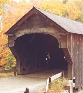
Figure 54. Unusual detailing of a
portal—Upper Falls Bridge, Weathersfield,
VT.
Some bridges contain a separate panel of structure before the beginning of the actual trusses. This feature is often termed a portal extension, or shelter panel. It helps protect the ends of the trusses from wind-blown rain. An example of a portal extension that protects the ends of the trusses from weather damage is shown in figure 55 (see also figures 14, 15, and 16).
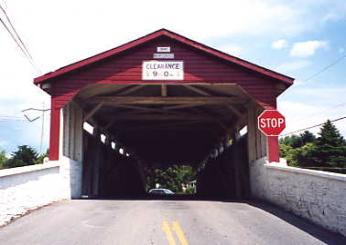
Figure 55. Example of portal extension—Wehr Bridge, Lehigh County, PA.
Covered bridge siding can be full height or only partial. Often, the siding is stopped well below the eaves to provide better ventilation through the bridge. This gap can also introduce natural lighting, at least during the day. Sometimes there is a larger gap at the top, such that the siding covers only the bottom portion of the trusses. In some cases, it may even be short enough to allow passing motorists to look over the top of the siding; such a bridge offers a continuous window to users, albeit with reduced weather protection.
The siding is usually rough-cut softwood, either painted, stained, or untreated. In these cases, the siding is installed vertically. Sometimes the siding also includes "battens" (narrow boards over the gaps of the main boards), but usually the gaps are left open.
More elaborate siding is installed on some covered bridges, either vertically or horizontally, in which case the siding is often painted. Rehabilitating bridges with special siding often requires that the siding be removed carefully so that it can be reinstalled and repainted.
Many bridges contain openings (windows) in the siding. The windows may be quite small or large, depending on the preference of the owner, designer, or builder. The windows provide additional light inside the bridge to facilitate safe daytime passage. They also often provide fishing access. At many bridges detailed without windows, vandals break boards to gain such fishing access. This behavior seems so widespread that wise detailers install windows when rehabilitating a bridge, even if it did not previously have them. While the windows expose surrounding timber to the effects of windborne rain, significant rotting of primary timbers around these windows is quite rare, provided good trim details are used (ones that foster rapid drainage and do not trap any water). Many bridges have windows only on one side.
At some bridges, the siding extends on the inside at the ends, for distances up to 3 m (10 ft). This internal siding is identified by various terms, as noted in chapter 2, but the most appropriate term is shelter panel. This siding protects the ends of the primary structural members from splashing water from vehicles and windborne rain. The inside siding can effectively protect the timbers, but it also makes it difficult to perform routine visual inspections in that portion of the structure. Further, the reduced ventilation around the truss members may actually accelerate rotting of the timbers.
There is some controversy regarding siding, from the perspective of historic preservation. Some believe it is very important to replace siding, when necessary, with virtually identical materials and details, including maintaining the same preservative treatment (paint, stain, or no treatment). Others believe that the siding is less significant from a preservation perspective, since it almost always has been replaced at least once during the life of an historic covered bridge.
Therefore, some choose to modify the siding details to provide improvements as deemed necessary during subsequent rehabilitation of the bridge. Such improvements might include better detailing around windows to reduce exposure of truss elements, or battens might be added where not used before the rehabilitation. Some also use 50-mm (2-inch)-thick siding specifically to lessen damage from vandals. Modern siding installations often rely on the use of stainless steel screws rather than smooth shank nails as an improved means of vandal protection.
Bracing is vital to the structural well-being of covered bridges (as with almost all structures). Chapter 2 introduced the various bracing components, in the nomenclature subsection. This subsection offers additional engineering information related to bracing.
Transverse tie beams connect the tops of the two longitudinal trusses. They are often larger sawn members, up to 200 to 300 mm (8 by 12 inches), to accommodate the joinery details with the lateral braces. The tie beams are anchored to the top of the trusses, often with vertical bolts. They are usually notched across the top chord to provide an additional and positive stop against transverse displacement at the top chords.
The lateral braces at the top chord level are usually at least 100- x 150-mm (4- x 6-inch) members and are usually joined to the transverse tie beams with mortise-and-tenon connections. Instead of being pegged, these connections are usually tightened with matched wedges to keep the system tight. This means that only those braces that are oriented to be loaded in compression will be working. The wedges cannot transfer any tension forces from the braces to the tie beams. Figure 56 depicts a typical connection of lateral braces (complete with painted markings from 1885 when this bridge was relocated to its current location) with the light-colored tie beam replacement. The light-colored matched wedges (shown transversely in this view) can be driven against each other to keep the system tight. At the intersection of the lateral X-braces, there may be a vertical bolt, and there might be a matching dado notch cut into both members, to ensure that they are flush and in plane. A common feature of lateral X-braces is that the end mortise-and-tenon connections are cut so that the lateral X-braces must be slightly bowed around one another, to fit into the connections. This bowing adds resistance to potential loosening of the laterals, by inducing some friction forces along the top and bottom surfaces of the joinery. The pretensioning also helps to prevent rattling overhead.
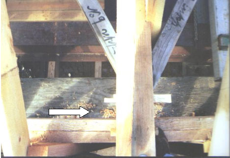
Figure 56. Lateral brace connection at tie beam—Fitch's Bridge, Delaware County, NY.
Lower lateral braces are more controversial than upper bracing systems, from an engineering analysis perspective. Most bridges were built with these members in the original floor system. Original floor systems often included longitudinal stringers in addition to the decking and transverse floor beams. In the three-layer system, the lower lateral braces maintained strength and stiffness at floor level against wind loading. Because most floor systems have been altered or replaced during the life of the bridge, the current floor system may not present the original conditions. These lateral bracing members are even more commonly omitted in recent renovations, because modern floor systems usually include only two layers of floor members—the decking and the floor beams. In these floor systems, the decking can be detailed to provide a more direct diaphragm action, and the need for the lower lateral braces is reduced. The lower lateral braces are traditionally attached to the floor beams with heavy spike toenails. Occasionally, mortise-and-tenon connections are used, very similar to those found in the upper lateral bracing system. One reason not to use traditional mortise and tenon joinery in the lower bracing system is that most heavy transverse floor beams are nearly critical already, without taking net section away with mortises for the X-braces.
The detailing that connects transverse plane knee braces is varied and depends on personal preferences of the engineer and builder. Chapter 12 contains a discussion of the analysis of bracing systems and the knee braces. This subsection is directed more to the general arrangement of the members and typical sizes thereof.
Many bridges contain short members (knee braces) connecting the underside of a tie beam to the side of a vertical truss member or to the intersection of the lattice planks in a Town lattice truss. These knee braces typically do not have any substantial connection capacity in tension. The consequence of such a compression-only system often is distortion and racking in the bridge.
Figure 57 depicts a traditional knee brace. Note the mortise-and-tenon connection to the tie beam and to the side of the post.
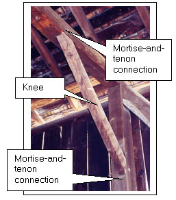
Figure 57. Traditional knee brace—Salisbury Center Bridge, Herkimer County, NY.
More recent rehabilitation projects of historic covered bridges have occasionally modified the knee braces to make them stronger and stiffer. One popular means is the use of heavier members, with extensions above the tie beams up to the rafters beyond, to form a transverse frame, as shown in figure 58. Note the longer component, projecting above the tie beam, and connected to an upper strut member, effectively making the pair of knee braces into a much stronger frame.
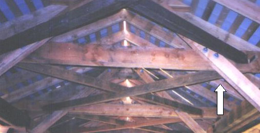
Figure 58. Alternative and stronger style of knee brace—Hamden Bridge, Delaware County, NY.
In some instances, an additional metal rod is added above the knee braces and detailed to add extra tensile capacity to the members. Figure 59 depicts such an example. Note the metal rod positioned above the timber knee brace that penetrates through the tie beam and the intersection of lattice elements. The rod adds tensile capacity to the knee brace system.
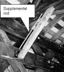
Figure 59. Another alternative knee brace—Hopkins Bridge, Enosburgh, VT.
The posts of Burr arch trusses and some other configurations are subject to substantial bending forces due to the geometrically necessary separation of the horizontal forces between diagonal and chord. Many bridges were built with check braces to help strengthen the post. Figure 60 depicts a classic installation of a check brace at a bottom chord connection to the post. In this installation, the lighter colored post has been replaced. The new check brace on the right side of the post is notched into the top of the bottom chord and resists the horizontal component of force in the diagonal notched into the left side of the post. Figure 61 depicts a check brace at a top chord, on the far side of the post backing up the horizontal force in the diagonal on the near side of the post.
Unfortunately, check braces commonly were removed during subsequent rehabilitation of bridges and not reinstalled. These elements are important and must always be reinstalled if removed. Further, in those bridges that do not have them and may not have had them initially, rather than simply strengthening the posts or replacing them with larger elements, this form of bracing element is a good retrofit option to strengthen posts that are overloaded.
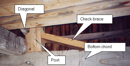
Figure 60. Check brace at bottom
chord—Brown's River Bridge, Westford ,
VT.

Figure 61. Check brace at top chord—Quinlan Bridge, Charlotte, VT.
An example of bracing common to a geographic area is a chin
brace. Many of Georgia's Town lattice trusses are fitted with a
timber brace at each inside corner that projects from the top of
the foundation, past the inside of the lower chords, to the inside
of the top chord. Its angle is steep, limiting its strength as a
bracing element and making its connections vital to its function.
Refer to figure 62 for a typical example. Due to their immediate
proximity to vehicular traffic, these elements are susceptible to
impact damage. These elements are sometimes used in lieu of knee
braces.
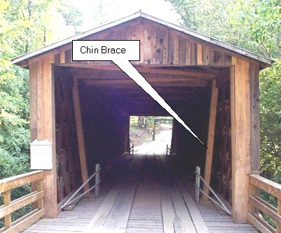
Figure 62. Chin brace—Elder's Mill Bridge, Watkinsville, GA.
Railing systems are a necessary part of modern highway design; they increase safety for the traveling public. The bridge railing system includes the railing on the bridge (bridge railing) and the railing on the approaches leading to the bridge (approach railing).
The Federal Highway Administration (FHWA) requires that crash-tested railing be used on all National Highway System (NHS) highways. For secondary roads, the State's and/or bridge owner's standards and policies should be followed. Historic covered bridges are only rarely, if ever, located on the NHS.
Virtually no historic covered bridge has ever had internal bridge railings, and most of them do not have an adequate approach railing system. Hence, the standard approach to bridge rehabilitation projects for conventional bridges, which involves installing a standard railing system, has often not been followed on covered bridge projects.
With respect to bridge railing, review of numerous recent projects prepared by various engineers at random locations across the United States demonstrates a range of treatments, from no railing at all to simple timber curbs, to a few installations using much heavier railings. The lack of standardized bridge railing for historic covered bridges has often been accepted because of the relatively low speed of the vehicles passing through the bridge and the lack of space for such a railing. An inspection of most covered bridges demonstrates that few collisions with truss members have occurred during the life of the bridge.
However, the use of a timber curb is a good addition to a bridge without any other protection, because most vehicles will not mount or cross over such a curb, and it can be bolted to the decking. The curb should be raised with timber block spacers to avoid long areas of curb directly on top of the deck, which would trap moisture and promote early deterioration of both curb and deck.
In those bridges with separate running planks along the wheel paths, the planks tend to channel the tires of a vehicle that has wandered off of them while guiding the vehicle through the bridge without danger of contact with the truss members. In these instances, the use of a raised curb is still recommended.
Figure 63 shows an example of inside curb traffic protection. While not meeting the provisions for railing protection of more modern bridges, this type of application may be prudent and practical for rehabilitation of historic covered bridges.
Figure 63. Interior curbing—West Dummerston Bridge, VT.
While some owners have adopted crash tested railing policies for building or rehabilitating other types of bridges, the use of such a railing system may typically be out of character for the rehabilitation of a historic covered bridge. Yet, the U.S. Forest Service (USFS) and FHWA have developed a number of crash-tested bridge railings for use on modern timber bridges. Some of those railings may be adaptable to covered bridges.
The accepted practice is to require more substantial railing for the approach to a covered bridge.
Many owners of covered bridges would object to the use of traditional galvanized metal railing, even for the approaches, due primarily to aesthetic dissimilarities between galvanized rails and timber bridges. In some instances, metal railing systems made of weathering steel have been used, on the basis that the aesthetically pleasing rusty patina is more compatible with the covered bridge. Some continue to use only timber railing systems.
An important aspect of railing for covered bridge projects is protecting the end of the trusses. As discussed above, it is rare when a true bridge rail is installed inside of a covered bridge; therefore, the approach rail must be terminated at the entrance to the bridge. In instances with internal curbing, the transition from approach rail to curb should be carefully aligned and detailed to adequately protect the end of the truss. Some approach geometrics will require more attention than others, depending on the specifics of the site.
An alternative approach railing system is depicted in figure 64. The tight squeeze (2.6 m (8.5 ft)) is very effective at eliminating larger vehicles and forcing slow passage.
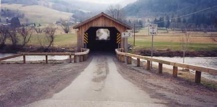
Figure 64. Squeeze timber approach railing—Hamden Bridge, Delaware County, NY.
Figure 65 shows another recent bridge rehabilitation using a standard approach guiderail with timber curbing inside.
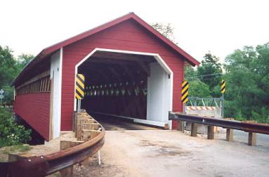
Figure 65. Approach railing and bridge curb—Paper Mill Bridge, Bennington, VT.
The transition from approach railing to bridge curbing can be highlighted with a reflector. Figure 66 presents a view of one such installation. This bridge provides for pedestrian traffic outside of the curb (but inside the bridge), and the gap between approach railing and curbing allows that passage.
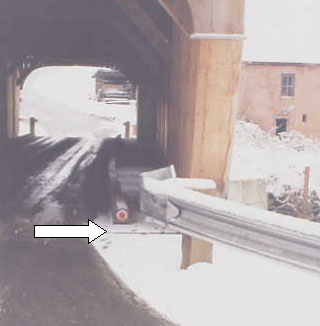
Figure 66. Transition from approach railing to inside curb—Mill Bridge, Tunbridge, VT.
Because each bridge is unique and the specific nuances of railing systems for historic covered bridges remain unclear, this manual urges careful consideration of the matter and the use of prudent engineering and construction details for work on historic covered bridges.

