U.S. Department of Transportation
Federal Highway Administration
1200 New Jersey Avenue, SE
Washington, DC 20590
202-366-4000
Federal Highway Administration Research and Technology
Coordinating, Developing, and Delivering Highway Transportation Innovations
 |
| This report is an archived publication and may contain dated technical, contact, and link information |
|
Federal Highway Administration > Publications > Research > Structures > Covered Bridge Manual |
Publication Number: FHWA-HRT-04-098 |
Previous | Table of Contents | Next
This chapter does not attempt to duplicate the basic connection information available in typical timber references. As examples, lag bolts, through-bolts, and simple bearing connections can be addressed with the NDS. Rather, this chapter presents connection issues that are unusual (and not covered in the current literature) or are of special interest to engineers working with covered bridges.
The so-called traditional timber connections used in building the historic covered bridges usually rely on traditional timber joinery-notches, wedges, bearing faces, mortises, keys, tenons, and pegs-rather than on the more common groups of steel mechanical fasteners in single or double shear, as used in more recent times. Many of these connections can be analyzed, and their capacities determined, with only some basic assumptions and allowable stresses. Allowable bearing stresses, both parallel and perpendicular to the grain, and shear and tension stresses are all that are required to assess many traditional connection capacities. Some contemporary repair methods used with historic timber bridges have relied on bolted connections. Typical wood engineering references and current timber design codes provide ample discussion of these bolted connections.
One reason that the original covered bridge builders used very few steel bolts was these bolts' relatively high cost, at the time. Many covered bridges were patented and built before heavy bolts were mass produced. In addition, heavy bolts in large patterns are not easy to install properly. Most heavy traditional timber truss members were coplanar (i.e., all sharing the same plane), further reducing the efficiency of bolts, which are best loaded in shear. Finally, heavy steel connectors condense moisture deep within even those timbers that are protected from direct weathering, fostering decay in critical zones that are hard to see without dismantling at least the joint. However, many traditional covered bridge connections did include one or two bolts. In most cases, the bolts held or clamped the timber structural components together. Although some shear or axial forces might be transferred through these clamping bolts, that capacity is rarely of any consequence when compared with the capacity of the timber joinery, and therefore usually is neglected in assessing the joint capacity.
Most timber designers do not like to discuss moment connections between two discreet heavy timbers because this load transfer is simply too hard to achieve. Therefore, coaxial tension connections (i.e., those involving members along the same axis and connected together to resist tension forces) are the most challenging joints, no matter which connection method is used.
The innate limitations imposed by traditional joinery methods are most pressing to the designers and crafters working with coaxial tension joinery. The traditional tension connections between coaxial truss components are handled with a variety of joints. These include lap joints, scarf joints, bolt-of-lightning joints, fish-plated connections, keyed joints, rod-and-tenon joints, and multiple tension chord members with staggered butt splices-reducing the impact of any single splice on the truss capacity. Some builders even used extraordinarily long members that precluded the need for tension splices. The following subsections address each type of tensile joint.
Lap joints describe a complex family of connections that extend the apparent length of the connected timbers, within the available and original cross section. The simplest lap joint overlaps halved members, with transverse (or through-plane) connectors transferring the tension force in one member to the next, through single shear forces in those connectors. Those through connectors can be steel bolts or wooden dowels. The available strength of these simple lap joints is immutably limited to less than half the gross tension capacity of the members. The net section of the lapped portion is only half of the gross. The through connectors remove further material, reducing the available tension capacity to less than half the gross (see figure 103). Transverse connectors, loaded in single shear, are not as stiff as those loaded in double shear. This means the spliced section of the tension member will not attract or resist the same tension forces that it would if it were an uninterrupted timber.
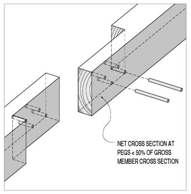
Figure 103. Simple lap joint, with through-plane connectors
A remarkable lap joint can be found in the lower chords of the Taftsville, VT, covered bridge. Those hand-hewn 350- by 450-mm (14- by 18-inch) members overlap for a full 7.3 m (24 ft). The tension forces are transferred between those two members and across the lap length through shear keys and bolts.
In other lap joints, connectors are lying in the shear plane; in these joints, wooden keys or dowels are the most common in-plane connector form (see figure 104). Again, the net cross section is further reduced from the half that is the lapped timber. The dowels and most shear keys are oriented with their grain lying in the same shear plane, but perpendicular to the longitudinal axes of the spliced members. This grain orientation is a compromise made for the convenience of the builders in the face of available wood component sizes. The dowels or keys are oriented so they are being crushed in side grain, as opposed to end grain, bearing. This is a weaker loading direction, by a factor of about double. Furthermore, the dowels or keys are being sheared in a way that results in their fibers or cells being rolled by one another instead of along each other. This rolling shear stress capacity is about half of that found in along-the-grain shear stress. Figure 105 shows side grain bearing and rolling shear stresses.
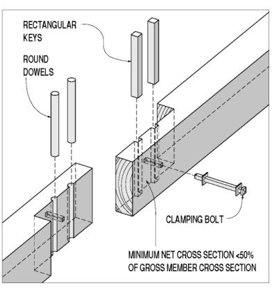
Figure 104. Simple lap joint, with in-plane connectors.
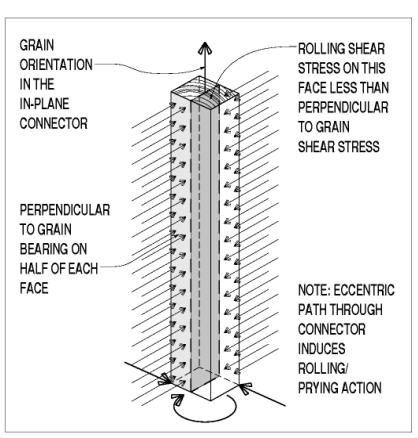
Figure 105. Grain orientation of rectangular in-plane connector.
Some lap joints avoid using either through-plane or in-plane connectors by removing enough of both members to leave room for a direct end grain bearing surface between them. The allowable end grain bearing stress is higher than the side grain bearing on the dowels or keys. Because of the deeper notching involved, the theoretical capacity is still less than 50 percent of the gross, but the simpler and stiffer end grain bearing offers significant upgrades in overall performance. The craftsmanship required to generate uniform and even bearing surfaces can be daunting, however, when compared with the skill involved in installing through-plane connectors. Some builders overcome this fitting challenge by putting tapered shear keys (or wedges) at this bearing seat. While achieving uniform bearing more reliably, this advancement also introduces side grain bearing faces, with their reduced capacity and stiffness. There still is a shear stress consideration in these bearing lap splices-the shear capacity of the section between the bearing face and the end of the spliced member. This shearing along the key line is actually the most common failure mode for these splice joints. Figure 106 shows an example of a lap joint with bypassing leaves and end grain bearing surfaces, also with tapered wedge.
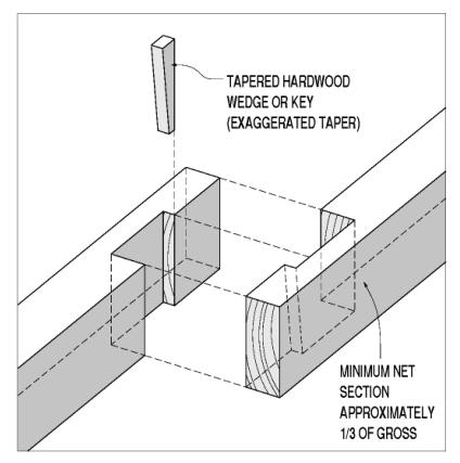
Figure 106. Lap joint with bypassing leaves and end grain bearing surfaces.
One relatively simple but effective way to increase the available tension capacity in a lap joint is to taper the breadth of the halves as the load is transferred from member to member. If the members taper from two-thirds of their gross section at the beginning of the splice to one-third at the end of the splice, the through connectors might weaken the splice to only one-half of each member's gross tensile capacity. Again, both through-plane and in-plane shear connectors can be used to transfer the axial tension from one member to the other. Figure 107 shows a lap joint with tapered halves and connectors.
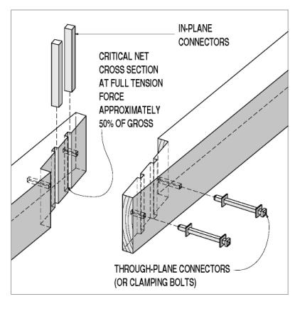
Figure 107. Lap joint with tapered halves and connectors.
Within the family of tension lap splices, perhaps the highest form in efficiency, required craftsmanship, and artistry is the bolt-of-lightning splice (see figure 108). This joint is a tapered, end grain bearing splice with multiple bearing faces. The bearing faces are not cushioned with side grain bearing wedges or keys, and each of the mating faces must be scribe-cut to fit. Furthermore, if only one of the faces is overcut, one of the members would have to be replaced.
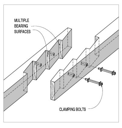
Figure 108. Bolt-of-lightning joint.
All lap splices, from simplest to most complex, share an innate design consideration-eccentricity. The eccentricity comes from two sources. The very halving of the members deflects the load path from the gross section centroid through the net section centroid within the lapped zone. The in-plane connectors also will induce prying forces in response to the eccentric load flow paths through them. The connector eccentricities require clamping through-bolts to hold the lapped members together. The overall eccentricity also induces secondary moments about an axis in the lap plane, which can cause splitting, usually right at the necked transition from full to lapped member (see figure 109).
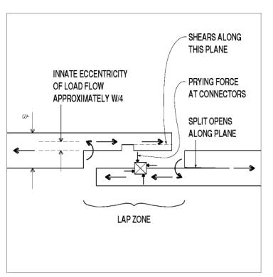
Figure 109. Eccentricity in member layout and prying at connectors.
Some builders tried to counter this splitting tendency with more through bolts or lags. Some of these clamping bolts were not threaded, because steel hardware was so costly, and the machinery needed to roll or cut threads was not commonly available. Instead, builders would use an eye-and-wedge connector, which was built at the local blacksmith shop (see figure 110).
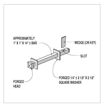
Figure 110. Eye-and-wedge clamping bolt, hand-forged.
One apparently simple but rare modification to the lap joint is the doubled lap, or slot and tenon joint. This connection represents an improvement in two ways over the entire family of simple lap joints. The through-plane connectors are loaded in double shear, with more than twice the capacity (generally) and increased stiffness over the single-shear use of the same connector. The innate eccentricity is also removed with this symmetric layout. Although through bolts still would be a wise addition, the clamping of the double leaved half resists the prying action generated at the connectors. If the leaves were also tapered, the theoretical capacity of this splice layout could approach 50 percent of the gross capacity, with greatly reduced eccentricity-induced influences (see figure 111).
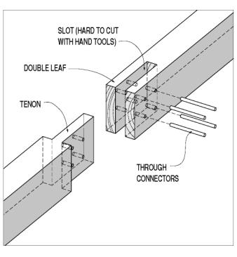
Figure 111. A double-leaf lap joint, with through connectors.
For various reasons, including fabrication and timber checking, timber joiners rarely used this double-leaf layout, but they gained many of the advantages of its straightforward load flow and doubly sheared connectors through various renditions of the fish-plated tension splice (commonly termed splice plates in metal truss bridges). In a fish-plated connection, the tension forces are not transferred directly between the two spliced members, but rather from one to the other through intervening members that are outside the butted gross cross sections of the spliced members. The simplest fish plates are two steel plates, through-bolted to the two members (see figure 112). This is a common repair method, but it is rarely used in original construction. This connection shares the fabrication and long-term maintenance problems described in the introduction to this section.
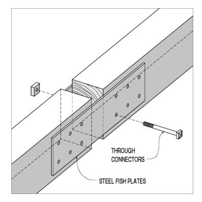
Figure 112. Butt joint with steel fish plates.
Original builders often used wooden fish plates that were clamped to either side of the tension chords and relied on end grain bearing faces to transfer the tension forces (see figure 113). The bearing faces could be fit and cushioned with side grain bearing keys and wedges. The shear lugs could also be tapered to generate full bearing faces with fewer and smoother reductions in the net section. In addition, the fish plates could have multiple bearing faces, resulting in a fish-plated bolt-of-lightning joint. These joints had one big advantage over executing the same joint in two lapped members: If one bearing face was overcut, only the fish plate had to be replaced to achieve uniform bearing faces, equally sharing the transferred tension forces. The theoretical tension capacity of these fish-plated connections can still barely exceed 50 percent of the gross capacity in the spliced members, depending on the relative allowable stresses in tension and end grain bearing.
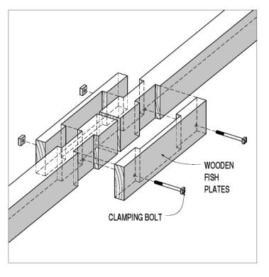
Figure 113. Butt joint with fish plates-wooden plates.
The bars-and-rods splice is a marriage between timber joiners and the blacksmithing crafts (see figure 114). A through mortise is cut (usually vertically through the member depth) a certain distance from the simple timber butt cut. A cast iron bar passes through this mortise and has holes at both top and bottom, beyond the timber cross section. Wrought iron or steel rods with threaded ends pass between the two iron bars and carry the tension force. Failure modes for this type of connection include bending in the bar, crushing in the wood bearing face, shear in the wood end grain, and fracturing or stripping threads in the rods.
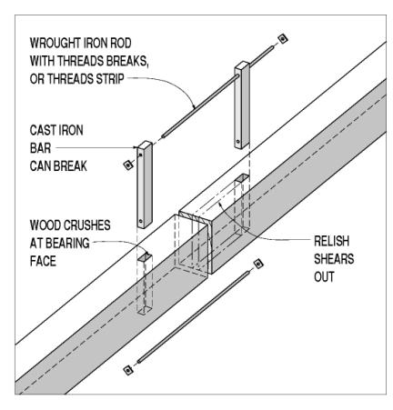
Figure 114. Butt joint with bars and rods splice.
Of course, no mechanical connection method can approach the capacity and stiffness generated in the straight wood fiber found in a tree. The best tension chord for a timber truss is a full-length single piece. Some very short bridges took advantage of this. For the longer spans that a heavy timber truss can handle, however, builders rarely had access to full-length tension chords. Some of the World War II-era bridges built on Oregon State highways have 30.5 m (100-ft) chord members. A few recent rebuilds of existing bridges have used full-length, glue-laminated timbers. Those projects have further illustrated the difficulties in handling these long and fragile members, even with modern roads, trucks, and lifting equipment. Even in cases where a tall enough tree might be available, the logistics of transporting a timber cut from its log to a convenient bridge site can be daunting enough to require builders to use various splicing technologies instead.
Compression connections between coaxial members are often variations on the simple half lap, or lapped splice joint (see figure 115). Theoretically, one might assess the compression load bearing capacity of this joint as being close to that of a continuous timber. The two factors working against this are uniform bearing on and between the two separate bearing faces, and the allowable end grain bearing stress.
Achieving uniform bearing across each face, and even bearing between the two sets of bearing faces, is a true test of the timber joiners' abilities.
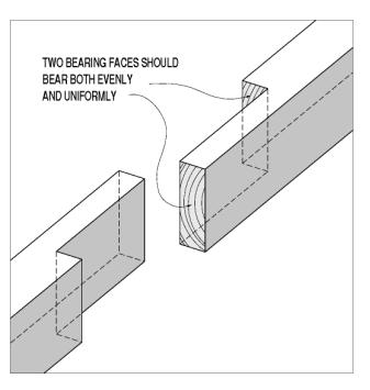
Figure 115. Simple lap joint for compression members.
One trick that the original fabricators had the luxury of using was kerfing to the line. This technique, described in Milton Graton's book, involves fitting the splices in a long compression chord before cutting the intervening joinery to the other truss members.[16] The two halves of the lap joint were cut to reasonably close tolerances and the two timbers mated and pressed toward each other as tightly as they will fit. The two timbers are clamped in that position, and a saw is run between them at both sets of bearing faces. This creates a pair of similarly sized and parallel-faced gaps at the bearing faces. When the timbers are unclamped and pressed together again, they should now bear uniformly and evenly. If they do not, the joiner repeats the process until the four faces bear well, uniformly, and evenly.
The NDS values for allowable end grain bearing have been reset to a maximum that is the same as simple compression along the wood grain. The NDS does permit an increase to this value, with the addition of some steel bearing plates. This reduction in allowable stress is reasonable, and reflects the reality that the wood fibers are interrupted along an entire cross section, making them free to crush into each other and not transfer the compression forces as directly and smoothly as do the naturally overlapping cells and fibers.
Generally, tension connections are detailed more easily between members that are perpendicular with (or parallel to) each other, rather than at an acute or oblique angle. Most timber trusses, therefore, are designed with compression diagonals and tension verticals. Furthermore, the diagonals generally frame into the verticals, rather than directly to the chords. This eccentricity can tend to shear the verticals, but offers tremendous simplifications and stronger connections. The result is that this subsection primarily describes only the heel, or end, connections found in queenpost and kingpost trusses, yet is applicable to other more generic locations, as the title indicates. These connections are, simply, examples of the most heavily loaded version of the classic truss connection: the last diagonal before the support reaction. Another categorization would be connections in which compression force is transferred between two timbers that are in-plane, but at an angle with each other-not coaxial, in other words. Given the large component that timber truss dead loading constitutes, the end diagonals are usually the most heavily loaded compression members in the truss. The structural issue is determining how to keep that last diagonal from sliding off the end of the bottom chord. The classic connection at the heel joint in queenpost trusses has long been a notch in the top face of the bottom chord(s), cut at an appropriate angle for equal bearing stresses in both members, and secured with a centered clamping connector (see figure 116). The allowable bearing stress in wood varies from maximum (when parallel to the grain) to minimum (when bearing on side grain). Between those two limits, the transition is not linear, but is modeled with Hankinson's formula (a commonly known formula used to calculate loads at an angle to grain.) The optimal angle for the bearing faces occurs when the angle between the grain and the bearing faces is equal in both members of the connection. The bottom chord is the more critically notched and loaded member of the two involved in this joint.
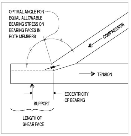
Figure 116. Simple bearing joint at angled notch.
The stresses that need to be considered at the bottom chord notches include:
This last consideration is a prime reason that original builders used bedding timbers to cushion the point reaction at the supports, while providing some distance along the bottom chord for resisting heavy bending and shear stresses induced by the joinery design. Another way to view this connection is to recognize that the support reactions are the largest point forces applied to the trusses. The high forces transmitted among the members in this area mean that these connections will be the most difficult to design, no matter what truss format is used. The pegs in Town lattice trusses, for instance, are much more heavily loaded in shear near the supports than anywhere else in the truss.
Connections between truss verticals and their horizontal chords will be, by definition, joints where the members are perpendicular to each other. Generally, the primary force resisted is the tendency for the lower chord to be pulled off the bottoms of the verticals, and the shearing force is transmitted from the diagonals to the chords, through the verticals. A common feature found in connections between vertical elements to both upper and lower chords is the bearing face table, usually in both members. These bearing faces often are seen only in both members in the bottom chords of non-Town trusses. The single top chord in most timber trusses is suited only to provide bearing faces in the vertical plane-along the mortise-and-tenon ends and, possibly, the bearing at the table or housing in underside of top chord timber. These interlocking dadoes lock the joint together against both vertical and horizontal relative movements. The forces are transferred between the connected members through bearing between end grain and side grain faces (see figure 117).
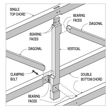
Figure 117. Top and bottom chord connections to vertical.
In addition to the often large, in-plane longitudinal truss shear forces that must be transferred at this joint, the connection between bottom chords and verticals often transfers vertical loads from the transverse floor beams that bear on the bottom chord into the truss verticals. These live and dead gravity loads can be substantial and must be transferred into the truss verticals to prevent inducing undue secondary bending stresses in the truss bottom chords. The original builders prevented the bottom chord from sliding down the vertical by making clever double use of the multiple bottom chords, through double tables that bear on the blocks remaining on the exposed bottoms of the verticals. For this bottommost truss element to have adequate shear capacity against these vertical reactions, they must have sufficient length in the tail hanging below the truss. The exposed lower tails in these truss verticals often hang at least 250 mm (10 inches) below the bottom surface of the bottom chord. This critical but exposed component can be subject to the most intense damage by floating debris during high water flows.
The heavy timber truss verticals often were crafted with corbels where the verticals receive the largely compressive diagonals at simple bearing face connections. This means that the total width of the vertical, at its ends, is several inches wider than its net width along the central portion between the notched corbels. In other words, the net section is reduced between the bearing faces at the tops and bottoms of these tensile members. The vertical component of the compression force in the diagonal is resisted by shear parallel to grain along the length of the corbel beyond the bearing face. It is common that some of the more heavily loaded (nearer the span ends) vertical corbels have failed in shear along this section-a condition that can be very serious and should be addressed immediately, as depicted in figure 118.
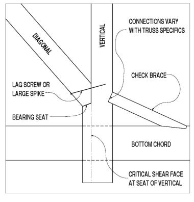
Figure 118. Truss vertical at bearing seat with critical shear face.
Unfortunately, it is not easy to repair a vertical with corbel shear failure. Some have attempted to repair the failed shear plane with epoxy adhesives. Others have installed bolts in single shear through this face, but this will rarely provide sufficient capacity to restore the connection to a safe condition. Still others have sistered another diagonal within the original one, bearing on a newly cut bearing face in the vertical member. This induces even more eccentricity in the connection force layout, with increased bending in the vertical member. Figure 119 depicts a sistered diagonal.
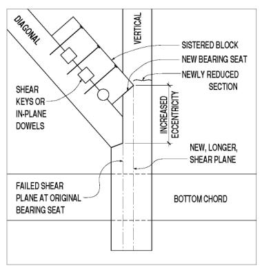
Figure 119. A sistered diagonal.
The most practical solution is often total component replacement, a solution that usually requires false work supporting the structure while the truss is partially disassembled in the vicinity of the vertical needing replacement.
Similar to the stresses induced in the queenpost bottom chords at the supports, the verticals in these paneled timber trusses need to be investigated for some secondary stresses. The innate eccentricity at these joints greatly simplifies their crafting and bearing surfaces, and reduces the shear that the vertical to chord connection must resist, but these gains are made at some cost. The horizontal component of the diagonal compression force induces bending and shear stresses at the reduced net section in the vertical. Furthermore, the combined tensile stresses should be checked for net section at the notch, because the secondary bending stresses caused by eccentric load paths can be even more damaging. Not only are these stress combinations complex, but the designer must confront some fairly complex and cloudy load flow and transfer geometry, when considering how the vertical is restrained by the chord member just beyond this connection to the diagonal. Some original timber truss builders and many subsequent builders addressed this connection eccentricity by introducing check braces on the face of the vertical opposite the diagonal. These braces, typically at flat angles, can carry the horizontal component of the diagonal's compression very efficiently through the vertical, into the check brace, and then into the chord member. See figure 118 for an illustration of these fairly common reinforcing braces.
Supporting and partially disassembling heavy trusses in situ can be difficult and expensive, so many rehabilitation efforts avoid this process. Partially replacing the failed bottoms or tops in the verticals has been common in a variety of truss types. Because the verticals are usually resisting substantial forces, even if simply generated through dead loads, splicing the partial replacement is an operation demanding careful design, detailing, and execution. Repair connection methods include using timber shear keys, or pegs drilled in the lapped planes, in combination with bolts to hold the components together. These clamping bolts must be designed to resist the prying action caused by the eccentric load path through the single shear passing through the mechanical connectors within the shear plane. The size of the prying force is a function of the number and loading within the connectors, as well as the length-to-thickness ratio of these shear keys or dowels.
The common problems with corbel shear in the ends of truss verticals led to using wooden pegs to reinforce the critical shear plane. Figure 120 shows an installation that increased the vertical capacity of the joint by about 15 percent. Unfortunately, wooden pegs are not common enough to have standard allowable stresses. Furthermore, the wooden dowels, loaded in single shear, seem likely to be significantly less stiff than the original shear plane. This means that the shear plane area is reduced by the cross-sectional area of the peg holes drilled through it. However, the pegs might not be considered to be bearing much load until after the shear plane has failed and displaced. This load sharing between disparate but parallel interconnection methods, based on their relative stiffnesses at various load levels, is a common problem for designers who conscientiously combine connection methods within a single joint. The most reasonable, but conservative, approach would be to design the added shear connectors to carry the entire design load, without relying on the stiffer, but more brittle, along grain shear capacity in the corbel block shear face.
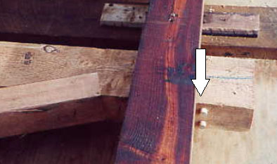
Figure 120. Example of pegs added to increase the shear capacity.
Timber counter members are found in only a few truss types, including Long trusses and Howe trusses. Figure 121 shows a Long truss with counter timbers. The dual diagonals are the main compression diagonals; the single diagonal elements are the counters. Unlike the steel rod counters used in classic through truss bridges, timber counters are expected only to act as compression members, and the simple butt-fit bearing face joinery can transfer only compression forces. The stress reversing effects of moving live loads can loosen these timbers, as they inevitably fail to carry induced tension forces. Timber counters are often toe-nailed in place, with relatively light steel fasteners, to keep them from falling out with heavy moving live loads.
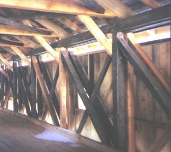
Figure 121. Long truss with counter timbers.
When timber counters were used, initial installation usually involved matching bearing wedges-often at the bottom end of the counter member-which could be driven (and adjusted, even much later) to produce a desired tightness, or precompression, in the counter member. Unlike metal counters that can be adjusted to a desired force level by measuring with strain gauges while tightening an adjustment linkage, timber counters are usually installed or retightened solely by judgment and experience. A popular and simple approach involves intentionally shaking the counter timber. If it feels loose, then the wedges are driven against each other, causing more resistance when shaking the element. This is not a high-tech method, but it is practical and sufficiently effective for most covered bridges with counter members.
Apparently, the matching wedges at the counter ends were rarely secured with nails or screws when they were originally installed. Current rehabilitation projects often involve adding these fasteners to prevent the wedges from working loose under the load reversals induced by traffic live loads. Screws offer the advantage of being easily removed when additional adjustment is subsequently required or desired.
The Howe truss was the first patented truss type to use metal in primary truss components in concert with the majority of members still made from timber. The vertical tension elements were made with wrought iron rods with threaded ends that allowed the builders and owners to tighten the truss panels against the wooden compression diagonals and counter members. This adjustable feature accommodated more variation in assembling prefabricated elements, simplifying and speeding bridge fabrication and construction. The connection blocks used on the first Howe trusses were hardwood. Later versions of the Howe truss took advantage of mass-produced cast iron shoes.
The Howe truss was quickly adopted for use on the developing railroad network in the 19th century because it could easily and quickly be built of components that were mass-produced offsite and erected onsite with the easily adjusted vertical rods to tighten the trusses. Because the railroads were large and wide-ranging, the Howe truss bridge details were often standardized. Examples of high-quality technical drawings of those standardized details are more readily available than any other early heavy timber truss.[15]
The Long truss is notable because it relies on bearing wedges between the truss verticals and the chords. These wedges are not particularly consistent and may or may not be present in the top chord connection. The top chord wedging apparently depended solely on the preference of the original builders. Many covered bridge scholars have proposed that these wedges were originally intended to allow the builder to adjust the overall truss geometry (and thereby, internal forces) in an early example of structural pretensioning. However, recent work on a covered bridge in Hamden, NY, demonstrated that these wedges may be far more important in distributing large, cross grain bearing stresses from the verticals into the chords. More discussion of this topic is available in an article about repairing this particular bridge, contained in appendix B.
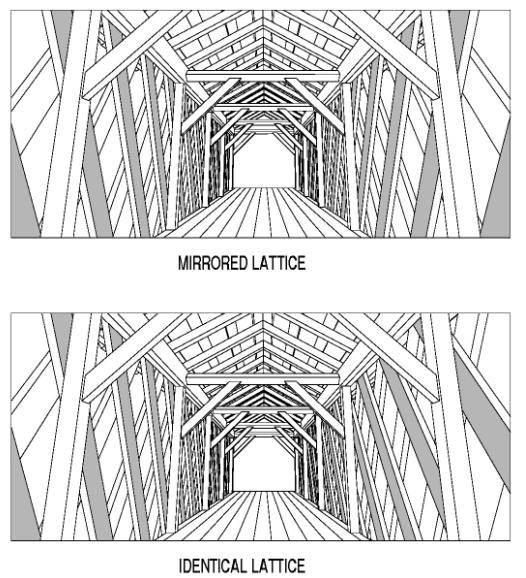
Figure 122. Town lattice trusses with identical versus mirrored web members.
A few of the larger and longer Town lattice trusses were built with only a single chord element on each side of the lattice web or core. These large, sawn members had to be spliced together, using one of the many forms of tensile and compressive element splices discussed earlier. One of the more notable examples of this type of truss variety is the Windsor-Cornish Bridge over the Connecticut River between Windsor, VT, and Cornish, NH, rebuilt in the early 1990s to support two lanes of truck loading.
In general, the Town lattice trusses originally were connected only with wooden pegs (termed trunnels, derived from the term treenails) at each of the intersections between elements. The pegs are in groups of as many as four in the chord to lattice connections, and one, two, or even three pegs at the simpler interlattice connections. The interlattice pegs are loaded in simple single shear, but with some complexity added by the entirely possible moment constraints about a horizontal axis through the peg group centroid. The peg patterns at the chord-lattice intersections perhaps experience simpler forces, but they are complicated by passing through as many as six separate members, with five distinct shear planes. These are not doubly sheared pegs, but ones in multiple single shear conditions, with the shearing force pointing in different directions at each shear plane-a very complex loading state on any single peg. Rehabilitation projects in the latter part of the 20th century occasionally used large steel bolts to replace the original wooden pegs. This practice is not necessary and sometimes even harmful to the bridge, because it dramatically alters the original relationship of wood against wood bearing.
The traditional Town plank lattice construction used planks for the chords that were not particularly different from those used in the web members. Indeed, this multiple potential use was a prime feature of the Town lattice truss. It allowed for simpler lumber orders, while still permitting the builder to sort for the higher-quality timbers for use in the more stressed zones. This meant, however, that individual pieces of the chords generally were not very long. In keeping with the prevalent simple connection details in this truss type, no splicing was made between individual, coaxial, tension chord elements, at least not in the traditional sense of the word "splice." Instead, one of the chord pairs on either side of the lattice was simply terminated. These simple chord butt joints were usually staggered carefully and evenly along the bridge span. In simplified concept, the adjoining chord element at each of these butt joints must be picking up the extra load that had been shared with its twin. Clearly, if the twin elements terminate too close to each other, the load shifting between the two halves of the paired chord will not be effective.
As relatively simple as they all may seem, each Town lattice truss is unique in at least some ways. The truss's behavior strongly depends on the length of the individual chord elements; the size, angle, and spacing of the lattice members; and the number and diameter of pegs used at the connections. The surviving original Town lattice trusses were typically built with individual chord elements that were at least 9 m (30 ft) long. The load sharing and transfer required between the paired chord components is critical and benefits from longer chord elements; those built with shorter chord elements would not have lasted as long as those built with longer elements. The longer chord elements reduce the overall number of the weakened splice cross sections while allowing more mechanical interconnections between adjacent chord terminations. The longer elements also permitted more advantageous positioning for the staggered terminations among the four chord lines, to minimize the number of butt joints in any one cross section of the full chord.
Refined computer model analysis and strain gauge field measurements have demonstrated that some portion of the axial forces in an interrupted chord is transferred through the trunnel connections to lattice members to the pair of chords on the opposite side of the lattice truss. Further generalization about the load sharing among various chord elements in Town lattice trusses is difficult, because it depends on the length of individual chord elements, their joint locations, and the strength and stiffness of the trunnel connectors. More discussion of this work is available in the article, "Those Intriguing Town Lattice Timber Trusses," presented in appendix A.
Another structural aspect related to the lower (or tension) chord ends is the gap size between the two chord elements at their terminations. Given the dominance of the truss's uniform dead load, the chord forces are larger toward the middle of any truss span. The upper chords are in compression and tend to close any gaps between the ends of members. The lower chords are in tension, which tends to widen any gap. The gaps at the terminations in both upper and lower chords nearer to the abutments, with their reduced axial forces, indicate the tolerances met by the original fabricators (or subsequent repairers). The authors have inspected many of the authentic covered bridges in the United States and have found that the original joint fabrication tolerances were quite good, to 3 mm (0.125 inches). A small gap at a tension chord termination indicates that the truss is operating within stress levels; this further implies a reasonable safety factor. Some bridges exhibit distinct gaps (larger than 25 mm (1 inch)) between the tension chord ends. Gaps this large can only occur when the wood surrounding the nearby trunnels crushes and/or the trunnels themselves crush or bend. While a 25-mm (1-inch) (or more) gap between the ends of tension chord elements raises reasonable concern for structural inspections (see figure 123), smaller gaps (6 mm (0.25 inches) or less) are not generally cause for alarm.
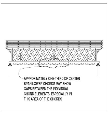
Figure 123. Town lattice truss connections need to be inspected carefully.
The connections between the chord and lattice elements must rely solely on the shear capacity of the trunnel patterns to transfer the forces from one element type to the other. Because the lattice members end just past their connection to the chords, all the forces (axial and shear) remaining within the lattice members must be transferred to the chords at that connection. Similarly, the horizontal force components in the chords on one side of the lattice elements must be transferred via the trunnels at those lattice/chord connections adjacent to chord element terminations.
The finite element computer modeling cited above consistently and clearly indicated that the most heavily loaded trunnel connections in any lattice truss span are those directly above the supports and closest to the front edge of the abutment. The total shear forces in these trunnels can be many times higher than those found in any other trunnel location within the truss. This uneven trunnel loading has led some Town lattice truss designers, analysts, and builders to advocate using more trunnel connectors at the span ends, and fewer in the center portion of the truss span. One might use four trunnel connections in the end quarters of the span and three trunnel connections in the center half of the span, for example. Some trusses even varied the lattice member spacing and breadth along the span length, further reflecting the varying shear forces along a span.
Another structural issue involved with the connections between lattice and chord members is transferring the transverse floor beam end support reactions, via bending and shear in the inner bottom chords, into the truss as a whole. Floor beams that extend through the lattice elements and are fitted to bear on all four lower chord elements can transfer their support reactions to the trunnels more uniformly. In many bridges, however, the floor beams bear only on the innermost bottom chord pairs, thereby adding substantial shear and bending forces to those trunnels that connect that inside pair of chords to the truss as a whole.
All these force transfers mean that the stresses in the trunnels are a very complex composite of shear and bending. This situation is induced by longitudinal and vertical distribution of forces among and between the many elements in a truss chord to lattice intersection.
The refined computer modeling cited above has not indicated that high shear forces are being transferred by trunnel patterns within any lattice to lattice connections. In practice, most of these interlattice connections have been made with a pair of trunnels, although some are made with only single trunnels, while others are made with three peg patterns.
As described in the introduction to this subsection, traditional Town lattice trusses were assembled and connected with wooden pegs that were usually 37 to 50 mm (1.5 to 2 inches) in diameter. Minimal technical information about how these wooden dowel connectors behave pegs has been published in North America. Robert Fletcher and Jonathan Parker Snow published valuable information about timber-covered bridges in the late 1800s, based on Snow's extensive experiences on railroad bridges in New England. Their work includes some information on wooden pegs.[17]
Milton Graton, the renowned (and nearly only) authentic covered bridge builder in North America from the 1960s through the 1980s, published a book describing his life's work.[16] That book cited the results of a few trunnel tests, and they were very specifically patterned on the connections he used to build lattice truss bridges. Those tests also apparently only determined failure loads, not connection stiffnesses. Robert L. Brungraber's unpublished, but available, Ph.D. dissertation also included some peg testing results, both strength and stiffnesses, in axial tension and compression, double shear, and bending loads.[18]
William Bulleit, Ph.D., and Richard Schmidt, Ph.D., PE, have extensively tested pegs. Their research has been meant to determine those behaviors that will allow wooden pegs to be analyzed with the current NDS model for dowel connectors.[19]
This model was, in turn, based in the Lateral Yield Theory methodology, which was first used in Europe in the 1970s. Section 11.7.1 of the 2001 NDS mentions how to address dowel connections with alternate materials or methods-opening the door to using wooden peg parameters to calculate shear capacities with code-approved methods.[3]
As of this writing, however, there are no nationally recognized allowable design forces for these wooden dowel connectors. Pilot testing work, done in the mid-1990s, in combination with related finite element modeling, established that a reasonable single-shear allowable force for a 44-mm- (1.75-inch) diameter oak trunnel in a chord/lattice connection of 75-mm- (3-inch) thick pine is 6.7 kilonewtons (kN) (1,500 pounds) per shear plane. More testing follow up would be helpful.
Most of the Town lattice trusses in authentic covered bridges have been rebuilt over the years. That work, at times, has been characterized by extraordinary care and was committed solely to replacing failed or deteriorated elements in kind. Some repair efforts involved substituting large diameter metal bolts for the original and traditional wooden pegs. The wooden peg connection functions through bearing between wood and wood, with effects on both the peg and the surrounding material. The steel bolt in wood connection, with the much stiffer steel, often displays increased deformation in the surrounding wood material, with higher stresses in the wood at its edge, and relatively little bending of the steel (for the large diameter bolts used in this situation.) Some researchers believe that substituting steel bolts where there had been wooden pegs may actually weaken a connection, due to the higher edge stresses. The lack of any accepted standards for this connection type allows personal and professional judgment to influence preferred practice. The authors of this manual have not yet observed an instance where substituting bolts for wooden trunnels was either an obvious advantage or even necessary.
Diameter tolerance and the likelihood of uniform load sharing are two reasons to connect heavy timbers with larger diameter wooden pegs rather than steel bolts. The NDS specifies that steel bolts be installed in holes drilled up to 3 mm (0.125 inch) oversized, recognizing that wood may shrink as it dries, while steel will expand and contract with temperature shifts. Large diameter steel bolts are stiff, as compared with the connected timbers, so load sharing between patterns of bolts can be particularly uneven. One bolt, in a large group of similar bolts but installed in slightly misaligned holes, can be easily loaded with far more (or less) than a simple averaged share of the load. This uneven load sharing among large groups of heavy bolts has led to progressive collapse in large timber structures-particularly when the bolts were used in tension chord splices in timber trusses. Large wooden pegs, on the other hand, can be driven into tighter holes, even to the point of a mild interference fit. This means that all the pegs in a large pattern should bear more evenly. The reduced bending stiffness of the wooden dowels also helps the patterns of pegs distribute the loads more uniformly. Finally, wooden dowels do not condense moisture any more than the surrounding timber, reducing the risk of decay within the holes.
Although not exactly considered a connection between two distinct truss elements, sistered lattice (or angled, web member) elements (newer supplemental elements slid into place along a deteriorated/damaged existing lattice element) fit into this discussion of Town lattice truss connections. Installing a new element adjacent to a damaged lattice member requires that the new one be connected in a way that effectively participates in the load sharing within the truss components. The original lattice elements were connected into the truss by trunnels at their intersection with the chords and with the intersecting lattice members in the other lattice layer. Those original trunnels helped transfer vertical and horizontal shear forces between adjacent lattice layers in the truss. Because the sister lattice elements are inserted along the original lattice member, their connections do not allow the mutual interconnection across all six planes of truss elements at the chord-lattice joints. The added trunnels at those intersections can only connect the four chords and the new single lattice and, therefore, do not provide an entirely similar connection to the other lattice layer, as found in the original construction. While these additional sister lattice elements have been used for many years, connecting them into the existing truss timbers is done more by judgment and less with benefit of any analytical investigations. See figure 124 for an example connection of a sistered lattice web at a chord.
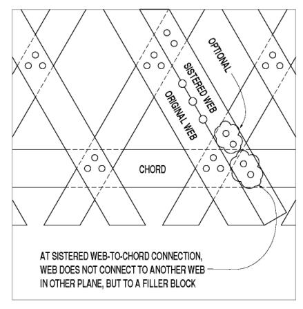
Figure 124. Sistered lattice web at chord connection.
One major and distinctive feature of the Town lattice trusses was that they could be "built by the mile," meaning that the truss members could be extended and repeated for as long a bridge as the builders desired. This extruded nature also means that there is no single, obvious way to terminate a Town lattice truss. Furthermore, the builders' choice for detailing the ends is rarely visible, unless the bridge is being repaired and the siding is removed. The truss ends need some type of auxiliary stiffening to help resist lateral buckling in the trusses and provide more support for the end portal bracing. Builders and rebuilders have used many methods to provide this end treatment.
The most common geometric treatment at the truss ends was to cut them vertically (at right angles to the chords, for those bridges on a longitudinal grade). This vertical end post often is made from the same plank members as were the chord and lattice members, and is cut to fill in the vertical gap between the chord ends at the truss termination. Many of these posts were made by extending all chord members to the truss end and filling the vertical openings with extra timbers around the lattice elements. The strongest way to form these end posts, however, is to alternate the continuities of the post elements and the chord elements to knit the two groups of elements together, as shown in figure 125.
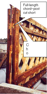
In some instances, the end posts were made from solid sawn timbers rather than planks. The chord members were connected to the posts, but the lattice members were cut short and not connected to the post timbers, as shown in figure 126.
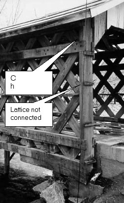
Figure 126. A solid-sawn end post-Fuller Bridge, Montgomery, VT.
Many Town lattice trusses are finished with an inclined, overhanging end that follows the line of the lattice (see figure 127).
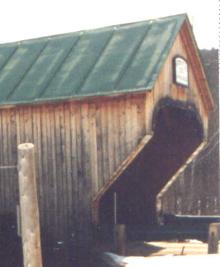
Figure 127. An inclined end treatment-Bartonsville Bridge, Rockingham, VT.
In these inclined end bridges, the trusses require end posts that are located back along the truss, where the trusses are still full-depth, and usually over the end support bearing points (see figure 128).
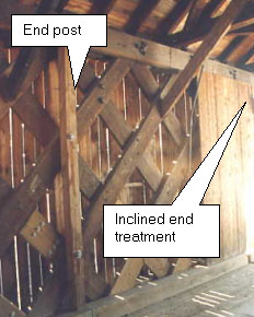
Figure 128. The corresponding interior end post-Bartonsville Bridge, Rockingham, VT.
In more rare instances, the posts are located at intermediate locations and were probably not included in the original construction. Figure 129 illustrates one example of this member layout.
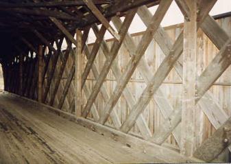
Figure 129. Intermediate posts-Worrall's Bridge, Rockingham, VT.
For the end posts depicted in the "Vertical Ends" section above, historic preservation principles usually indicate the need to repair or replace a solid-sawn end post, when it exists, to retain the practice of original construction. If the end post is built from smaller plank components, and if the repair process allows it (which depends on which chord elements are being replaced), the combination post-with alternating chord and post elements being continuous-produces a much stronger composite element. This shuffled method is preferred to end posts with all the chord members extended to the bridge end and the posts filled in from a collection of smaller components.
With the other post arrangements-either those near the ends of a truss with an inclined end treatment or those with intermediate posts (discussed in the "Inclined Lattice Truss Ends" and "Intermediate Lattice Truss Posts" sections, above)-the post components are interrupted by the chord members that must be continuous at that connection. The post components typically are solid sawn, with a thickness that equals a chord member pair. They are cut to fit tight at both top and bottom, wedged in each space between the chord members.
The intermediate posts located away from the ends of the spans may not offer much benefit to the truss load-carrying capacity, but they can offer extra lateral stiffness and strength to the bridge through the much stronger connection orientation for the knee brace connections. These intermediate posts may have been added during a partial rehabilitation of the trusses, in an attempt to avoid a more substantial lateral strengthening project.
The tails of the lattice members extend below the bottom of the bottom chord members to provide an adequate end distance beyond the trunnels at that critical connection. If these tails were eliminated in the lattice members that are in tension, the connections would tend to fail through the lack of sufficient shear strength in the relish (shear plane) from the trunnel to the end of the lattice member. However, at the bearing areas, these tails are in the way below the bottom chord.
There are two ways to deal with this issue. The most common method is to cut the tails flush with the bottom of the bottom chord in that area. Because the largest lattice member forces at this area are in compression, the lack of an adequate tail does not weaken the truss in any significant way. After the tails are removed, bearing blocks can be installed beneath the chord members. Bearing blocks should be placed directly beneath the lattice intersections above the bearing area. At least two lattice-chord intersections should be supported in this way. The bearing blocks are full width, supporting all six planes of truss components. See figure 130 for an example.
The other way to deal with the lattice tails at supports is to keep them at full length over the bearing area. This could be accomplished in two ways. One method is to use a set of blocks under the outer chord pair and another set of blocks beneath the inner chord pair. It is difficult to shim the chords and blocks equally, so one side tends to bear more heavily than the other side. This introduces an eccentric load into the chord that causes torsion in the chord and uneven shearing in the trunnels. Rebuilders should avoid this detail, if possible, and shim carefully if they must use this split-bearing method.
A second way to detail split-bearing supports is to use a large solid-sawn timber with a groove cut into the top surface. This groove should be sufficiently wide and deep to allow the tails to protrude into the groove without bearing on their bottoms, while the chords bear on the outside of the timber. This detail is extremely rare and is not recommended, because the groove is a natural moisture and debris trap and will lead to early deterioration in the bearing timber.
Theodore Burr is credited as the first to superimpose an end-bearing, two-pinned timber arch with a traditional multiple kingpost truss. Since his first patented layout, many covered bridges have seen various combinations of arches and timber trusses. Some arch/truss combinations have tied the arch with the truss members, eliminating the arch thrust from the abutments or piers. The arch members are terminated at the truss bottom chord and connected to that bottom chord, which further increases the tension in that chord.
The arch end bearing conditions at the abutments are generally routine. The final arch element should be cut at right angles to its longitudinal axis as it contacts the bearing, and its entire end face should bear on a concrete or stone pad attached firmly to the abutment. Good covering and flashing details, designed to prevent direct moisture exposure and any moisture retention at these critical arch bearings, are imperative to avoid premature decay in the vital arch ends. A relatively thin, pressure-treated timber bearing pad, or even a thin sheet of neoprene or similarly inert and dense material, should be used between the arch ends and the face of the concrete or stone. This isolation bearing pad is sacrificial, cushions the stress distribution at the arch end grain, and helps prevent end grain wicking of condensed moisture up into the crucial and vulnerable arch members.
The most common interconnection between typically doubled arch elements and the commonly sandwiched truss elements (or the asymmetrical single arch element) is a single bolt at the intersections of arch and truss verticals. In theory, a single bolt would provide a pinned connection between the connected elements. The practical aspects of moment transfer at this connection are debatable, however. When these bolts are removed, they are often misshapen, indicating some serious shear overload; the force transfer between the two distinct structural systems can be significant. A hand analysis of these interconnection forces, based on comparing the relative stiffnesses of the arches and the trusses, and the live load transfer from truss to arch, is not usually practical, or even meaningful. Even sophisticated computer modeling relies heavily on assumptions made about support conditions, relative stiffness of the various elements, and the behavior of the interconnecting dowels. Figure 131 depicts load sharing between the arch and the superimposed truss.
Those rehabilitating an existing covered bridge with arches and trusses might consider using a pair (or more) of bolts at the connections between the arches and the trusses. However, the breadths of the bypassing components may prevent using two connectors, because the single bolts often do not meet the current specifications for minimum loaded edge distances in code-approved bolted connection geometry requirements. At a minimum, the analysis must recognize the capacity limitations of the actual joint details and avoid making inconsistent assumptions.
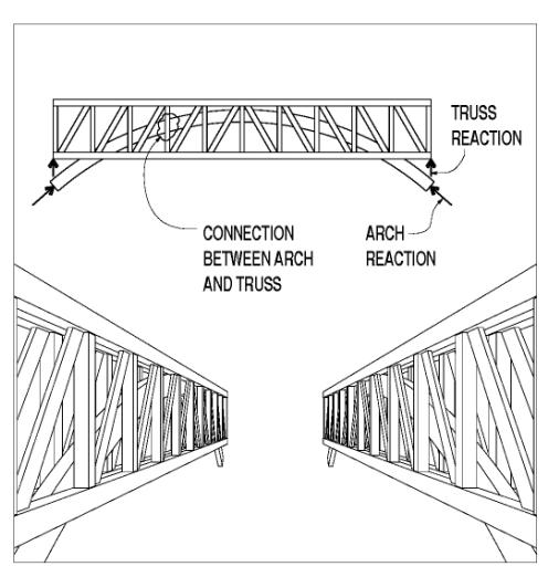
Figure 131. Load sharing between arch and superimposed truss.
Similarly, if the arch is tied and terminates at the bottom chord rather than bearing directly on the abutment, analysis of the structure must be performed carefully to accurately model the behavior of each element. Not only are both the truss and arch primary elements heavily loaded with shear and bending, in addition to the ever-present axial forces in each, but also the connections between the various components usually require the designer to consider myriad local geometry issues.
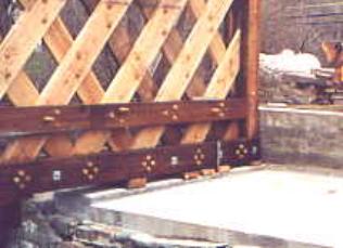
Traditionally framed covered bridges usually contained overhead transverse tie beams at regular spacing along the truss. These beams held the spacing between the trusses, while serving as a basis for lateral buckling resistance for the top compression chords and overall bridge alignment at this level. The details at this connection vary, depending on the preferences of the builder and the situation, but they usually involve notching the undersides of the tie beams where they straddle the top chord. A very common weakness in detailing these notches was the insufficient relish in the tie beam, beyond the outer notch edge and running to the beam end. Large lateral forces in the upper level of the bridge can generate enough axial forces at this connection to shear off this relish, with outward top chord restraint suffering accordingly. Some original builders recognized this problem and would preemptively remove the relish and replace it with a spiked block, loaded on the side grain. This detail is not as stiff as the intact relish, but it is not as brittle, either, and the mechanical connectors can be made as strong as the original wood shear capacity.
The original builders commonly used a direct mechanical connector to hold the tie beam down to the top chord and to keep that bottom dap engaged with the upper face of the top chord. This would also help prevent the tie beam (and roof) from lifting off with high wind forces and from the upward prying induced by transverse knee braces. Vertical bolts commonly were used, down through the tie beam and connected through a single-element top chord, or through transverse hardwood blocks beneath paired top chord elements. Figure 132 shows such a connection. This is a Town lattice truss rehabilitation. The end tie beam relish is noted, along with the bottom block and vertical bolt used to clamp the tie beam to the top chord.
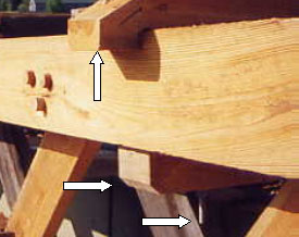
Figure 132. Tie beam to top chord connection. Photo
The connections between the upper lateral force-resisting components and their supporting tie beams almost always involved a mortise-and-tenon connection that allowed the builders to install the lateral braces and then tighten them in place through a pair of opposing wedges. The wedges were installed beyond the tenons on the laterals, in mortises that were cut both completely through the tie beams and further along the tie beams, leaving room for the wedge pairs. An interesting common feature of this connection is the deliberate vertical offset between the mortises for paired laterals in such a way that the laterals actually interfered with each other and had to be bowed vertically as they were installed into their mortises. This prebending meant that the counter lateral bracing was less likely to rattle or work loose and fall out. This offset would often be about 25 mm (1 inch), for a traditionally dimensioned single-lane bridge. Too much offset risked splitting the laterals in a level plane and at the stress concentrations caused by the notched tenon (see figure 133).
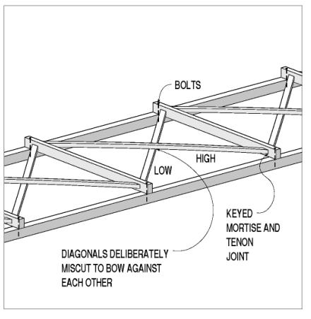
Figure 133. A set of upper braces. Drawing
The midpanel intersection between a pair of the lateral braces as they pass each other may be bolted or not, depending on the practice of the builder. A bolt can help lock the paired X braces together and may prevent one or both from falling out, should the wedges become loose or fall out. The hole for the bolt decreases the element's capacity, but only very slightly. While this decision is somewhat based on individual judgment, most designers would recommend installing a nominal galvanized bolt 19 mm (0.75 inch) at the bypassing lateral braces.
The transverse knee brace connections vary tremendously. They were commonly made with pegged mortise and tenon to the underside of the transverse tie beams, which is still the preferred detail. For trusses with heavy timber vertical members at the panel points, the knee braces are usually connected here with another pegged mortise and tenon. The transverse knee braces in Town lattice trusses, which do not (usually) contain regular heavy timber vertical elements, generally are connected directly to the lattice members, preferably at an intersection between the two lattice layers where the receiving timber is twice as thick. These connections are notoriously weak, especially in tension, and often made only with toe-nailed spikes or lag screws. Rehabilitation projects often stiffen and strengthen these connections by substituting a horizontal bolt through the end of the knee and the lattice intersection. A few bridges contain a supplemental steel rod above and parallel to the knee brace, which provides more strength by engaging both knee braces in a tension-compression system, rather than the traditional compression-only system available with a toe-nailed knee brace. Even this connection detail is ultimately limited by the innate lack of significant strength or stiffness against out-of-plane point loads in the layered lattice planks. Some original Town lattice truss builders and some subsequent rebuilders have countered this intrinsic weakness in the Town lattice truss by adding some relatively heavy (double thickness) vertical planks along the lattice member and in-plane with the inner chords. These posts can provide better material for knee brace mortises, while helping distribute the transverse lateral force more uniformly into the truss. Figure 134 shows an example of added verticals at tie beams in a Town lattice truss.
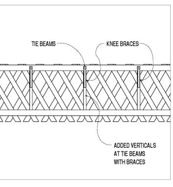
Figure 134. Added verticals at tie beams in Town lattice truss
Since kingpost and queenpost trusses do not normally contain top chord elements in their end panel(s), a rafter plate often was added to support the rafters over the final panel of the truss span. This secondary element may be made from heavy timber or assembled from smaller sections. It may either be continuous, running the full length of the bridge and above the truss top chord, or it may be connected only to the top chord (so that it exists solely in the truss end panel(s)). The rafter plate should be supported by the vertical posts and connected to the tie beams. These three-way connections may be in either separate planes or a common plane, although the latter is far more difficult to detail and to construct, and is often weaker. Figures 135-137 show such a tie beam to top chord connection. The photograph in figure 137 is of the joint that failed when a bridge collapsed due to heavy snow loading. It is immediately obvious that this joint has lost a lot of material from the elements due to the connection in one joint of three elements arranged at right angles to the others. The drawing details in figures 135 and 136 are of the replica bridge.
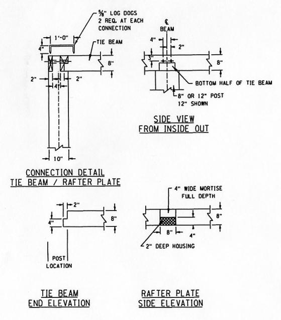
1 inch = 25.4 mm
Figure 135. Tie beam to top chord connection details, first diagram.
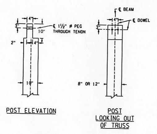
1 inch = 25.4 mm
Figure 136. Tie beam to top chord connection details, second diagram. Drawing.
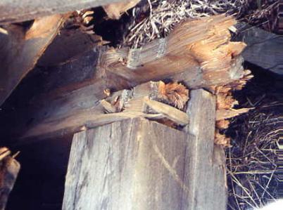
Figure 137. Tie beam to top chord connection details of failed joint.
Deck planks typically are spiked down to the supporting stringers or floor beams. Practical installation considerations and almost inevitable eventual deterioration of these planks dictate that the spikes should be at least 10 mm (0.375 inch) in diameter and should be at least twice as long as the deck plank thickness. Two spikes per plank usually are used at each floor beam connection. Some installers use ring shanks, or similarly modified spikes, to help prevent loosening. The specifier and bridge owner should be aware of this detail, because although these withdrawal-resistant connectors can prevent premature spike head protrusions, replacing the deck planks without also replacing the stringers or floor beams is difficult. In fact, most deck spikes capable of holding the planks down under traffic loads are so secure that removing a plank involves grinding off the connector head and pulling off the plank over the remaining connector shank.
Glue-laminated, longitudinal deck panels, installed above the floor beams, often are connected with proprietary metal connectors that fit into a groove in the floor beams, and are lag screwed into the underside of the deck panels. This connector avoids a hole in the top surface of the deck panel that could allow road moisture to enter the panel material. Some bridge repairers use lag screws (typically countersunk into the top of the decking) in the tops of the floor beams or stringers. This detail also introduces the potential for roadway moisture in the panel material, but this installation allows the work to be performed from above. Some other repairers use bolts that pass completely through the deck and the supporting stringers or floor beams. The hole for this through-bolt can significantly reduce the flexural capacity in the supporting stringer or floor beam, however. Many believe that the potential for roadway moisture penetration below the head of the bolt or lag screw is minor, and therefore choose to work above the deck. The bolt head itself can be an issue, unless countersunk. Therefore, those who choose bolts often use dome head bolts that can be installed without countersinking, although a deck with exposed dome heads presents some serviceability issues. All these connection methods can perform satisfactorily, and cost about the same. The choice among them is based largely on judgment, as long as the various pros and cons are considered.
Longitudinal stringers, when used, are traditionally several panels long. The typical stringer is usually continuous over at least three floor beams. The individual stringers generally lap beyond the adjoining and continuing stringer. In this instance, the stringers are traditionally toe-nailed to the transverse floor beams with heavy spikes. If the stringers are efficient rectangular cross sections with depths greater than widths, diaphragms or blocking is prudent between the stringers as they cross the floor beams; this prevents the stringers from rolling.
As with most other connection details used in authentic covered bridges, this also lends itself to the builder's judgment. Some builders apparently believed that the floor weight alone was sufficient to hold the floor beams in place on the trusses, and that a mechanical connection was not needed between the two, because many bridges do not have a positive connection here. Other builders believed that a more positive connection was at least prudent and responsible, if not commonly necessary to resist any reasonable design loads, be they longitudinal from traffic-caused traction forces with braking or accelerating cars, or transverse forces caused by wind or stream flooding/debris/ice.
At minimum, there should be a connection that prevents the truss bottom chord from sliding out from under a floor beam. This can happen with heavy side impacts from ice floes or debris during floods.
Bridges with more than one bottom chord member often use a vertical bolt down through the floor beam, down through a gap between the chord members, and then through a hardwood block on the underside of the chord to clamp the floor beam to the chord.
For bridges with a single bottom chord element, a vertical bolt through the floor beam and chord occasionally is used. Besides the obvious substantial penalty to the bottom chord net section with the hole, the hole also may permit splash or rainwater to penetrate further and faster into the chord and to accelerate deterioration in the critical bottom chord timbers. Hence, from an engineering perspective, this is not a good connection detail.
Some have installed hardwood pintles (round pegs) on top of the bottom chord; these fit into matching holes in the bottom of the floor beams, achieving results similar to those with a metal rod. A recent example used pintles of 50-mm (2-inch) diameter and 100-mm (4-inch) length, 50 mm (2 inches) into both chord and floor beam. This complex connection helps reduce maintenance associated with the metal rod. A disadvantage of this connection is the inability to inspect the pintle and to examine its condition (or to even know it is there).
A common and simple way to prevent the bottom chord members from shifting along the floor beams is to install a transverse level metal rod connecting the two chords with nuts and washers on the outside of both chords. This rod can draw the chords tight against the floor deck and form a connection with a heavy floor system. This interconnection can ensure that the floor decking will act as a shear diaphragm and help resist transverse lateral loads while maintaining longitudinal alignment. These transverse rods can be positioned evenly along the span; often a quarter-point positioning is sufficient. A detailing issue with this rod is the protruding end of the rod, washer, and nut outside the chord. Because the siding is often attached to the outside chord surface or to a nailer, the nailer must be artificially widened for the siding to cover the ends of these rods. This widened nailer is preferred over simply cutting a hole in the siding that allows the rod extension to protrude through the siding. Although this type of detail was not common on original construction, it has become a popular retrofit in recent bridge rehabilitation projects and is recommended when other means are not employed .
When it exists under a bridge floor, the lower lateral bracing system typically is connected to the sides of the floor beams with mortises and tenons, if it was original to the bridge. A few bridges were built with a double X system, so that there is a mortise connection at the floor beam midspan. This mortise, however, can significantly reduce the flexural capacity of the floor beam and should be considered only as a last resort or if under pressure to match existing conditions.
Some replacement floor systems have installed lateral braces that are connected only with toe-nailed spikes or lag screws, because replacement floor systems often used larger and/or more floor beams. This meant that the original laterals had to be cut to fit, or they were replaced. As indicated elsewhere in this manual, many covered bridge scholars believe that the lower lateral bracing system is unnecessary, at least for the majority of bridges that have floor decking directly above the floor beams. In this instance, the floor connection acts as a deep horizontal diaphragm, in combination with the bottom chords. These very deep beams, generated through diaphragm action in the floor decking, can be so much stiffer than any reasonable system of wedged lateral braces that they nullify the lateral load capacity contribution of the somewhat elaborate bracing system.
For those bridges that have decking on top of stringers that are on top of floor beams, however, a lower lateral bracing system is prudent to provide overall lateral load capacity. The extra plane of intervening elements allows more relative movement, in addition to the opportunity for the vertically positioned stringers to roll over, unless they are substantially restrained with blocking at the floor beams. In this case, the X bracing laterals would be installed beneath the stringers, to the sides of the floor beams.
The connection between the rafters and the truss top chord or rafter plate usually consists of a notch in the rafter (termed a bird's mouth) where it rests on the top of the chord or rafter plate. Typically, the rafter is toe-nailed to the supporting member. Some earlier builders spaced the rafters farther apart than modern codes would allow and included a notch in the top of the top chord or rafter plate to allow an outward thrust-resisting bearing connection. This relieved the stress on the toenails, while being a more complicated joint that further reduced the chord net section. This connection practice is rarely followed today.
The peak of the rafter pairs is treated according to the builder's preference. The rafters may abut at a non-load-bearing ridgepole, and be individually toe-nailed to it. The rafters may simply abut directly to each other with toenails. Some very early builders included a half lap connection at the rafter peaks that may have been toe-nailed or even pegged.
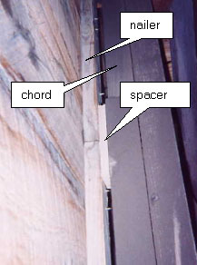
Siding can be attached to the bridge with either nails or screws, depending on local preferences. However, it is important to avoid directly attaching the siding to the truss members, because that large contact area can easily retain moisture and lead to early deterioration in the crucial truss elements. A preferred detail uses nailing (or furring) strips on the outside of the truss element. These nailing strips should be shifted away from the truss element, with short spacers, to further minimize contact with the truss element (see figure 138).
Figure 138. Siding nailers spaced away from truss elements.