U.S. Department of Transportation
Federal Highway Administration
1200 New Jersey Avenue, SE
Washington, DC 20590
202-366-4000
Federal Highway Administration Research and Technology
Coordinating, Developing, and Delivering Highway Transportation Innovations
 |
| This report is an archived publication and may contain dated technical, contact, and link information |
|
Federal Highway Administration > Publications > Research > Structures > Covered Bridge Manual |
Publication Number: FHWA-HRT-04-098 |
Previous | Table of Contents | Next
The rehabilitation of an historic covered bridge is confronted with numerous challenges. The engineering involves issues unfamiliar to many of today's practicing engineers. The relatively few, and geographically dispersed, covered bridge construction projects in modern times often involve contractors with limited experience with the nuances of covered bridges. Three bridges in Delaware County, New York have recently undergone extensive rehabilitation. This paper discusses several of the challenges associated with one of the bridges. Although not funded by the National Historic Covered Bridge Preservation Act (the third bridge was), the work was performed to the same standards as required by that program.
Hamden Bridge-130-foot (39.6 m) span Colonel Steven Long truss configuration:
The Hamden Covered Bridge, built in 1859, spans the West Branch Delaware River near the hamlet of Hamden in Delaware County, New York. The County owns three covered bridges and began a major rehabilitation of all three bridges in the past several years. This bridge was the second of the three to be rehabilitated.
The bridge is supported by truss configurations patented by, and named for, Colonel Stephen H. Long in 1830. The all-timber truss is similar in nature to a multiple kingpost but has counters in each panel. The popularity of the truss was quickly overshadowed by the use of metal vertical members in a truss configuration patented by William Howe in 1840. Hence, there are only about 25 remaining covered bridges supported by Long trusses.
During its existence, the Hamden Covered Bridge has been rehabilitated several times, the last time in the 1970s. By the mid 1990s, the bridge was racked and many of the verticals near the end of the bridge exhibited crushing and bending distortions, indicating significant overstress. Figure 177 depicts a pre-construction view of the bridge.
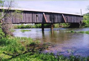
Figure 177. View of the Hamden Covered Bridge prior to work in 2000. Note the mid-span timber bent added in the 1970s to help support the sagging trusses. Also note the external top chord braces.
The West Branch of the Delaware River can rise rapidly during times of heavy rain. It is also a highly regulated waterway and trout stream. Therefore working over the water would represent special challenges. Accordingly, the contractor chose to relocate the span to its southern approach roadway section for the reconstruction process. The construction documents did not object to such a move. The documents required engineering sketches and calculations addressing the proposed means for support of the bridge during its reconstruction. Hence, engineering information was required for the relocation.
The contractor had previously completed the successful reconstruction of another covered bridge owned by Delaware County (the Downsville Bridge-a 170-foot- (51.8 m) long bridge built by Robert Murray, who also built the Hamden Bridge), also using a Long Truss configuration, but supplemented with a stiffening arch. That project had gone well, and the contractor had demonstrated great skill and care with that work. His company has an excellent reputation for construction work, including historic repairs of timber structures.
The contractor proposed to relocate the bridge using a pair of heavy cranes, one on each shore, but had not presented engineering support for the work. We decided to allow the move to proceed, albeit with some trepidation. Unfortunately, the move culminated in an accident that effectively broke the bridge into two pieces and dropped them into the river (see figure 176).
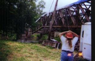
Figure 178. How NOT to relocate a covered bridge for repair work.
Fortunately, no one was hurt during this accident and, ultimately, the damage to the bridge did not involve many components beyond those already identified for replacement for other reasons. We, the County, shared in the blame in that we did not insist on the engineering support prior to the work.
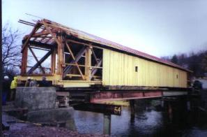
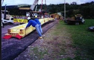
The reconstruction of the bridge proceeded through the summer and fall. When ready to relocate the bridge back to its reconstructed foundations, the County insisted on the use of a roller system supported on false work. The County provided and installed the majority of the false work system while the contractor provided a specialty subcontractor to oversee the relocation. That work went without a hitch (see figure 179). This system proved to be a good way to relocate a covered bridge.
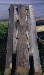
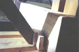
This style of truss contains three separate bottom chord sticks with a pair of vertical posts between them. The members are shouldered at the connections to facilitate load transfer (a "shoulder" is a notch cut into a face of a member that joins another at right angles). The chord members contained a larger central stick of 9 inches by 13 inches (229 mm by 330 mm), flanked by smaller sticks of 5 by 13 (127 by 330). The trusses were originally built of local Eastern Hemlock with stick lengths of up to 50 feet (15.2 m) (much larger than is readily available today!). The traditional form of splice for such an arrangement at the time of its construction uses a splice termed a "Bolt-of-Lightning" detail (see figure 180).
Unfortunately, the proportions of this truss and its joinery are such that the splice is substantially weaker than the main members. Any potential alteration of the sizes of the bottom chord members would require related changes in other truss members and was considered an inappropriate alternative. Based on work undertaken earlier at the Downsville Covered Bridge, it was decided to replace the bottom chords with three one-piece glue-laminated members (that's right--130-feet (39.6 m) long in the Hamden Bridge; 170-feet (51.8 m) long in the Downsville Bridge!). The fabrication and delivery of such beams was impressive in its own right. Yet, these one-piece chords eliminated the need for splicing and the problems associated with it.
The Hamden Covered Bridge has had external top chord bracing supports, similar to some other bridges in the area. Some refer to such bracing as buttresses; some of us have a more derogatory term-elephant ears-since in my opinion, they are evidence of an unwillingness to make the internal bracing system do its job. It is unclear if these external braces were original at the time of construction, or added later when the bridge exhibited distress (refer back to figure 177 and note the external braces).
The original roofline is relatively shallow on the Hamden Bridge and offers little room to improve the internal bracing system. Again, in large part following the work performed at the Downsville Bridge, the roof of the Hamden Bridge was removed to allow the replacement with a more conventional sloped roof with more space to install a substantial internal bracing system. The tie beams were joined with oversized rafters and knee braces of sufficient size and connection strength to maintain the stability of the bridge.
Prior to this rehabilitation of the bridge, several of the members at the ends of the trusses exhibited significant distortion and overstress (refer to figure 183).
Figure 183. Diagonal to post connections at the top chord indicating significant overstress.
If you look carefully you see that the top of the vertical post is cracked above the upper right bolt. Also note the general bend of the vertical to the right. The Knee Brace is in the foreground connecting to the Tie Beam just out of the top of the photograph. The pair of main Diagonals is on the right and the Counter is on the left. The reconstruction of the bridge replaced these split posts with heavier members.
One of the interesting aspects of the patent application of Colonel Long was the provision of wedges at the connection between vertical post and chord. Quite a bit has been written about these wedges. They have been attributed as the precursors of post-tensioning systems that have become commonplace in the second half of the 20th Century. An oft-used diagram to demonstrate their function is with a two-panel truss. It is fascinating to delve into this issue a little more and find that while the two-panel truss can be manipulated to demonstrate a post-tensioning effect from the wedges, a truss with more panels cannot support this concept.
Instead of pursuing this aspect further, this writer prefers to consider the other advantages of the wedges. The interface of the vertical members and chords is one with very high side-grain compression in the vertical against end-grain compression in the chord. These forces are the direct consequence of the horizontal component of load in the diagonal members as they are transferred to the chords in axial load. A thorough review of the stresses of the joints of the Hamden Bridge indicates that the wedges play an important role in distributing the stress to the post over a greater area to effectively reduce the side-grain compression. In this writer's opinion, it is conceivable that Colonel Long recognized the advantage of the wedges in this way.
However, there is another twist to this issue. Some Long trusses were built with wedges in both top and bottom chords, while others (like Hamden) were built with wedges only in the bottom chord. The side-grain bearing issue is just as important in the top as bottom; hence, the posit that Long recognized this strength is counteracted by leaving them out of the top chords. The wedges are easily visible in the top chord connections, while the bottom chord wedges are hidden beneath the floor beams and a careful inspection from below is necessary to observe them.
It would be interesting to inspect all remaining Long truss bridges (there are only about 25 extant covered bridges that are supported by some variation of a Long truss) to compare the use of wedges against their date of construction to see if the use evolved. Of course, it must be recognized that the actual builders of the bridges could have individual impressions of the merits of the wedges, contrary to what may have been intended by Colonel Long. Hence, such an exercise, while interesting, may not lead to a clear answer to this issue.
In any event, we decided that the merits of the wedges for the reduction in post stresses were substantial and we introduced wedges in the top chord of the Hamden Bridge during its reconstruction. No attempt was made to use the wedges to affect the shape of the truss.
The joints of a Long truss between vertical post and chord member usually contain a single or occasionally two transverse bolts (refer back to figure 183). Recall from the earlier discussion that the transfer of force from one member to another involves a double shoulder detail. That is, the horizontal shoulders of the post mated against the horizontal edge of the chord transfers vertical load through the joint. (This is the primary means of keeping the floor from falling from the bridge-the floor beam sits atop the chord, which is held from sliding down the post by the shoulder in the post.) Similarly, the vertical shoulder in the chord mated against the vertical edge of the post transfers the horizontal component of load from the diagonal through the post to the chord.
When one considers the strength of the bearing surfaces of the shoulders with the potential shear strength of the bolt, one finds that the bolt does not contribute much to the strength of the joint. However, the bolt represents a potential failure mechanism of the joint, as described hereafter.
In many instances, timber is placed in a truss after some initial drying. Yet, during the life of the truss, the members will continue to change sizes due to moisture retention in times of very high humidity (or in the event of a leaking roof directly above such a joint) or additional drying. When the joint must transmit high stresses (typically at the few end panels of a truss), the post tends to deform and bend under the high stresses. If the bolt has been installed in a typical hole (one only slightly larger than the bolt), side-grain bearing (and its concurrent tension perpendicular to grain) can develop at the bolt. Since timber is relatively weak in such side-grain tension, a split often develops from the bolt through to the end of the member.
Accordingly, the reconstruction of the Hamden Bridge involved an extra step to ream the holes of the transverse connectors after the initial reconstruction of the trusses and before the bridge was released from its false work. Such reaming will allow some future change in sizes of the post from swelling and/or shrinkage and distortion from loading without the imposition of significant side grain tension. The same considerations are involved in many types of timber joinery typical of covered bridge construction.
The counters of a Long Truss (those members of the "X" in each truss panel that are opposite of the main diagonals) are used to provide resistance for the passage of heavy vehicles (or unusual snow loading); the discussion hereafter is limited to vehicles for clarity). Especially for the panels nearer the center of the bridge, the dead load in the main diagonals can be less than the load imposed by the passage of a heavy vehicle. The net result for some positions of vehicular loading is that the force in the main diagonal due to the weight of the bridge can be counteracted by that caused by the vehicle's weight, that is, the main diagonal can actually become "loose", since it is not connected for tension. Hence, the counters assist the main diagonals by offering compression resistance to prevent the distortion and potential failure of the truss panel.
Yet, the potential load in the counters is dependent on their initial installation. The counters are not required to support dead loads, so when no vehicles are on the bridge, the counter could technically be "loose". However, if they were loose under the no-load condition, then they could fall out, or work loose, after repeated structure loading by vehicles.
So the practical question when dealing with counters in these types of trusses is, how tight at initial conditions? This writer is unaware of any documented guidelines and relies on general structural engineering instincts. The load in the counter is typically controlled by manipulation of opposing ("folding") wedges installed at either the top or the bottom of the counter. The harder one pounds the wedges into place, the more load is forced into the counter. After tightening the wedges until the counter feels "snug," it is then important to prevent the wedges from loosening. We used heavy wood screws in the wedges to hold their position and to facilitate future retightening after the bridge had served for awhile and had attained a typical moisture content. Many extant historic covered bridges contain similar wedge details without screws and often seem to stay tight strictly due to friction in the wedges. However, reports of counters (and even main diagonals of some trusses) falling out of bridges are also common.
So what is the definition of "snug"? In the context intended herein, a snug counter is one that cannot be moved sideways much when firmly shaken by hand. This test is appropriate prior to the installation of any screws or other fasteners in the wedges. If such a shaking dislodges the wedges, then the counter is probably not tight enough.
The diagonal members of the upper lateral system are typically connected to the Tie Beams with mortise and tenons (a mortise pocket is cut into the side of the Tie Beam; the end of the diagonal is cut to a mating tenon). Folding wedges are used here also, behind the end of the tenons, within the mortise, as a means to maintain the diagonals with a tight fit. It is quite easy to move the top of the trusses laterally by driving the wedges more. When the chords are straight and the laterals are tight, then the wedges should be locked; again we use heavy screws.
Yet, there is another trick that may not be so obvious to the casual observer. Many of the original builders of covered bridges positioned the mortise pockets in the Tie Beam to be vertically offset from what they would be for straight lateral members. In this way, the opposing diagonal members in each panel had to be forced vertically to fit into the mortise (assembly of such a system is not easy to make in the field!). Hence, even if the end folding wedges work loose, the bowed diagonals tend to hold each other in position against simply falling out. Routine inspections of the structure will likely discover loose wedges prior to a potentially life-threatening accident such as a lateral falling into the path of an oncoming vehicle.
The timber work was completed by the contractor in late 2000 after the asphalt plants closed for the season. The County completed the approach grading and asphalt work, installation of guide rail system, and slope protection system in June, 2001 and the bridge was reopened to traffic on July 2, 2001. The contract was for $558,000 and the County incurred approximately another $150,000 for the work cited above along with the costs of engineering and inspection support.
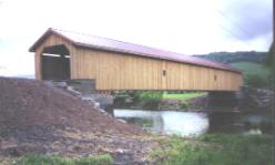
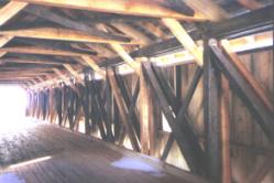
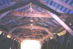
Figure 187. Final inside view. Note the lighter-colored replacement members.
Acknowledgment
David Fischetti, P.E., Cary, NC, performed the initial engineering on this project.

