U.S. Department of Transportation
Federal Highway Administration
1200 New Jersey Avenue, SE
Washington, DC 20590
202-366-4000
Federal Highway Administration Research and Technology
Coordinating, Developing, and Delivering Highway Transportation Innovations
 |
| This report is an archived publication and may contain dated technical, contact, and link information |
|
Federal Highway Administration > Publications > Research > Structures > Covered Bridge Manual |
Publication Number: FHWA-HRT-04-098 |
Previous | Table of Contents | Next
The existing Brown's River Covered Bridge, built in 1837, served until 1965 when it was bypassed and abandoned. Some repairs were performed in 1975. In 1987, again in bad shape, the bridge was removed from its foundations and set on cribbing in a nearby field. Work on covered bridges was not as popular at that time, and the removal was performed with power provided by oxen and capstan. The effort to remove the bridge from its foundations was filmed as part of a Public Broadcasting Service (PBS) documentary featuring Milton Graton (the late renowned covered bridge reconstruction specialist). Graton began repair work, but funds were exhausted before the work was completed.
The bridge sat idle in the field overlooking its foundations, awaiting additional funding to finish the project. A long effort chasing grants culminated in funding via the Intermodal Surface Transportation Efficiency Act of 1991 and supplemental funding in 1999 from the Transportation Equity Act for the 21st Century.
With sufficient funds now available, a contract was let for final repair of the bridge and its abutments and resiting the structure to its river crossing. Bridge repair work began in early 2001, and the bridge was relocated on July 20, 2001 on heavy moving steerable dollies, towed by large wrecker trucks. Back at its original site and adjacent to a modern bridge that supports vehicular traffic, the covered bridge serves only pedestrian traffic.
A number of issues caused this project to be especially challenging. From an engineering perspective, the lack of sufficient funds resulted in more reliance on the contractor to handle issues as they came up without thorough plans in advance. Multiple telephone conversations ensued during the work along with a few site visits. Several of the issues are discussed below.
Unfortunately, the repairs that began in 1987 were not completed, and the bridge sat on cribbing for 13 years. During that time, the cribbing suffered some differential settlement that racked the bridge. Although it is not certain that this was present in the 1980s, two-thirds of the top chord of the south truss had been attacked by powder post beetles when the project began. The wood shingle roof installed in the 1980s was now leaking. The ends of the bottom chords had been replaced, and large bolster beams were positioned beneath the chords. There was no direct splice of the chords, and the connection of the bolsters was judged to be inadequate to restore the integrity of the bottom chords without additional work. Several damaged, broken, or missing components of the bracing were not yet addressed.
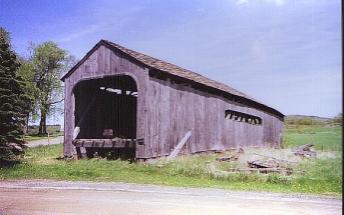
Figure 203. As the bridge sat for 13 years.
The abutments remained as they were when the bridge was removed. The upstream corner of the east abutment was separated from the stem, and a section of stone wall along the wing wall was near collapse condition. The caps and backwalls awaited replacement to accommodate the rebuilt superstructure.
At the time of the final push, funds were extremely limited, yet the 13-year effort to obtain funds had been extraordinary. Recognizing that the bridge would not have to support vehicular traffic and that pedestrian loading would be limited at this rural location, the engineering was to include:
The Historical Society retained another local engineering firm to prepare a complete contract bid document including bid forms, agreement, bond requirements, and other standard information.
While this situation is not desirable, and should not be undertaken by inexperienced personnel, this project approach proved to be successful in this instance, in large part due to the close working professional relationship among the contractor, engineer, and owner's representative.
One of the important issues related to this work was the need to replace truss components while attempting minimal removals. The top chord of the east truss was originally built in three pieces with a special joinery connection (refer to figure 204). The chords were positioned down onto tenons from the ends of the posts. Replacing the chord, therefore, required the temporary support of the rafters and tie beams to raise them out of the way.
Figure 204. Replacement top chords.
While replacing the top chord, a section of substantial rot was found in the top of one post (refer to figure 205). No external evidence of such deterioration was visible. Yet, the post either had to be partially or completely replaced. The decision was made to completely replace the post. A couple of other posts were also replaced to better address previous partial repairs that were judged to be insufficiently connected.
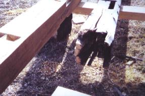
Figure 205. Hidden rot inside top of old post.
Straightening the structure as a consequence of these rather extensive repairs and long-term cribbing differential settlement led to discovery that the existing knee braces would have to be replaced to fit the restored geometry.
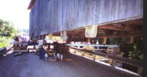
One of the features often added by Mr. Graton in his restoration of scores of covered bridges was bolster beams beneath the ends of the bottom chords. These elements project beyond the front edge of the abutment seat and serve to stiffen the ends of the truss. However, the bolsters added to this bridge were especially large and long-three panels long, in fact (refer to figure 206). Bolsters are usually added separately from the chord, so that they do not act as truss members; instead they supplement the behavior of the truss by adding bending capacity in addition to the truss behavior. The existing bottom chords had been severed at sound material away from the rotted end portions, in the second or third panel from the end. Instead of installing a tensile splice to connect the new ends to the original portions, the large bolsters were connected to the chords by a few vertical bolts. It may well be that these connections were not completed at the time work was abandoned. Figure 206 also shows the arches that were terminated at the bottom chord without extensions to the abutment.
(Photo courtesy of Joseph Nelson)
Figure 206 Bridge moved, but not down off temporary cribs.
Project managers inherited a situation in which the existing bolsters were expected to serve as replacement bottom chord elements being subject to axial loads, in addition to their normal bending behavior. While the bolsters were no doubt large enough to accommodate such expectations (114 by 406 mm (4.5 by 16 inches)), they had not been connected in a way to adequately transfer the loads across the butt connections of the bottom chord.
Accordingly, we devised a plan to install a series of timber shear blocks at the interface of the bottom of the chord to the top of the bolster. In combination with the bolts, the additional shear blocks would provide an acceptable capacity. The plans called for rectangular 100-mm- (4-inch) high by 200-mm- (8-inch) wide hardwood blocks to be inserted into new pockets cut into the interface from the side. The contractor had considerable experience using round wooden dowels to accomplish the same effect and believed the round dowels would serve better in this instance. Following extensive conversations and additional analytical evaluations, it was decided to allow the use of the round dowels (refer to figure 207).
Figure 207. View of shear dowel reinforcement.
Figure 204 clearly shows that the arch elements have been cut off at the bottom of the bolster beams. In a classic Burr arch, the arch elements project down past the bottom of the chords to bear against the abutment. In so doing, they can true arch behavior to augment the truss behavior of the timber structure. However, in those bridges that have had an alteration to terminate the arch without bearing on the abutment, or if the bridge had been built originally like that, the arch cannot offer much assistance to the truss. Such structures are often referred to as modified Burr arches.
Further, the connection between arch and truss is often a single bolt element at the intersection of the center of the vertical elements of the truss and the centerline of the arch. It is common to observe that these bolt elements are deformed from the excessive forces attempting to connect the two types of systems together. This is another reason that makes the analysis of such combination structures especially challenging.
The arch components on this bridge are comprised of a pair of solid-sawn members that straddle the truss. As the arch in the center of the bridge comes lower toward the bottom chord as it traverses toward the end of the bridge, it has been deflected outward in this bridge to pass the bottom chord. Hence, the gradual appearance of the arch in figure 204. Some bridges are built such that the arch components are interrupted at the bottom chord with a splice so that the arch remains in the same plane as the bottom chord.
The original stone abutments had been faced with concrete, as is common. While the quality of concrete facing is not great, the bulk of it seemed sound and stable. There was no evidence of deep-seated foundation failures; therefore it was quickly decided to retain the bulk of the abutments. New caps were required due to a change in the floor configuration (the trusses originally extended beyond the floor; therefore, the concrete backwalls had jogs at each corner). Further, the north corner of the east abutment had separated from the main stem concrete and needed to be replaced. The connecting wingwall was dry-laid stone that had shifted and was on the verge of collapse. A roadway drainage pipe discharged at a point at the beginning of the stone wall and was contributing to its demise. A review of the roadway drainage situation indicated that a cross culvert could be installed in the roadway uphill of the covered bridge abutment. This would allow the removal of a major portion of the stone wingwall and regrading to fill in the ditch in front of the wall. The corner of the abutment was removed and recast on new concrete stepped footings to connect to the rest of the abutment stem concrete.
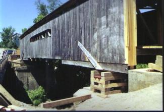
New thick concrete pads were cast atop both abutments to help knit the combination of original stone and concrete facing together. Backwalls and short wingwalls were then cast with dowels into the main pads. The resulting concrete treatment was economical and should serve well for a long time (refer to figure 208)
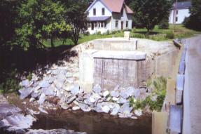
Figure 208. Reconstructed east abutment.
The bridge had had new wooden shakes installed in the 1980s, but the roof was leaking quite badly. After considering the alternatives, it was decided that the roof should be replaced. Vehicular traffic tends to vibrate a bridge enough to cause snow to slide off faster than bridges closed to traffic. Since this bridge was to remain open only to pedestrian traffic, it seemed prudent to use metal panels rather than wooden shakes or shingles.
Without question, the relocation of the bridge garnered the most attention. A pair of steerable dollies was located at each end of the bridge. The power to move the bridge was provided by winches from large wreckers. The roadway is quite steep leading down to the bridge site, and the process involved parking the tractor uphill of the bridge and releasing the cables to their limit, then moving the wrecker to start the process again. The far end of the bridge was hooked to a separate wrecker that provided the steering guidance. It was able to hold the bridge in position with its brakes while the rear wrecker was relocated (refer to figure 209). Upon reaching the low point in the profile, the far wrecker took over and pulled it into place.
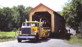
Figure 209. Underway on dollies.
The close proximity of the bypass bridge was very convenient, in that the covered bridge on the steerable dollies was pulled across the bypass bridge to align it on the abutments. Then cribbing and skid beams were installed beneath the bridge superstructure to allow it to be winched sideways over the top of the guiderail to the rehabilitated abutments. An interesting challenge involved the relative skew between the two bridges (they are not parallel). Therefore, the end of the bridge closest to the old location was supported on a single heavy roller nest at the centerline of the bridge to allow it to act as a pivot when the other end was winched sideways. In this way, the bridge was moved differentially to align it with its bearing areas. The movers used a swivel roller system beneath each corner at first. Then, to rotate the bridge to accommodate the skew between the respective bridges, the pair of rollers was replaced with a central unit at one end to provide a pivot point.
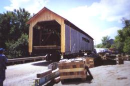
Figure 210. On top of the bypass bridge-ready to be slid sideways.
Once in the proper location, the bridge was too high and had to be lowered into place by a repetitious process of supporting the weight on the jacks and then removing cribbing, then releasing the jacks to the new lower position. The move from the field to the bridge's original location over the river was accomplished by midafternoon. The lowering process was not completed until the following morning.

