U.S. Department of Transportation
Federal Highway Administration
1200 New Jersey Avenue, SE
Washington, DC 20590
202-366-4000
Federal Highway Administration Research and Technology
Coordinating, Developing, and Delivering Highway Transportation Innovations
 |
| This report is an archived publication and may contain dated technical, contact, and link information |
|
Federal Highway Administration > Publications > Research > Structures > Covered Bridge Manual |
Publication Number: FHWA-HRT-04-098 |
Previous | Table of Contents | Next
The City of Guelph Parks Department's extensive network of bike and walking trails was the pride of the city of Guelph, Ontario, but it had one major flaw: the Speed River cut the trail system in half, forcing long detours. The city and the Timber Framers Guild struck a deal to solve this problem-at the Guild's first international conference in June 1992, its members would span the river with a pedestrian bridge. And they would do it in style, building a 44-m- (144-ft) long Town lattice covered bridge. The project was notable for several features, including its ambitious construction schedule, crew size, coordination, and innovative frame details.
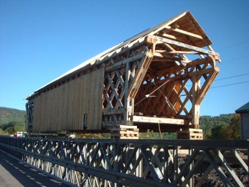
Contrary to expectation, the 4788 Pa (100 psf) pedestrian live load on the bridge deck proved a more stringent condition than typical highway loading. Fortunately, road width was not an issue in Guelph. Centerline truss-to-truss distance was set at 3.5 m (11 ft, 10 inches), yielding a floor joist span of 3.2 m (10 ft, 4 inches), allowing use of full-size 5 by7 select structural Douglas Fir joists 609 mm (24 inches) on center. The Town trusses measured a relatively deep 4.6 m (15 ft, 1 inch) high (out-to-out on the chords) and used 45° lattice with 3 by11 web members on four foot centers clasped by the typical chord layout: double chords top and bottom, each strand built up of two layers (3 by 10 upper, 3 by 12 lower). Lower chord stock was cut to the maximum length available from the supplier (7.3 m (24 ft)) to minimize end joints in the tension chords. Figures 212 and 213 depict views of the bridge.
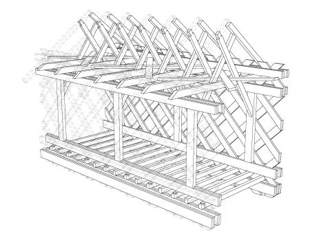
Figure 212. Bridge perspective view.
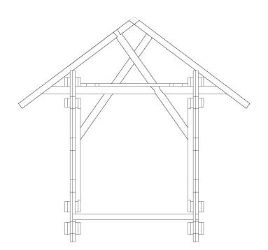
Figure 213. Typical bridge section.
The bottom inside upper chord lams were oversize (3x12), as were their counterparts in the lower chords (top inside sticks at 3x14), creating 3x2-inch grooves running the length of the bridge. These slots received stub tenons on the ends of 12x6 posts set on 3.7-m (12-ft) centers, with the columns also pinned to adjacent lattice crossings, thus fixing them securely to the trusses. The posts, in turn, served as spring points for 4x8 passing braces, with each brace rising to the rafter on the far side, along the way crossing tie beam and opposing brace, yielding four joints per brace:
| Location | Connection |
|---|---|
| Brace-to-Post | Pinned Blind Mortise and Tenon |
| Brace-to-Tie | Hourglass Half Lap |
| Brace-to-Brace | Pinned |
| Brace-to-Rafter | Barefaced Lap Dovetail |
This combination of posts woven into the web and passing braces with multiple connections went a long way toward curing the notorious weakness of Town bridges-their tendency to wrack in cross section.
The Guelph project introduced covered bridge construction to many members of the Timber Framers Guild through a unique design and construction process managed by a six-person bridge club. The Guild contracted with the City of Guelph to fabricate the bridge. A professional bridge builder was hired to supervise. Apart from this builder and the small crew, all bridge workers were volunteers, donating their time to the Guild.
Canadian authorities had decreed that a cribbing tower could not be built in the river to support temporary girders for a traditional bridge rollout, so two big cranes 227,273 and 363,636 kg (250- and 400-ton) hydraulic) were planned to set the bridge on its abutments. Because cranes could only take the 68,100-kg (150,000-pound) bridge the last few feet, the Guild crew was required to first raise the two 18,160-kg (40,000-pound) trusses, build the floor and roof, then roll the bridge out, cantilevering it over the river for the short flight home. All the building and rigging work was slated to be completed with hand tools over the 5 days of the Guild Conference, a daunting prospect. However, a capable and determined crew of 400 was ready to do the job.
Chords and lattice had been laid down by advance teams before the conference. On the first day, the crew was given 44.45 mm (1.75-inch) pegs to drive, rapidly turning the two 45.75-m- (150-ft) long timber piles into functioning bridge trusses. To raise the trusses, the crew was divided into pushers and pullers. The former would lift the truss, first by hand, then with the aid of dozens of traditional pike poles. Meanwhile the pullers would do the bulk of the work, hauling on 25.4-mm (1-inch) manila lines reeved through six sets of triple-sheave block and tackle-rigged to temporary derricks built of phone poles loaned for the purpose (see figure 188).
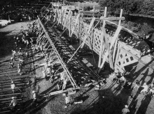
Figure 214. Raising the trusses.
The rising trusses came against the phone poles and were then trued-up plumb, level, and even with each other. Floor joists snaked through the lattice, and two layers of flooring were nailed down at 45° to the joists and 90° to each other (for wind resistance). Meanwhile, teams built and set 15 roof trusses and intermediate X-braced common rafters on 1.2-m (4-ft) centers.
With floor, flooring, and roof structure complete, the bridge was jacked up and rolled toward its moorings on veneer core rollers using rails made from reused blocking, bed timbers, and derrick material with motive power once again supplied by the builders via block and tackle. To save time and weight, installation of roof nailers and shingles was deferred until after the bridge lift. The work was completed on schedule.
After the Speed River Bridge project, many participants have sought additional opportunities for covered bridge construction and preservation, and bridge work is gradually reasserting its status as a staple of the timber frame repertoire.
Sometime in the 1880s, a pair of inline Town lattice bridges was built across the Ottauquechee River just above its confluence with the Connecticut River. By taking advantage of an island in Ottauquechee, the builders saved 30 m (100 ft) of bridge. The twin bridges carried traffic along Mill Street until 1938, when the southernmost span was washed away in a hurricane. It was replaced with a steel-and-concrete bridge the following year.
By the mid-1990s, the replacement bridge was at the end of its useful life; girders were badly rusted, and the concrete was spalling away. By contrast, the 100-year-old surviving covered sister still looked and worked like new. The close proximity of and contrast between the two spans made them ideal for a covered bridge revival, illustrating the advantages of covered bridges when measured by longevity, life cycle cost, environmental impact, resource efficiency, and beauty. The people of Hartland, VT wanted a new covered bridge, and the Vermont Agency of Transportation had scant basis for objection, because the Mill Street neighborhood was already accessed via covered bridge.
The new span would emulate the surviving lattice bridge. Its relatively short span (19.8 m (65 ft) clear, 24.7 m (81 ft) overall) and tall trusses (4.9 m (16 ft) outside chord height[1]) meant that there was no question as to the adequacy of the trusses. On the other hand, AASHTO HS 15 highway loading presented a challenge, given the 5.2-m (17-ft) joist clear spans. To meet this standard, 7x14 select structural hickory joists were specified, 0.6 m (2 ft) on center, with 10x4 select structural oak or hickory planking secured with 63.5 mm by 203.3 mm (2.5 inch by 8 inch) lag bolts per plank per joist.
The builder adopted a novel strategy to counter wracking, using 16 Larch ship's knees spaced at 3.7-m (12-ft) intervals, bolted and shear-block to upper chords and tie beams, stiffening the bridge without obstructing vehicle passage (see figure 215). Note the ship's knees in the photo; these increased inside clearance, while still providing a good bracing element.
Figure 215. Hartland Bridge on the move.
The project was scheduled for construction during the summer of 2000, but delays in upgrading the abutments postponed completion to the following year. Having already obtained much of the spruce timber for the trusses, the builder did not want to let it sit and twist, and secured permission to assemble the bridge frame in the town park a quarter of a mile from the river crossing. In August of 2001, the completed span (without the roof) was rolled down the road and set in place (see figure 216).
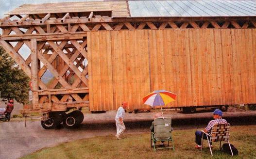
Figure 216. Observers watching a bridge move past.