U.S. Department of Transportation
Federal Highway Administration
1200 New Jersey Avenue, SE
Washington, DC 20590
202-366-4000
Federal Highway Administration Research and Technology
Coordinating, Developing, and Delivering Highway Transportation Innovations
 |
| This report is an archived publication and may contain dated technical, contact, and link information |
|
Federal Highway Administration > Publications > Research > Structures > Covered Bridge Manual |
Publication Number: FHWA-HRT-04-098 |
Previous | Table of Contents | Next
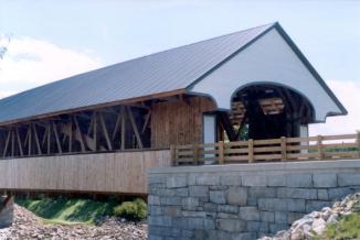
The Smith Covered Bridge over the Baker River in Plymouth, NH, is a traditionally framed, two-lane-wide timber covered bridge that is designed for AASHTO HS20 loading. It was constructed in 2000-2001, and it is located on the site of a load-posted, one-lane covered bridge that was built in 1850 and destroyed in an arson fire in 1993. The decision to replace the old bridge with the new covered bridge was a compromise between local sentiment for replicating the old bridge and the need for a two-lane bridge without load posting as determined by the New Hampshire Department of Transportation (NHDOT). NHDOT selected a consultant design team, and the project followed the typical design-bid-build process.
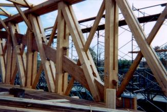
The new bridge has many similarities with the old bridge, but it is also different in many ways. The main trusses of the old bridge were in general accordance with some of Stephen Long's 19th century patents and were assisted by supplemental arches, as are the new trusses. The arches of the new bridge are sandwiched within the truss plies similar to the method used in the Blenheim Covered Bridge that was designed by Nichols Powers in 1854. (Blenheim Covered Bridge is a double-barrel bridge that is considered to have the world's longest span for a covered bridge). In this way, the arches and trusses can share the burden of carrying the gravity loads. In contrast, if arches are fastened to the sides of the trusses, (as is typical of Burr arch/truss design and as was done in the old bridge because those arches reportedly added a few years after the initial construction), then it is much more problematic to ensure adequate load sharing.
For the new bridge, truss depth is dictated by the geometric design parameters of an arched portal opening and a 4.4-m (14.5-ft) minimum clear height for the full 7.3-m (24-ft) deck width. The combination of truss depth, span length, and design loading requires very large trusses. As a result, structural glue-laminated timbers (also known as glulam) have been used for the truss members. In contrast, if solid-sawn timbers had been used, then the truss members would have been much heavier and larger in cross section due to the greater variability and generally lower reliable strength of solid-sawn timber compared to glulam. The trusses of the new bridge are relatively deep and thick for a covered bridge carrying roadway traffic, and in this respect they are more akin to the large timber trusses that were used in the past for some railroad bridges.
In most cases, joinery details of the new bridge use shouldered wood connections and hardwood wedges. This is evident in the main trusses and is consistent with Long's patents. Use of modern metal fasteners for the truss node connections was not feasible, because there was not enough room to squeeze in the many fasteners that would have been required. In most cases, bottom chord splices are in general accordance with Long's ideas.
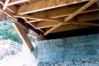
Design of the areas where the arches pass through the bottom chords was particularly problematic. In these areas, sistered timbers and split ring shear connectors provide continuity to the second and third chord plies. The floor beam in this area cannot extend over all four-chord plies due to arch interference, so a steel fabrication is used to transfer the floor beam reaction into the arch without distressing the innermost chord ply. The sidewalk framing is also more complicated in this area because of the shortened floor beam.
Roadway width and design live loading dictated the 762-mm (30-inch)-deep glue-laminated timber floor beams. Solid sawn timber floor beams were not feasible for the bridge due to the required floor beam depth. The floor beams rest on top of the bottom chords and are located at the quarter points of the truss panels (i.e., 1.75-m (5.75-ft) spacing on center). The glulam deck is 171.45 mm (6.75 inches) thick and has a 76.2-mm (3-inch)-thick oak plank wearing surface.
All truss, arch, floor beam, deck, and lateral bracing members are glulam timbers manufactured from Southern Pine. Roof framing and most other miscellaneous wood members are solid-sawn Southern Pine timber or lumber. Southern Pine was selected because of its relatively high strength and because of its ability to receive pressure preservative treatment without the need for incising. All main wood framing components below the level of the roof eaves were pressure preservative treated with pentachlorophenol. The wood siding is single layer vertical board siding on the sides and horizontal clapboard siding on the portals. The roof surface is corrugated metal, and it is supported by 4x4 lumber purlins that are fastened on top of the rafters. To reduce the potential for destruction by fire, a fire detection and alarm system has been installed, and much of the superstructure has received fire retardant clear coating.
The substructures consist of pile supported, reinforced concrete abutments with 0.3-m (1-ft)-thick ashlar granite facing. The abutments not only support the gravity loads of the superstructure, but also the horizontal loads from arch thrust. The granite facing was added to match the appearance of the original abutments, one of which has been preserved immediately adjacent to the new bridge. The deep bedrock and sandy soils at the bridge site necessitate the many long battered friction piles to reduce the potential for scour problems and foundation movement.
Detailed shop drawings showing all wood fabrication notches, mortises, tenons, and fastener holes were prepared for each glulam member. Most of the many required notches, holes, etc. were made in the glulam fabrication plant. Portions of the superstructure were temporarily assembled at the fabrication plant to ensure proper fit. Individual pieces were then transported to the site and reassembled in place on false work that was erected in the river. Most of the members were brought in a piece at a time using overhead cranes.
The total construction cost for the project was approximately $3.1 million. This included the superstructure, substructures, and approximately 915 m (3,000 ft) of realigned/reconstructed two-lane highway. The cost of the superstructure alone (materials and installation) was approximately $1.5 million. This included approximately $1.4 million for the approximately 225,000 board feet of wood materials.
(photo provided courtesy of Ryan-Biggs Associates, P.C.)
(photo provided courtesy of Ryan-Biggs Associates, P.C.)
(photo provided courtesy of Ryan-Biggs Associates, P.C.)

