U.S. Department of Transportation
Federal Highway Administration
1200 New Jersey Avenue, SE
Washington, DC 20590
202-366-4000
Federal Highway Administration Research and Technology
Coordinating, Developing, and Delivering Highway Transportation Innovations
 |
| This report is an archived publication and may contain dated technical, contact, and link information |
|
Federal Highway Administration > Publications > Research > Structures > Covered Bridge Manual |
Publication Number: FHWA-HRT-04-098 |
Previous | Table of Contents | Next
As a part of its 175th birthday celebration, Ashtabula County, OH, appropriated $100,000 to purchase materials for the construction of the county's 14th covered bridge. The new covered bridge replaced an old steel truss bridge. The Ashtabula County Highway Department performed the construction. A Pratt truss design was selected for its efficiency and cost-effectiveness. The Pratt truss construction consists of vertical timber posts, timber chords, and diagonal steel rods. This was the first covered bridge of Pratt truss construction in Ashtabula County.
Caine Road is a township highway with a traffic volume of fewer than 400 vehicles per day. It was determined that a 5.5-m- (18-ft) wide, 4.4-m- (14.5-ft) high, HS20-44 loading bridge would be built.
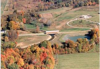
Figure 222. Existing site with poor alignment.
The first phase of construction was to build new abutments. They are standard stub abutments that bear directly on bedrock. The total height of abutments was 5.2 m (17 ft). Rock channel material would later be placed to provide erosion and scour protection. To correct both stream and highway alignment problems, the decision was made to relocate the new bridge. After the new bridge was built, the stream was relocated to flow under the new bridge.
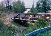
Figure 223. New abutment construction on new alignment.
Figure 224. New stub abutment stem.
The main trusses were built with Southern Pine glue-laminated lower chords and floor beams. To minimize the number of tension splices in the lower chords, 19.5-m- (64-ft) long timbers were used. Splices consisted of steel plates with bolts and 100-mm- (4-inch) diameter shear plates. The upper chords and verticals were built with solid-sawn Southern Pine. The upper chords were triple metric needed 150x400x7.3m (6"x16"x24') long. Also in the plane of the trusses are metric needed 75x250x2.4m (3"x10"x 8') oak timber diagonals that act as spacers between the elements.
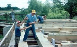
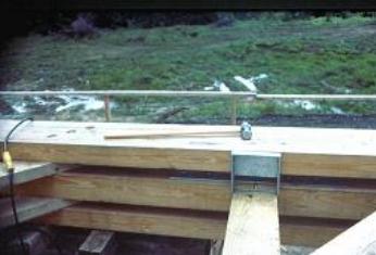
Figure 226. Three chord elements.
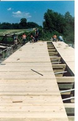
Figure 227. Adding siding before truss lifting and installation.
All chords and verticals are triple element members with approximately 75 mm (3 inches) between the elements. Twin steel diagonal tension bars pass through the gaps. The diagonal bars range in size from 50-63 mm (2-2.5 inches) diameter. Bearing plates are provided to transmit the load to the chords. Grooves are provided in the chords to resist lateral movement of the plates. The ends of the tension bars are threaded for the tightening nuts.
The floor beams (two per panel) are 220x420x6.7m (8¾"x 16½"x 22') spaced 1.2 m (4 ft) apart. They are hung from the lower chords using two 22mm (7/8'") diameter bolts at each end. 150 mm by 230 mm (6"x 8") white oak timbers are attached on the floor beams and run longitudinally at a 405-mm (16-inch) spacing. The next layer consists of 75-mm- (3-inch) thick transverse white oak planking. 2" thick oak runners were used to smooth out the ride in the bridge.
The roof system consists of 7/12 pitch trusses with a 100 mm x 200 mm (4"x 8") upper chords and twin 100 mm x 150 mm (4"x 6") lower chords. The roof truss spacing is 1.2 m (4 ft). Purlins are 75 mm x 100 mm (3"x 4") members spaced at 200 mm (8 inches). Wood shingles were nailed to the purlins.
Sway bracing consists of 100 mm x 250 mm x 3.0 m (4"x10"x10') oak knee braces at 2.4-m (8-ft) spacing. Upper lateral bracing consists of 200 mm x 200 mm (8"x 8") transverse with diagonal cross bars.
For longevity, the main trusses and floor beams were treated to prevent deterioration. All steel hardware was hot-dip galvanized.
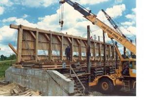
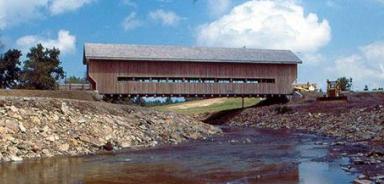
Figure 228. North truss in position and secured.
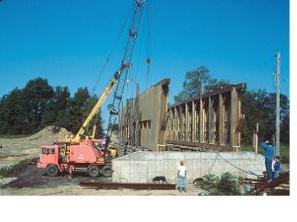
Figure 229. Both trusses erected.
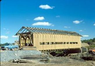
Figure 230. Installation of roof trusses and purlins.
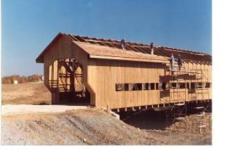
Figure 231. Installation of wood shingles.
All photos courtesy of John Smolen

