U.S. Department of Transportation
Federal Highway Administration
1200 New Jersey Avenue, SE
Washington, DC 20590
202-366-4000
Federal Highway Administration Research and Technology
Coordinating, Developing, and Delivering Highway Transportation Innovations
 |
| This report is an archived publication and may contain dated technical, contact, and link information |
|
Federal Highway Administration > Publications > Research > Structures > Covered Bridge Manual |
Publication Number: FHWA-HRT-04-098 |
Previous | Table of Contents | Next
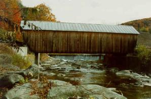
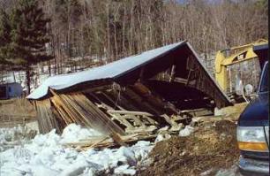
Figure 234. Destroyed March 4, 1999.

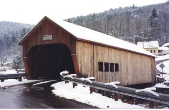
Figure 235. View in December, 2002.
A covered bridge was constructed over the first branch of the White River in the heart of the Village of Tunbridge, VT, in 1883. The single-lane structure was supported by multiple kingpost trusses and was approximately 22 m (72 ft) long (see figure 236). Unfortunately, the bridge was struck by ice on March 4, 1999, and collapsed the following day.
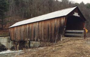
Figure 236. A view of the original bridge
The community wanted to replace the bridge with another covered bridge, and the Vermont Agency of Transportation supported the project by providing the bulk of the funding for the new bridge.
The design criteria for the project included a stipulation for a design vehicle of a single 13.5-MT (15-ton) truck (a convenient bypass exists for heavier vehicles). Further, the trusses were to be built of local native Hemlock, if possible, with similar sizes and configuration as the original bridge. Unfortunately, the design stresses resulting from using the original member sizes would have required select structural Hemlock. Although some local timber sawyers were confident that they could provide acceptable good quality timber, a lumber grader willing to certify that grade could not be found. Accordingly, it was concluded that local Hemlock in the grading necessary was not available. Select structural Douglas Fir was accepted as an appropriate substitute for the critical truss elements.
One unusual detail in the design involved reinforcing the corbels of the vertical posts against shear failure. The details involved inserting four 25.4-mm (1-inch) diameter hardwood pegs in the corbel to provide additional resistance to high shear stresses (see figure 237). According to the analysis of the bridge, the reinforcement was required in only the end three-post elements. Unfortunately, shortly after the bridge was opened to traffic, an overweight vehicle crossed the bridge, contrary to the posted weight restriction, and caused a shear failure in an unreinforced corbel. A steel rod was inserted adjacent to the post as a repair (see figure 238).Figure 239 shows a closeup of the rod connection, and the arrows indicate a slight vertical dislocation along the slip plane. This indicates that it would be wise to reinforce more corbels than required by the design vehicle; the cost was nominal at the time of construction, and the repair was difficult to install with the siding in place and with the bridge located over water.
Figure 237. Wooden peg reinforcement of post corbel.
(photo courtesy of Scott Sabol)
Figure 238. Reinforcement rod.
(photo courtesy of Scott Sabol)
Figure 239. Closeup of the failed corbel after the repair.
The bottom chord tensile splices duplicated the use of bar and rod connections, one of several types of tensile connections commonly used in original covered bridge construction (refer to figure 240). This is a view of the original. The replica bridge used a very similar detail.
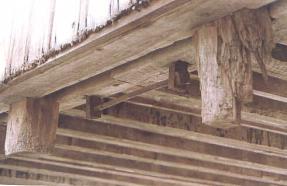
Figure 240. Bar-and-rod connector tensile splice.
Another important issue related to the bracing of the original bridge. Although the bridge had managed to survive for more than 100 years, the internal bracing was minimal. The contractor sought approval for installation of heavier internal bracing, and permission was granted. New stout tie beams were installed along with heavy knee braces that were connected above the tie beams to form a substantial transverse frame.
Timber curbs were installed at 3-m (10-ft) spacing along the bridge to prevent vehicles from impacting the knee braces, a common occurrence at the previous bridge (see figure 241). The gap between curb and approach rail allows pedestrian traffic to pass through the bridge outside of the curb. Note the reflector used at the end of the curb-an effective identifier.
(photo courtesy of Scott Sabol)
Figure 241. Transition from approach rail to inside curb.
The bridge was built on the approach roadway and moved into place with steel rollers supported on two steel I-beams spanning between the abutments. Consistent with the traditions of original construction practices, the power for the relocation of the bridge was provided by oxen turning a capstan (see figures 242 and 243). Figure 244 provides a view of the completed bridge. Note that the windows exist specifically to facilitate traffic crossing through the bridge from the far side to help users see the sharp roadway curve on this side.
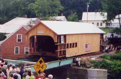
Figure 242. Bridge being moved into position.
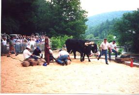
Figure 243. Oxen power and capstan.
(photo courtesy of Scott Sabol)

