U.S. Department of Transportation
Federal Highway Administration
1200 New Jersey Avenue, SE
Washington, DC 20590
202-366-4000
Federal Highway Administration Research and Technology
Coordinating, Developing, and Delivering Highway Transportation Innovations
 |
| This report is an archived publication and may contain dated technical, contact, and link information |
|
Federal Highway Administration > Publications > Research > Structures > Covered Bridge Manual |
Publication Number: FHWA-HRT-04-098 |
Previous | Table of Contents | Next
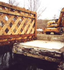
Figure 245. New pad at East Abutment-truss erection underway.
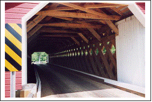
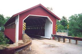
Figure 246. Entrance of completed bridge.
The Paper Mill Covered Bridge was built over the Walloomsac River a few miles north of Bennington, VT, in 1889. The 38.1-m- (125-ft) long Town lattice truss supported bridge was built with unusually shallow trusses, compared to the many other Town lattice truss bridges in the area. It is unknown if the bridge had repairs earlier, but extensive reconstruction of the bridge was undertaken in 1952. Again suffering from distress, the bridge was bypassed in the 1980s but continued to serve pedestrian traffic. Finally, in the mid-1990s, continuing deterioration required installation of substantial interior bracing to stabilize the bridge until major rehabilitation could be undertaken. Figure 247 depicts a view of the bridge before the recent work. Note the substantial horizontal wave of the top chord, indicating serious distress.
Figure 247. The bridge before work.
The initial study had identified major rot of the top chord on the upstream truss, as a result of long-term leakage through a hole in the roof. (The roof of the bridge was used by local residents as a diving platform into the adjacent swimming hole of the millpond; the hole provided access to the roof from inside the bridge.)
The repair work in the 1950s included disassembling the trusses and replacing many members. Unfortunately, the reassembly of the bottom chord included inserting split ring connectors in the middle of the trunnel patterns. The resulting section loss of the main elements reduced their capacity to such an extent that they were unable to safely support even the self-weight of the bridge, much less any snow or pedestrian/vehicle loading.
The work on the bridge was intended to restore its capacity for support of vehicular loading so that the temporary bypass structure could be removed. The design criteria for the project, as provided by the Vermont Agency of Transportation, included a single 18MT (20-ton) truck.
As a consequence of the well-intentioned, albeit damaging, previous installation of split ring connectors in the bottom chord/lattice intersections, salvaging the otherwise undamaged lattice elements was impractical. All of the bottom chord elements were theoretically unable to support their loads, even if in good condition. The top chords had been so overloaded that they were badly distorted and bowed, making their retention impossible. Accordingly, following significant debate and consultation among various involved parties, the decision was made to completely replace the trusses. A few of the original lattice elements were retained at the ends of the trusses where they are terminated above the bottom chord, and are thereby not affected by the section removal from the split ring connectors.
The bridge owner wanted to retain the original geometry of the trusses. While this produced a replica bridge that, to the lay observer, resembles the original, it nonetheless introduced a structural weakness, in that the depth of the bridge would benefit from an increase to lessen the loads in the chords.
The structural analysis of this replica included a very sophisticated finite-element analysis. In addition to the basic force analysis of the lattice and chord elements, it also included a review of the shear stresses in every shear plane of every trunnel group at each chord/lattice or lattice/lattice intersection. The use of solid-sawn timbers required 4x14 select structural Southern Pine bottom chord elements to replace the original 3x12 members. Four 51-mm (2-inch) diameter oak pegs were used for the bottom chord connections at each lattice intersection.
The shallow depth of the trusses caused higher chord forces, thereby requiring substantial overhead bracing. The traditional timber knee braces between the sides of the lattice elements to the underside of the tie beams were augmented with longer elements beside and above the knees (see figure 248) to strengthen the overhead system. The older, shorter elements were bolted to the side of the longer extensions. The extensions above the tie beams were joined at the peak.
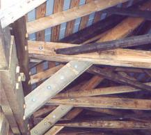
Figure 248. Modified knee braces.
The lattice trusses were built flat, as is typical. When they were complete, the trusses were moved into position using cranes and a flatbed truck that was able to traverse the adjacent bypass bridge before it was removed (refer to figure 249).
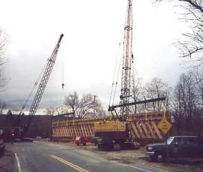
Figure 249. Cranes and truck positioning the trusses.
The floor system is comprised of glue-laminated floor beams (nominal 250 mm by 380 mm) (10 inches by 15 inches) at 1.2-m (4-ft) spacing with 150-mm (6-inch) nominal thickness glue-laminated panels. New concrete-bearing seat caps were cast on top of the existing dry-laid stone abutments.
Work began in November, 1999, and construction was completed and the bridge reopened to traffic on July 13, 2000 (see figure 250).