U.S. Department of Transportation
Federal Highway Administration
1200 New Jersey Avenue, SE
Washington, DC 20590
202-366-4000
Federal Highway Administration Research and Technology
Coordinating, Developing, and Delivering Highway Transportation Innovations
 |
| This report is an archived publication and may contain dated technical, contact, and link information |
|
Publication Number: FHWA-HRT-06-078
Date: June 2006 |
|||||||||||||||||||||||||||||||||||||||||||||||||||||||||||||||||||||
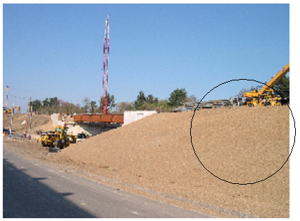
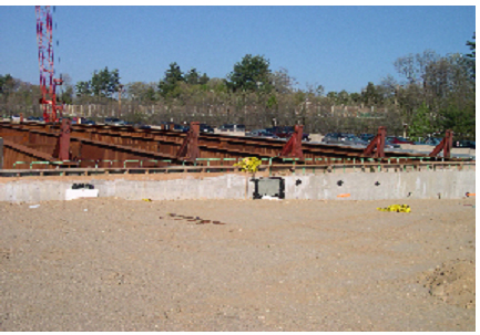
Job Site Evaluation of Corrosion Resistant AlloysAPPENDIX F FHWA Project NUMBER NH-02-03TEA-21 INNOVATIVE BRIDGE CONSTRUCTION PROGRAM Evaluation Report October 27, 2004 State: New Hampshire. State DOT Contact: Mr. Paul Nadeau [(603) 645-1760]. NBI Bridge Number: 016101850007700. Project Type: Replacement. Location: Bridges on I-293 over Frontage Rd. and Brown Ave., Manchester, NH. Innovative Material: Galvanizing reinforcing steel. Bridge Description: These two bridges are discussed in a single report because of construction and innovative reinforcement commonalities and their proximity to one another. In each case, there are two-lane east- and westbound bridges that are part of a number of bridge reconstructions and replacements along I-293. The Frontage Road Bridge is about 300 mi east of the Brown Avenue Bridge. Figure 44 shows a perspective view of the latter bridge where the girders are set but the deck formwork has not been placed. Note job site storage of the galvanized reinforcement (circled) to the right of the in-place girders. Figure 45 provides a closer view. The deck specifications call for longitudinal #5 bars with 8-inch spacing and transverse #6 at 6-inch spacing. While a pavement overlay is normally employed for New Hampshire bridges, this is not being called for on the Frontage Road or Brown Avenue Bridges.
Figure 44. General view of the Brown Avenue Bridge under construction.
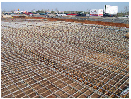
Classification of galvanized reinforcement as innovative is conjecture, since this material has been available for decades, although its use as reinforcement in bridge construction has been limited. The fact that results from both research and field experience have been mixed from the corrosion performance standpoint, however, warrants its being included in this program. Construction Sequence: At the time of the site visit (May 6, 2004), only the girders were in place on the Brown Avenue Bridge as noted above in conjunction with figures 44 and 45. Construction was more advanced at Frontage Road as explained below. Figure 46 shows a general view of the galvanized bar placement on the Frontage Road deck.
Figure 46. In-place galvanized reinforcement on the Frontage Road Bridge deck. Reinforcement Specification: Initially, Type 316L or 316LN reinforcement conforming to AASHTO M 31M (M31) in accordance with ASTM A-955M-96 was specified for both Brown Avenue Bridges and 316L clad black bars (AASHTO M 31M (M31)) for the Frontage Road ones. The two east bound bridges were replaced in 2003; but because suppliers were unable to provide the stainless steel, ECR was substituted. This same supply problem arose for the clad reinforcement in 2004, and galvanized reinforcement was used as a substitute here. Material Cost: Table 11 lists the as-bid costs for both the originally specified stainless and stainless clad reinforcement and for the replacement galvanized reinforcement for both bridges.
Concrete Specification: The concrete mix design is shown in table 12. This requires a minimum 30 MPa (4,000 psi) compressive strength at 28 days.
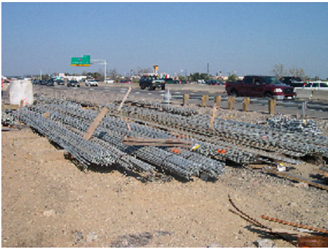
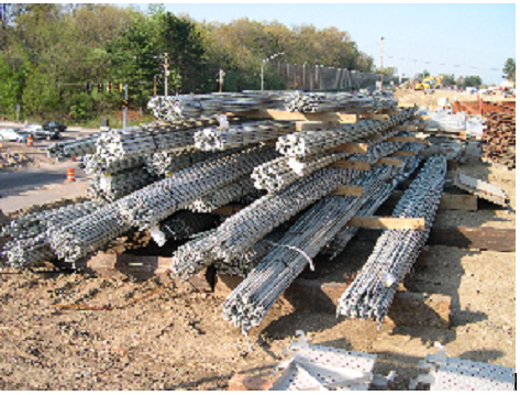
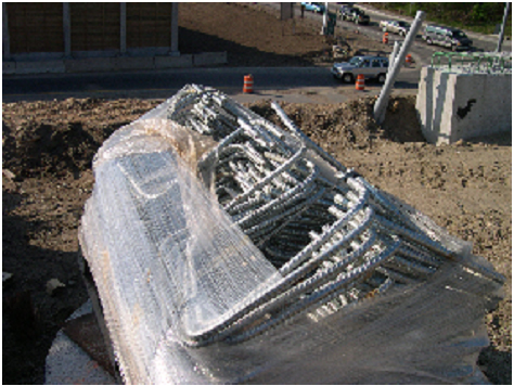
Prime Job Contractor: George R. Cairns & Sons Subcontractor: E.D. Swett, Inc. 8 Industrial Park Dr. Concord, NH 03301 (603) 224-7401 Steel Supplier: Barker Steel Company, Inc. 55 Sumner Street Milford, MA 01757 Job Site Storage: The galvanized steel for both bridges was delivered in plastic wrapping just prior to the placement schedule for the Frontage Road Bridge. Figures 47 and 48 show views of bar storage at this latter site. A distant view of bars at the Brown Avenue Bridge was indicated in figure 44, and figures 49 and 50 show closer views of straight and fabricated bars, respectively, at this location.
Figure 47. Bundled/wrapped bars at the Frontage Road job site.
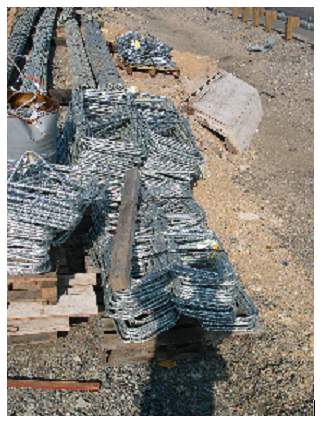
Figure 48. Fabricated galvanized bars at the Frontage Road Bridge job site.
Figure 49. Stored galvanized bars at the Brown Avenue Bridge job site.
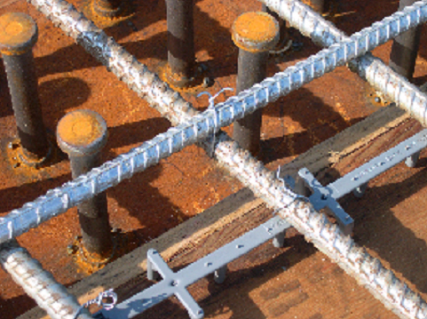
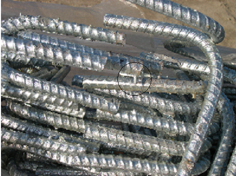
Presence of Carbon Steel: Shear studs on the top girder flanges are carbon steel. A distant view of these can be seen in figure 46, and figure 51 provides a closer view. While no instances of electrical contact between the two metal types were apparent, this could inadvertently occur. Because potential of galvanized steel can be active to passive black steel, a corrosion cell could be established.
Figure 51. Closeup view of the in-place galvanized reinforcement relative to carbon steel studs. Innovation Justification: Northern bridge decks in New Hampshire endure heavy winter precipitation and deicing salt use. Innovative reinforcements that provide enhanced corrosion resistance relative to that of black steel are being increasingly recognized as competitive on a life-cycle cost analysis basis. Problems: The following difficulties and potential difficulties were cited for these two bridge projects:
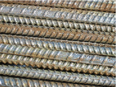
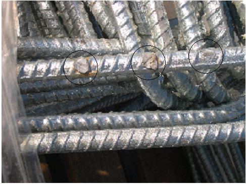
Figure 52. Deposits on galvanized reinforcing bars.
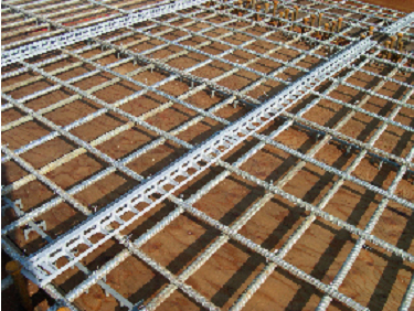
Figure 53. In-place bottom galvanized rebar mat with plastic mat spacer.
Material Acquisition: The project team was able to acquire samples of the galvanized bars from the job site for analysis.
|
|||||||||||||||||||||||||||||||||||||||||||||||||||||||||||||||||||||