U.S. Department of Transportation
Federal Highway Administration
1200 New Jersey Avenue, SE
Washington, DC 20590
202-366-4000
Federal Highway Administration Research and Technology
Coordinating, Developing, and Delivering Highway Transportation Innovations
 |
| This report is an archived publication and may contain dated technical, contact, and link information |
|
Publication Number: FHWA-HRT-06-078
Date: June 2006 |
|||||||||||||||||||||
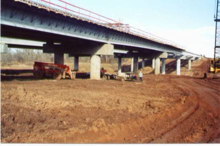
Job Site Evaluation of Corrosion Resistant AlloysAPPENDIX G FHWA Project Number OK-01-01TEA-21 INNOVATIVE BRIDGE CONSTRUCTION PROGRAM Evaluation Report8 State: Oklahoma. State DOT Contact: Mr. John Leonard [(580) 336-7374] Mr. James Gilbreath [(580) 336-7374]. NBI Bridge Number: 26415. Project Type: Replacement Bridge. Location: Bridge crossing Chickaskia River on I-35 in Kay County, OK. Innovative Material: MMFX-II Reinforcing Steel. Bridge Description: The new bridge comprises the two northbound lanes at the above location. The southbound bridge of the same design was completed one year earlier and employed epoxy-coated reinforcing steel. Overall length of the bridge is 200 m (657 ft) and total width 12.3 m (40.4 ft) and consists of five spans on four piers with 1.80 m (5.90 ft) diameter drilled shafts with cast-in-place caps and bulb-tee prestressed concrete beams. Deck design was by the empirical method. Initially, stainless steel clad reinforcement was specified; but because of delivery problems, this was changed to MMFX-II. Figure 56 shows a general view of the bridge at the time when the deck was being formed.
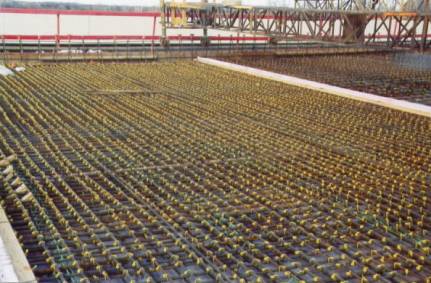
Figure 56. General view of the I-35 northbound bridge. Innovation Justification: The anticipated good corrosion resistance of MMFX-II reinforcing steel is anticipated to result in reduced maintenance and life-cycle cost for the bridge. Construction Sequence: The deck was placed from south to north with each span being formed and poured as a separate unit. Figure 57 shows a perspective view of the as-formed deck reinforcing steel as seen from east to west across span 1. Figure 58 provides a closer view, including an ECR spacer that separates the two mats and reinforcing steel from a girder. Figure 59 shows the tie-in of the parapet wall reinforcing steel to the deck. Slab thickness is 8 inches and the reinforcement is comprised of #4 and #5 bars. Cover over the top steel is 2.4 inches.
Figure 57. In-place deck reinforcing steel.
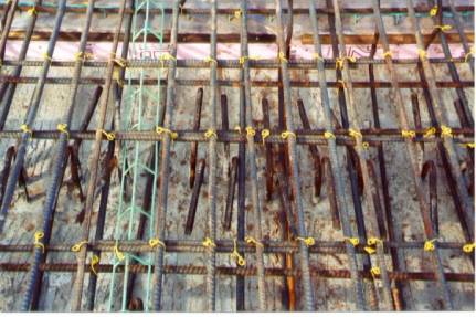
Figure 58. Closeup view of MMFX-II deck reinforcing steel.
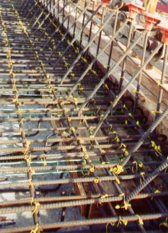
Figure 59. Reinforcing steel as placed in the deck and parapet wall. Reinforcement Specification: At the time of construction, no national standard existed for MMFX-II reinforcing steel. In lieu of this, the manufacturer’s “Product Bulletin” dated September 2001 was employed. Concrete Specification: The concrete was termed, “Special Deck,” with mix design as specified in table 13. Because MMFX-II was anticipated to be less corrosion-resistant than the clad stainless steel, the admixture IPANEX®, which has corrosion inhibiting attributes, was added via a change order.
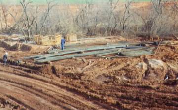
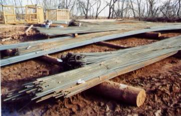
Job Contractor: Muskogee Bridge Co., Inc. P.O. Drawer 798 Muskogee, OK 74402 (918) 683-3051 Steel Supplier: MMFX Steel Corporation of America, Inc. The steel was produced by Birmingham Steel, 3630 Fourth Street, Flowood, MS 39208. Material Cost: A total of 167,790 pounds of MMFX-II reinforcing steel was ordered for the project. The unit material cost was $0.88/lb for a total cost of $146,863. Job Site Storage: The steel was delivered via truck and stored uncovered outdoors on timbers. A crane was employed to move the steel to the deck, where it was placed by hand. Figure 60 shows a perspective view of the storage location, and figure 61 provides a closeup view.
Figure 60. Perspective view of steel storage site.
Figure 61. Closeup view of stored bars on timbers at job site. Problems: Difficulties that were encountered with the companion, southbound bridge, which do not relate to the reinforcement but rather to structural problems, led to doing away with the elastomeric pads at piers 1 and 4 and installing expansion joints at these locations. Closure pours were not made here; and instead, these areas were poured with the adjoining slabs. The longitudinal steel was shortened to allow for expansion devices. There was a 5-week period between the time the order for MMFX-II was placed and the steel was delivered. Because the change from clad stainless steel to MMFX-II reinforcement was anticipated ahead of time, no project delay resulted. Material Acquisition: Several lengths of reinforcing steel were made available from the job site for testing by FAU and FDOT 8 The description for this bridge utilizes English and not metric units since the project documents and specifications were so based.
|
|||||||||||||||||||||